Transcription
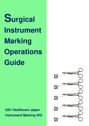
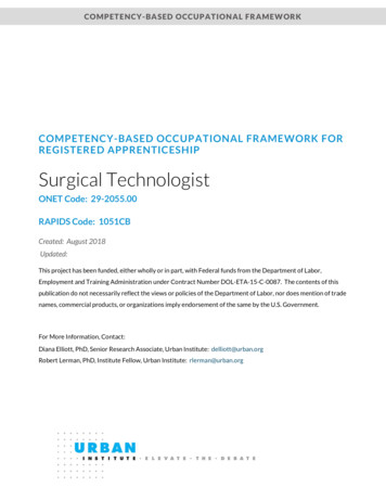
An Interchangeable Surgical Instrument Systemwith Application to Supervised Automation of Multilateral TumorResection.Stephen McKinley1 , Animesh Garg2 , Siddarth Sen3 , David V. Gealy1 ,Jonathan P. McKinley1 , Yiming Jen3 , Menglong Guo1 , Doug Boyd4 , Ken Goldberg2Abstract— Many surgical procedures require a sequence ofdifferent end-effectors but switching tools for robot-assistedminimally-invasive surgery (RMIS) requires time-consuming removal and replacement through the trocar port. We present aninterchangeable instrument system that can be contained withinthe body cavity. It is based on a novel mounting mechanismcompatible with a standard RMIS gripper and a tool-guideand sleeve to facilitate automated instrument switching. Experiments suggest that an Intuitive Surgical system using theseinterchangeable instruments can perform a multi-step tumorresection procedure that uses a novel haptic probe to localize thetumor, standard scalpel to expose the tumor, standard grippersto extract the subcutaneous tumor, and a novel fluid injectiontool to seal the wound. Design details and video are availableat: .I. I NTRODUCTIONRobotic Surgical Assistants (RSAs) are frequently usedwith high success rates for Robotic Minimally InvasiveSurgical (RMIS) procedures such as prostatectomy, ureterectomy, tumorectomy, and nephrectomy within the abdominaland thoracic cavities [7, 27]. Intuitive Surgical’s da VinciRobotic Surgical Assistant (RSA) facilitated over 570, 000procedures in 2014 with 3000 RSA systems worldwide [13].RSAs are currently controlled by surgeons via pure teleoperation, requiring constant surgeon attention and control.Supervised autonomy of surgical sub-tasks has the potentialto reduce surgeon tedium, fatigue, and operation time.Interchangeable surgical end-effectors allow for smallerincision wounds [29] and decreased surgical time [23], butcurrently available modular tools do not have a wristeddegree of freedom thus decreasing surgeon efficacy. Toaddress the problem of modularity and interchangeability, wehave developed several novel devices, including interchangeable low-cost instrument mounts for retractors with wristedarticulation as illustrated in Figures 1 and 3, to be used toexplore automated tumor resection.We consider the multilateral surgical procedure of tumorresection which includes four sub-tasks: (a) Palpation, (b)Incision, (c) Debridement, and (d) Adhesive Injection. Thesesub-tasks represent a selection of those included in theUniversity of California, Berkeley, CA, USA1 Mechanical Engineering{mckinley, dgealy, jmck11,m.guo}@berkeley.edu2 IEOR & EECS, {animesh.garg, goldberg}@berkeley.edu3 EECS, {siddarthsen, yjen}@berkeley.eduUniversity of California, Davis, CA, USA4 UC Davis Medical Center, wdboyd@ucdavis.eduFig. 1: Surgical tumor resection overview with interchangeablemounts for da Vinci surgical retractor and three end-effector extensions.Fundamental Skills of Robotic Surgery (FSRS) [32] usedfor training laparoscopic surgeons [8, 31]. We explore theautomation of this procedure using the da Vinci SurgicalResearch Kit (dVRK), a commercial RMIS system fromIntuitive Surgical [16] with silicone-based simulated tissuephantom. Tumor resection requires multiple instruments: ahaptic device for palpation, a blade for incision, grippers fordebridement, and a syringe pump for injection. Changinginstruments during surgery is time consuming and currentlyrequires a pause in the surgical procedure for human intervention. We consider a scenario where the standard surgicalgrippers can interface with multiple tool-tips to increase theautomation during robotic laparoscopy.Contributions1. Designs of novel interchangeable instrument mount compatible with standard RMIS gripper.2. Design of a novel tool-guide and sleeve to facilitateautomated switching between instruments.3. Application of the interchangeable instrument system tomulti-step supervised autonomous surgical tumor resection involving changes between haptic probe, scalpel,fluid injector, and standard grippers.II. R ELATED W ORKA. Interchangeable MIS Instrument SystemsThere have been a number of studies on nonrobotic laparoscopic instruments with interchangeable endeffectors [18, 30]. However, the end-effectors of these in-
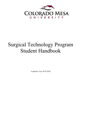
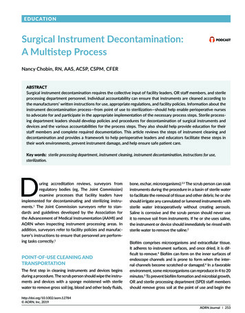
Fig. 2: A schematic view of a da Vinci Classic instrument insertedthrough a trocar port into the abdominal cavity.TABLE I: Comparison of Wrist, Clevis, and Jaw Mounting.struments allow only a single degree-of-freedom (jaw opening/closing) and do not interface with existing surgical retractors. Most existing robotic systems such as the da Vinciand DLR MICA exchange the entire instrument instead ofthe end effector [1, 37].Implementation of Interchangeable Systems: Currently,the instrument change procedure for the da Vinci RSAinvolves the complete removal of the instrument from withinthe abdominal cavity through the trocar port (see Figure 2).To make interchangeable instrument end-effectors beneficialto RMIS, end-effectors can be introduced through a separateutility trocar port as described in [33]. The utility trocarport can also be the point of entry for electronic cables andcatheters as described in [18] allowing for sensorized andfluid delivery end-effectors to be introduced into the RMISworkspace.Robotic Interchangeable Instrument Systems: In 2007,Friedman et al. proposed the early use of a robotic systemto automate instrument change on the da Vinci RSA [10].However, their method required additional automated infrastructure including an industrial arm used to change the entireda Vinci instrument after removing it from the abdominalcavity.Commercially Available Devices: In 2015, Teleflex Medical was granted FDA clearance to market interchangeableinstrument-tips for non-robotic MIS instruments with a singledegree of freedom [36].Existing non-robotic interchangeable instrument endeffectors are not compatible with existing retractor geometry,limiting the combination of possible instrument configurations. Additionally, all of these devices allow only a singlecontrollable degree-of-freedom at the instrument tip withsimilar limitations as in our initial design for a wrist mount(described in Figure 3(b) and shown in Figure 3(c)).B. Autonomous Multilateral Surgical Tumor ResectionThis paper focuses on the demonstration of tumor resection as imagined in a silicone-phantom tumorectomywhich includes four sub-tasks [9]: Palpation, Incision, Debridement, and Injection, using the finite element approachdescribed in a previous work [25]. Several researchers haveexplored autonomous performance of RMIS sub-tasks [2, 6,35, 39]. Moustris et al. [24] and Kranzfelder et al. [20] provide reviews of recent developments in semi-autonomous andautonomous execution of various experimental and clinicalsurgical procedures.Palpation is necessary for surgeons to find inclusionswithin tissues. Konstantinova et al. [19] provide an extensivesurvey on recent advances for sensor design and deployment to enable successful haptic palpation. Algorithms foractive exploration in tumor localization [26] and tumor ablation [12] offer new methods to consider for improved roboticpalpation outcomes. Sterilization of instruments remains achallenging limitation for clinical use of tactile force sensingin RMIS [4]. In this work, we automate the palpation probedesign presented by the authors in 2015 [22].Scalpel instruments are available as stand-alone tools forthe da Vinci. However, they do not allow for interchangeability of instrument-tips. We created a scalpel instrumenttip (shown in Figure 1(b)) compatible with the proposedinstrument mount for use in the automated tumor resectionpipeline as described in Section V. In surgical theaters, electrical cauterization is generally used for resection. However,these instruments won’t function properly in a silicone-basedphantom tissue.Surgical debridement is a tedious surgical sub-task inwhich foreign inclusions or damaged tissues are removedfrom the body [5, 11]. Automated brain tumor ablation andresection with the RAVEN II has been explored in simulation [12]. Kehoe et al. [17] used motion planning to performmultilateral surgical debridement using the Raven II surgicalrobot. We have explored tissue debridement and multilateralcutting on deformable materials with the dVRK [25].Targeted fluid injection allows for controlled and precisedelivery of materials such as chemotherapy drugs, surgicalglues, and stem cells. However, delivery to organs in inaccessible locations such as in the thorax, abdomen and pelvis ischallenging because of the relatively high degree of traumarequired [15]. Non-MIS robot injection tools have beendeveloped and evaluated in the past [34]. Robotic catheterinjection tools have also been studied [3]. However, thereis a need for low-cost RMIS compatible delivery deviceswhich enable access to internal organs and deliver controlledquantities of localized fluids [14].There are a number of clinically used methods for woundclosure including suturing, staples [38] and surgical adhesives. Padoy et al. [28] demonstrated execution of a humanrobot collaborative suturing task on the daVinci platformwith a research interface. Surgical glue has shown promise inclosing small scale inter-cavity hernias [21], but little workexists on the use of RSAs for precision application of fluids.III. S YSTEM D ESIGN AND I NTERFACINGOur design motivation is to develop modular tooling forthe dVRK to allow for the demonstrable automation of amulti-step surgical procedure. The interchangeable mountingsystem has:
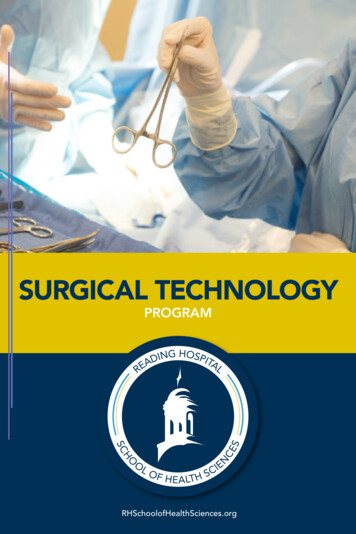
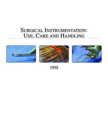
Fig. 3: Three designs for end-effector instrument mounts differentiated by attachment strategies to the surgical retractor. We found that theusable workspace of the Palpation Probe decreases as degrees of freedom (a) are restricted. The surgical retractor in (c) extends axiallywithin the mount. The retractor in (d) is inserted at level with the clevis pulley seen in (a).1. Kinematically constrained mounting on a standard surgical retractor end-effector using existing geometric features2. Self-actuating retractor fixation requiring minimal gripforce3. Preservation of existing retractor articulation4. Form factor to fit through a 15 mm cannula during minimally invasive procedures5. Low-cost for single-use disposability.A. Clevis Mount DesignWe introduced a low-cost wrist-mounting design in ourrecent work for use as a minimally invasive palpation sensor [22] shown in Figure 3(c). However, due to the sleeveenclosure, the motion of the end-effector is restricted to onlywrist rotation as shown in Table I. This limits the range ofmotion of the surgical retractor as illustrated in Figure 3(b).We designed an interchangeable instrument-tip mount toaddress these limitations by mounting on the ‘clevis’ linkof the surgical retractors (see Figure 3(a)) providing stabilization (as shown in Figure 3(d)). The cavity on the clevismount (illustrated in Figure 5) was designed to help funnelthe dVRK needle driver into its proper orientation, allowinga higher tolerance for misalignment in settings without visualfeedback and easing the demands on software. The furthestproximal extent of the mount extends up to the clevis jointlinkage; any further extension along this axis would limitclevis rotation as shown in Figure 3(b). The cavity of themount mates with the side contour of the surgical retractorto limit rotation away from the ‘z’ axis (defined in Figure 5)yet maintains a sliding fit to allow the retractor to detacheasily.The internal cavity of the clevis mount is designed withlocking pins extending from the walls of the interchangeablemount. The pins securely engage shoulders located on theretractor jaw when open (’Contact Points’ marked on Figure 5). The angle of these pins (angle ‘γ’ shown in Figure 5)matches the angle of the shoulders on the opened jaws tomaximize contact area. A self-actuating lock is achievedas the points of contact on the jaw are angles such that adisturbance forces the jaws further open in contact with theinternal cavity of the mount as a force in the positive ‘z’direction is applied (shown in Figure 5). Movement in thenegative ‘z’ direction is limited by contact between the clevislinkage and the internal cavity of the interchangeable mount.The clevis mount allows greater range of motion along the‘x-y’ plane as shown in Figure 3(b); however, because jawrotational motion was restricted, the workspace is limited toa narrow ellipse along the ‘x’ axis as shown in Figure 3(b).Despite these limitations, we were able to demonstratethe utility of a self-engaging interchangeable instrument-tipmount by performing tumor resection surgeries in siliconflesh phantoms as described in Sections VI and V.B. Jaw Mount DesignThe jaw mount design was created to extend the utility ofthe clevis mount design by allowing greater range of motionin jaw rotation axes. Mount movement in the negative ‘z’direction is constrained by an internal spur that mates withthe ‘palm’ of the surgical retractor clevis between the tworetractor jaws. The mating cavity was created by laminating
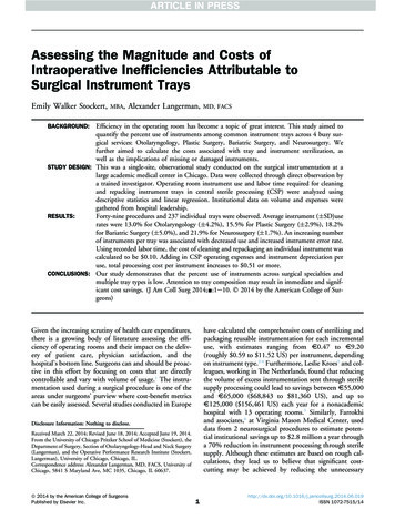
Fig. 4: A self-actuating mount: Force disturbance F in the negativez direction is countered by the contact points between the mountpins and the retractor shoulder. This results in an outwards clampingforce F’ to the clevis mount. The interchangeable mount can bedesigned with any external shape.Fig. 5: The Jaw-Tip mount allows a smaller form factor and can be3D printed as a single piece shown in purple (requiring no additionalmanufacturing steps). This component can be added to surgicalperipherals to interface the Robotic Surgical Assistant to a widevariety of user-defined devices.water-jetted 1095 spring steel sheets of 0.025 in thicknessusing two M2 machine screws. Points to engage the retractorshoulders were designed integrally to the laminate layers.This interchangeable mount is affixed to modular instrumenttips and end-effectors as shown in Figures 3(e) and 5.IV. D ESIGN FOR AUTONOMOUS T OOL -C HANGINGAbove we describe methods for interfacing tools anddevices temporarily to the tips of surgical retractors. Anextension of this concept would be to develop an interchangeable tool attachment for the 3-D printed jaw-tip mountthat enables changing tools autonomously. We developeda novel Tool-Changing Adapter (TCA) that mounts on an8mm Needle Driver as shown in Figure 6. The tool changercan be used with a two- or three-arm surgical robot. Toolscan be loaded onto the tool-changer and inserted into thebody cavity through the cannula to be affixed to the surgicalarm(s) already within he body. The tool changing attachmentconsists of an indexing channel and a finger-tip mountthat interfaces to the 8 mm Needle Driver as discussed insection III-B.Aspects of the TCA design that were motivated by autonomous robotic interaction are highlighted in Figure 6; inthis figure, the orange arm is removing the palpation probefor use elsewhere in surgery and is the retrieving tool. Themodular jaw-tip tool mount described in Section III-B can beused for the point of attachment for the TCA, and remainsthe starting point for additional modular tools. The RetainingCatch holds the jaw-tip mount in place during repeated toolexchanges; this is a passive fixation. The Tool Return Guidesforce the returning jaw-tip mount to mate with the base of thecatch basin, indexing the jaw-tip mount for the next removal.The Shaft Catch Basin provides a large landing area for theretrieving surgical arm to mate with the TCA rather thanattempting to visually servo the points of the gripper jawsinto the jaw-tip mount. The Gripper Ramp passively forcesthe retrieving arm to rotate its shaft such that the tips ofthe gripper jaws insert properly within the retrieved tool.The Indexing Slot guides larger tools (such as the PalpationProbe shown in Figure 6) into place within the catch basin.Autonomous Tool-Changing Evaluation: A static thirdarm was added to the DVRK as shown in blue in Figure 6 andis know as the presenting arm. The position of the presentingarm was calibrated to the global coordinate frame of theDVRK by tele-operating the individual arms to the locationof the indexing channel on the tool-changing interface. Oncethe location of the static presenting arm is known the toolchange process is repeatable. In experiments, we were ableto demonstrate robustness by exceeding 30 repeated toolchange operations with the same hardware being re-used.However, this trial was performed ’open-loop’: once theposition of the presenting arm deviates from the initial setup,all repeatability is lost. Further development of the TCA willinclude features that are designed to facilitate visual servoingof the retrieving arm into the Shaft Catch Basin.V. E XPERIMENTSTumor resection includes four sub tasks: Palpation, Incision, Debridement, and Injection. Palpation of tissues is ameans by which surgeons verify the location of tumors tomake precise incisions using their sense of touch. Retractionand debridement require the interaction of the dVRK withflexible tissues. Surgical adhesive applications require theplacement of discrete amounts of fluid to precise locations.Experimental Setup: The palpation probe was affixedto the 8mm Needle Driver by manually placing the clevismounted probe below the surgical retractor, then promptingthe jaws to open. The location of the flesh phantom wasregistered to the dVRK robot by manually tele-operating tothe corners of the phantom and recording the global robotpose when palpation probe end effector distance was nonzero. These recorded points were used to fit a plane to thesurface of the tissue.For wound closure, we designed an automated injectioninstrument with three components: end-effector mounted
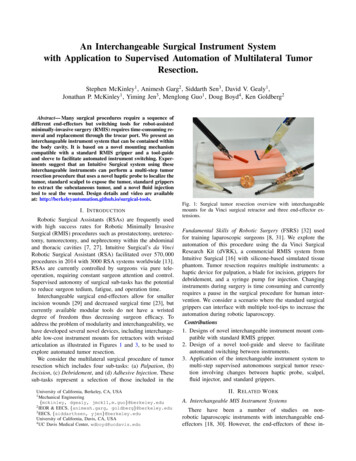
Fig. 6: Changing tools within the body cavity could reduce surgical time. In this configuration the blue arm carries a new tool into thesurgical workspace, the orange arm interfaces with the tool and carries it to the point of use.needle (seen in Figure 1(c)), a flexible catheter assembly,and a drive motor assembly mounted to the upper portion ofthe dVRK arm behind the sterile barrier. The Fluid Injectorprecision constraint is guided a theoretical dose volume ofsurgical glue (6 uL dose for each 2 mm of wound closure)based on [21]. Injection force is provided by a Haydon-Kerk21F4AC-2.5 linear actuator, powered by Allegro’s A4988micro-stepping bipolar stepper motor driver, and controlledby an Arduino Pro Mini 328 microcontroller. Syringes upto 10 mL in volume are carried by a 3D-printed enclosurealong a linear stage which is mounted to the RSA arm.Palpation: The dVRK retractor manipulates a palpationprobe (as shown in Figure 3(d)) affixed to a modularinstrument-tip mount to search for inclusions within a tissuephantom. The dVRK slides the lubricated end effector of theprobe over the surface of the tissue in eight parallel passeswhile the end-effector deflection is recorded by the ROSnode. Each parallel pass covers the entire 150 mm lengthof the tissue phantom (details in [22]). In each palpationpass the relatively stiff tumor causes a local maxima in endeffector displacement indicating the position of the tumor.Robot position data associated with the probe deflection datais used to filter out noisy data near the edges of the tissuewhere the probe loses contact with the surface of the tissue.In Figure 7(a), a haptic probe is shown palpating a fleshphantom; the position estimate of the underlying tumor isshown in the inset.Incision: The surgical retractor is prompted to closeand the palpation probe is detached and replaced with aclevis-mounted type-15 scalpel shown in Figure 1(b). Alinear incision is made in the cutaneous phantom at a fixedoffset from the estimated location of the tumor to createa retractable flap. The incision is performed in 1 cm linearslicing motions rather than incising continuously in onesingle pass because of friction at the blade-silicone interface.Once all the segments are complete, a finishing pass ismade along the full length of the incision to ensure a singlecontinuous incision.Without jaw articulation, this instrument is used to cut onlyin lines parallel to the ‘y’ axis. A third redesign allows forfull articulation (similar to the mount shown in Figure 3(e)).Debridement - Retraction and Resection: The next stepin the pipeline is Debridement: after removing the clevismounted scalpel, the left retractor grasps the cutaneous flapcreated during incision by moving to a pose below thesurface of the tissue and closing the jaws then retractingthe skin to reveal the tumor. The right arm approaches thetumor and uses repeated grasping-and-retracting motions toincrementally resect the tumor from the subcutaneous tissuebefore removing it from the workspace. Depth of each armis controlled as offsets from the surface plane created duringindexing.Injection: In the final step, the clevis-mounted injectortip (shown in Figure 1(c) connected to the Fluid InjectionDevice shown in is affixed to the surgical retractor on theright. The left surgical retractor then restores the skin flap toits original location before opening its jaws and depressingthe cutaneous layer to stabilize the wound. The right arm usesthe Fluid Injector to seal the incision with surgical adhesive.The needle tip passes over the incision at a constant rate asthe externally mounted syringe pump injects the adhesive tofacilitate uniform coverage of the incision site.Design of Tissue Phantoms: Tissue phantoms as shownin Figure 7 were created for testing. A cylindrical tumor ofSilicone Rubber (thickness 3 mm; Shore hardness 70A) wascoated in Vaseline and placed in the bottom of a 100 mmlong, 50 mm wide, 20 mm deep Delrin mold prior to casting.Silicone Rubber Ecoflex 00-30 (Smooth-On) was cast intothe mold to create subcutaneous tissue. After setting, thesubcutaneous phantom was demolded and inverted. A cutaneous phantom was created using a stiffer (shore hardness2A) DragonSkin 10 Medium Silicone Rubber (Smooth-On).Opaque pigmentation was achieved using a 0.5% by volumeaddition of Oil Pigment (Winton Oil Colour, Flesh Tint). Thedermal layer was cast at a thickness of 1 mm into a Delrinmold (width 60 mm and length 100 mm). Upon solidification, the dermal phantom was overlaid on the subcutaneousphantom to create the final tissue phantom setup.
Fig. 7: An autonomous simulated-tumor resection was performed using our suite of interchangeable instrument-tips and the da Vinci8 mm Needle Driver; the dVRK performed a) Palpation with a haptic probe, b) Incision using a scalpel, c) Debridement using the NeedleDrivers, and d) Injection of a surgical adhesive. Full video of the task is available at: dVRK Hardware and Software: We use the IntuitiveSurgical da Vinci Research Kit (dVRK) as described in [25]along with open-source electronics and software developedby WPI and Johns Hopkins University [16]. The softwaresystem is integrated with ROS, and controls robot pose inCartesian space by interpolating between requested points.Our manually created finite state machine consists of foursegments with a manual tool change occurring between eachas described in Figure 7.VI. E XPERIMENTAL R ESULTSTumor Resection End-to-End Performance: The end-toend tumor resection was repeated ten times with no priorknowledge of tumor location. Each phantom had a skinphantom layer of thickness (1 mm /- 0.25 mm), tumorphantom 25 mm in length and 3 mm in diameter. Successwas determined based on a complete tumor removal andwound closure. During trial 1 and trial 6, the position ofthe tumor was incorrectly estimated by the palpation proberesulting in respective failures in Debridement and Incision.In trial 4 and 7, the left retractor failed to grasp the dermalphantom fully and the tumor was not uncovered during skinretraction. In trial 8, the tumor was not fully resected fromthe flesh phantom during Debridement. Five of the ten trialswere successful.VII. D ISCUSSION AND F UTURE W ORKThis paper describes an interchangeable instrument systemthat can be contained within the body cavity. It is basedon a novel mounting mechanism compatible with a standard RMIS gripper and tool-guide and sleeve to facilitateautomated instrument switching. We evaluated a prototypeof the system on the dVRK with da Vinci Classic LargeNeedle Driver instruments. Experiments suggest that thisinterchangeable instrument system can perform a multistep tumor resection procedure that uses a novel hapticprobe to localize the tumor, standard scalpel to exposethe tumor, standard grippers to extract the subcutaneoustumor, and a novel fluid injection tool to seal the wound.In future work we will perform additional experimentswith tumor resection and other surgical procedures. Designfiles and fabrication instructions are available online ols/.AcknowledgementsThis research was performed in the CAL-MR (Center forAutomation and Learning for Medical Robotics) and in UCBerkeley’s Automation Sciences Lab under the UC BerkeleyCenter for Information Technology in the Interest of Society(CITRIS) ”People and Robots” Initiative: (robotics.citrisuc.org). This work was supported in part by the U.S. National Science Foundation under NRI Award IIS-1227536:Multilateral Manipulation by Human-Robot CollaborativeSystems; and by Google, Cisco, a major equipment grantfrom Intuitive Surgical and by generous donations fromAndy Chou and Susan and Deepak Lim. We also thankPieter Abbeel, Allison Okumura, W. Doug Boyd, MD, SimonDiMaio, Jeff Mahler, Michael Laskey, Zoe McCarthy, andFlorian T. Pokorny who provided helpful feedback.R EFERENCES[1] “Intuitive Surgical, EndoWrist /Single-Site Instrument & AccessoryCatalog.” [Online]. Available: http://www.intuitivesurgical.com/products/871145 Instrument Accessory %20Catalog.pdf[2] R. Alterovitz and K. Goldberg, Motion Planning in Medicine: Optimization and Simulation Algorithms for Image-guided Procedures.Springer, 2008.[3] J. Alvarez, G. Stahler, F. Barbagli, and C. Carlson, “Endoscopicrobotic catheter system,” Jan. 20 2011, US Patent App. 12/504,559.[4] ST79-Comprehensive guide to steam sterilization and sterility assurance in health care facilities,, ANSI/AAMI Std. ST79:2010/A4:2013.[5] C. E. Attinger, E. Bulan, and P. A. Blume, “Surgical Debridement:The Key to Successful Wound Healing and Reconstruction,” Clinicsin podiatric medicine and surgery, vol. 17, no. 4, p. 599, 2000.[6] R. A. Beasley, “Medical Robots: Current Systems and ResearchDirections,” Journal of Robotics, vol. 2012, 2012.[7] A. Darzi and Y. Munz, “The impact of minimally invasive surgicaltechniques,” Annu. Rev. Med., 2004.[8] G. Dulan, R. V. Rege, D. C. Hogg, K. M. Gilberg-Fisher, N. A.Arain, S. T. Tesfay, and D. J. Scott, “Developing a Comprehensive,Proficiency-based Training Program for Robotic Surgery,” Surgery.[9] Y. Fong, W. Jarnagin, K. Conlon, R. DeMatteo, E. Dougherty, andL. Blumgart, “Hand-assisted laparoscopic liver resection: Lessonsfrom an initial experience,” Archives of Surgery, 2000.[10] D. C. Friedman, J. Dosher, T. Kowalewski, J. Rosen, and B. Hannaford, “Automated tool handling for the trauma pod surgical robot,”in ICRA, 2007.[11] M. Granick, J. Boykin, R. Gamelli, G. Schultz, and M. Tenenhaus,“Toward a Common Language: Surgical Wound Bed Preparation andDebridement,” Wound repair and regeneration, 2006.[12] D. Hu, Y. Gong, B. Hannaford, and E. J. Seibel, “Semi-autonomoussimulated brain tumor ablation with ravenii surgical robot usingbehavior tree,” in IEEE Int. Conf. Robotics and Automation, 2015.[13] Intuitive Surgical, “Annual report 2014.” [Online]. Available: l?c 122359&p irol-IRHome
[14] Y. Jung, G. Bauer, and J. A. Nolta, “Concise review: Induced pluripotent stem cell-derived mesenchymal stem cells: progress toward safeclinical products,” Stem cells, vol. 30, no. 1, pp. 42–47, 2012.[15] J. M. Karp and G. S. L. Teo, “Mesenchymal stem cell homing: thedevil is in the details,” Cell stem cell, vol. 4, no. 3, pp. 206–216, 2009.[16] P. Kazanzides, Z. Chen, A. Deguet, G. S. Fischer, R. H. Taylor, andS. P. DiMaio, “An open-source research kit for the da vinci surgicalsystem,” in IEEE Int. Conf. Robotics and Automation (ICRA), 2014.[17] B. Kehoe, G. Kahn, J. Mahler, J.-H. Kim, A. Lee, K. Nakagawa,S. Patil, W. D. Boyd, P. Abbeel, and K. Goldberg, “Autonomousmultilateral debridement with the raven surgical robot,” in ICRA, 2014.[18] T. Kheir, “Multi-purpose minimally invasive instrument that uses amicro entry port,” Feb. 23 2010, uS Patent 7,666,181.[19] J. Konstantinova, A. Jiang, K. Althoefer, P. Dasgupta, andT. Nanayakkara, “Implementation of tactile sensing for palpation inrobot-assisted minimally invasive surgery: A review,” Sensors Journal,IEEE, 2014.[20] M. Kranzfelder, C. Staub, A. Fiolka, A. Schneider, S. Gillen, D. Wilhelm, H. Friess, A. Knoll, and H. Feussner, “Toward increased autonomy in the surgical or: needs, requests, and expectations,” Surgicalendoscopy, 2013.[21] P. Losi, S. Burchielli, D. Spiller, V. Finotti, S. Kull, E. Briganti,and G. Soldani, “Cyanoacrylate surgical glue as an alternative tosuture threads for mesh fixation in hernia repair,” Journal of SurgicalResearch, 2010.[22] S. McKinley, A. Garg, S. Sen, R. Kapadia, A. Murali, K. Nichols,S. Lim, S. Patil, P. Abbeel, A. M. Okamura, and K. Goldeber, “Adisposable haptic palpation probe for locating subcutaneous bloodvessels in robot-assisted minimally invasive surgery,” in CASE, 2015.[23] D. J. Miller, C. A. Nelson, and D. Oleynikov, “Shortened OR time anddecreased patient risk through use of a modular surgical instrumentwith artificial intelligence,” Surgical endoscopy, vol. 23, 2009.[24] G. Moustris, S. Hiridis, K. Deliparaschos, and K. Konstantinidis,“Evolution of autonomous and semi-autonomous robotic surgicalsystems: a review of the literature,” T
An Interchangeable Surgical Instrument System with Application to Supervised Automation of Multilateral Tumor Resection. Stephen McKinley1, Animesh Garg2, Siddarth Sen3, David V. Gealy1, Jonathan P. McKinley1, Yiming Jen3, Menglong Guo1, Doug Boyd4, Ken Goldberg2 Abstract—Many