Transcription
TIP 0404-55ISSUED – 2001REVISED – 2006REVISED -- 2018 2018 TAPPIThe information and data contained in this document wereprepared by a technical committee of the Association. Thecommittee and the Association assume no liability or responsibilityin connection with the use of such information or data, includingbut not limited to any liability under patent, copyright, or tradesecret laws. The user is responsible for determining that thisdocument is the most recent edition published.Performance evaluation techniques for paper machineliquid ring vacuum systemsScopeThis document describes general techniques for the evaluation of performance of liquid ring vacuum systems on papermachines. Its intent is to give papermakers a procedure for seeking and eliminating bottlenecks in liquid ring vacuumsystems and implementing optimum vacuum performance by reducing operating costs and increasing productivity.Definitions1.2.3.ACFM: Actual Cubic Feet per Minute. The measurement of vacuum pump volumetric flow at a vacuum levelOrifice Test: Vacuum pump testing method. See TAPPI TIP 0420-12Dwell Time: The amount of time it takes for the felt to travel from the leading edge to the trailing edge of a suction boxslot.MaterialsThe following materials are recommended for following the guidelines: Flat plate orifice testing equipment, described in TIP 0420-12 Analog (with a needle) vacuum gaugesSafety precautionsCaution should be taken when performing the orifice plate test. Vacuum may pull the tester’s finger into the orifice hole.ContentVacuum Pump TestingLiquid ring vacuum pumps are the key components of every vacuum system. Efficient performance is necessary formaintaining optimum airflow and vacuum levels throughout the paper machine. Performance should be monitored to ensurethat liquid ring vacuum pumps are consuming minimum energy to remove maximum water from the paper sheet or felts. Themost effective liquid ring vacuum pump performance test that can be performed in the paper mill is the flat plate orifice testmethod. This test must be done with the testing of the liquid ring vacuum pump isolated from the paper machine.To summarize, an orifice plate or plates are placed on the liquid ring vacuum pump inlets. These plates contain a series ofbored holes that are calibrated to allow specified air flows over the entire range of vacuum levels of a liquid ring vacuumpump. This test gives the papermaker performance data to compare to the manufacturer’s performance curve of the liquidring vacuum pump and to insure that necessary air flow requirements are being met. The orifice plate test method isdescribed in TIP 0420-12. Most liquid ring vacuum pump suppliers offer pump field tests as a service.A boroscope can be used to visually inspect mineral or pulp deposits and corrosion or erosion of rotor and cone surfaces. Arough estimation of liquid ring vacuum pump capacity can be determined by evaluating these internal conditions. Thismethod allows for an easier, although less accurate determination of liquid ring pump efficiency.TIP Category: Automatically Periodically Reviewed (Ten Years)
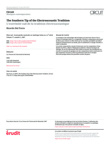
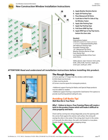
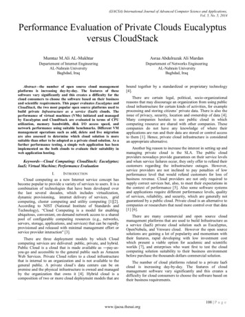
TIP 0404-55Performance evaluation techniques / 2for paper machine vacuum systemsDimensions, fixed and variableAll formula derived dimensions of the vacuum system in this TIP are calculated for design and manufacturing as fixed.There are also four very important variable dimensions that change with time. They are:1. The clearance of rotor vane to cone surface which increases with time.2. The radial length of the water piston in the seal segment from the inner housing wall land area to the cone surfaceland area which is controlled by the seal water linear regulating control valve.3. The amount of seal water flow, gpm or liters per minute to develop maximum stable vacuum develops variablethicknesses of water between the inner vane surfaces and the cone outer surface. This very important dimension ofseal water compresses gases from leaking backward to following compression chambers between vanes.4. The seal water control valve opening which changes to develop maximum stable vacuum.1. Rotor Vane and Cone clearance in the Seal SegmentThe rotor vane to cone surface clearance distance in the seal segment is affected by corrosion – erosion and increases withtime. This clearance is the most important vacuum system dimension, because with time, cast iron rotor to cone clearancewidens from erosion of iron oxide (rust) and decreases new inlet vacuum airflow performance continually over years’ time.An iron rotor-cone pump can easily lose 30% to 50% of original capacity over ten to twenty years, by high pressure dischargegas from the discharge segment slipping into the inlet segment and blocking new inlet gas from entering the pump. Over tenyears, stainless steel holds this clearance by forming dynamically hardened chromic oxide, and may lose only 5% to 10% ofvacuum airflow performance.Pump Inlet (Vacuum Gas)Pump Inlet (Vacuum Gas)ConeInletPortConeInletPortStainlessConeRusty ConeVaneslip(Wasteful)SealSegmentStainless Rotor VaneSealSegmentPump Discharge (Pressuregas higher than atmospheric)A Rusty WornIron RotorVanePump Discharge(Pressure gas higherthan atmospheric) Note: The above copyrighted images are used with consent of Vooner FloGard Corporation , dba Vooner Paper Machinery.2.The Radial length of the water piston in the seal segment must equal the distance from the inner surface of the housingland area to the cone surface in the seal segment. As shown above, if the length of the piston is short then Vaneslip willoccur. For each side of the liquid ring vacuum pump, increasing seal water flow with two regulating valves (linearrelation of % open relates to % flow) will increase the length of these pistons.3.The sufficient variable amount of seal water needed is described as, “enough seal water to develop a maximum stablevacuum.” To see “maximum stable vacuum” two analog (with needle) vacuum gages need to be read for each end of thepump as the regulating valves are changed. If the needle flutters, then there is not enough seal water and the regulatingvalve needs to be opened slowly until the needle is “pegged” or still. If you continue to open the regulating valve and nomore vacuum is achieved, then there is too much water, and the regulating valve can be turned back to reduce flow untilthe needle just begins to flutter again, then increase again slightly for maximum stable vacuum.
3 / Performance evaluation techniques4.TIP 0404-55Variable control of seal water flow is a significant component (yet often overlooked) to the successful operation of theliquid ring vacuum pump for improving vacuum system productivity and reliability:a. No control device usually means too much water is used in the pumpb. An “on – off” shut off ball valve gives no variable control, only on or offc. A single orifice disc in a union joint is set for one nominal flow probably recommended by the manufacturertechnical data sheet. This flow rate is given for supply planning.d. A linear (% open relates to % of flow) regulating valve allows setting optimal seal water flow rate from whenthe pump is new to making adjustments for opening of the vane to cone surface over as is gradually will changeover years of service.Evaluating Liquid Ring Pump Tests and Performance EstimatesCapacity comparisons are made at the actual rotational speed (RPM) of the liquid ring vacuum pump. Liquid ring pump testresults should be compared to original capacity at the optimum vacuum level for each application. By dividing the actualtested capacity, m3/hr (ACFM), by the capacity, m3/hr (ACFM), shown on the liquid ring vacuum pump manufacturer’sperformance curve, the % of original capacity obtained. For example, if a liquid ring vacuum pump designed to have acapacity of 5,950 m3/hr (3,500 ACFM) at 380 mm Hg (15 inches Hg) vacuum only tested at 5,100 m3/hr (3,000 ACFM) at380 mm Hg (15 inches Hg) vacuum, this pump is said to be at eighty-six percent (86%) of original capacity at that vacuumlevel.Calculating Vacuum Liquid Ring Vacuum Pump Operating CostsThe two primary operating costs associated with liquid ring vacuum pumps are energy and seal water. Use Equation 1 tocalculate annual energy costs for liquid ring vacuum pump operation.Equation 1: Ea kW x UR x hr x daywhere: Ea Annual energy costkW pump kilowatt usage from curve UR utility rate at mill in /kW hrhr operation hours per dayday operation days per year Ea BHP x 0.746 x UR x hr x daywhere: Ea Annual energy costBHP pump horsepower from curve UR utility rate at mill in /kW hrhr operation hours per dayday operation days per yearTo calculate the annual seal water costs for liquid ring vacuum pump operation, use Equation 2.Equation 2: SWa l/min x 60 x SWr x hr x daywhere: SWa Annual Seal Water Costl/min seal water flow SWr seal water cost rate, /1000 litershr operation hours per dayday operation days per year SWa gpm x 60 x SWr x hr x daywhere: SWa Annual Seal Water Costgpm seal water flow SWr seal water cost, /1000 gallonshr operation hours per dayday operation days per yearAfter calculating the energy and seal water costs for each liquid ring vacuum pump, they can be summed to give the total costfor operating the liquid ring vacuum pumps for the entire machine.Calculating Wasted Operating CostsAs liquid ring vacuum pumps lose capacity due to erosion or corrosion on the rotor and cone surfaces, they continue toconsume the same horsepower and require the same seal water flow as if the pump were new. The result is wasted energyand water costs. When evaluating total liquid ring vacuum system operating costs, it is important to establish how much ofthe operating costs are being wasted on inefficient liquid ring vacuum pumps. From the example above, the 86% capacitypump is wasting 14% of these operating costs. From the performance curve it is found that the 86% capacity pump isconsuming 215 kW (160 BHP). Because the pump is producing 14% less capacity as a new pump, it is wasting 14% of thepower or 30.1 kW (22.4 BHP). This principle is also true for the seal water flow. If the liquid ring pump mentioned requires227 l/min (60 gpm) of seal water flow for operation, 32l/min (4 gpm) is being wasted on inefficiency.
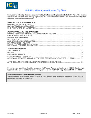
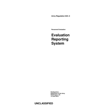
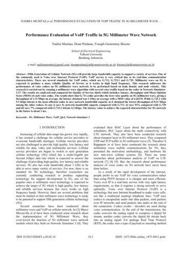
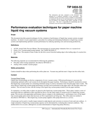
TIP 0404-55Performance evaluation techniques / 4for paper machine vacuum systemsThe next step is to calculate the wasted operating costs by using Equations 3 and 4.Equation 3: Ewa Ea x (1-%OC)where: Ewa Annual Wasted Energy Cost Ea annual energy costs from Eq.1%OC liquid ring vacuum pump % original capacity from pump testEquation 4: SWwa SWa x (1-%OC)where: SWwa annual wasted seal water cost SWa annual seal water costs from Eq.2%OC liquid ring vacuum pump % of original capacity from pump testThe following figure shows vacuum pump drive horsepower is the same with a new and an old pump but that the worn pumpsupplies much lower volume. (6). This data was derived from Vooner’s variable speed test stand, Charlotte, NC. The equalamount of power, shown for new and worn pumps, was attributed to increasing the seal water for maximum stable vacuum.For extreme poor rotor – cone clearances, increasing the seal water 100% ended up pushing the excess water out thedischarge port and increased the power consumption by 10%.Note: The above copyrighted figure is used with consent of Vooner FloGard Corporation , dba Vooner Paper Machinery.
5 / Performance evaluation techniquesTIP 0404-55More detail is available regarding vacuum pump operating cost in “The Full Operating Costs of LiquidRing Vacuum Pumps” located in the 1995 TAPPI Engineering Conference Proceedings.Suction (Uhle) Box SizingThe heart of the vacuum dewatering system is the vacuum box itself. The system design starts at the box. This is where theforce of atmospheric pressure pushes itself and entrained water through saturated fabric, and is reduced to vacuum (pressureless than atmospheric) as it enters the box. Properly sized felt suction or uhle boxes according to this TIP are critical toinsure that felt de-watering is maximized. There are two sizing parameters that should be evaluated: box diameter and slotwidth.Box DiameterThe velocity of the water/air mixture flowing through the felt suction box should be below 1,065 m/min (3,500 ft/min). Byknowing the airflow, m3/hr (ACFM), supplied from the vacuum pump, minimum box diameters can be calculated usingEquation 5.Equation 5:Minimum Box Diameter (mm) 3flow( m / hr ) 19.89Minimum Box Diameter (inch) flow( ACFM ) 0.052Slot WidthSuction box slot widths should be sized to maintain a dwell time of 2 to 4 milliseconds. Dwell time is the amount of timethat it takes for the felt to travel across the slot. Maintaining a dwell time within this range will allow enough time for thewater in the felt to travel through the felt and into the suction box. If the dwell time is greater than 4 milliseconds, felts willtend to drag across the box and could experience premature wear. An exception to the 2 – 4 millisecond dwell time“standard” is on tissue machines. Many tissue machines operate well with only 1.0 – 1.5 ms of uhle box dwell time. This isbecause felts on tissue machines often operate at much higher moisture levels than paper or board.Calculating correct slot width sizing base on a specific dwell time is done using Equation 6:Equation 6:Slot Width (mm) Dwell time (ms) x machine speed (m/min)60Slot Width (inch) Dwell time (ms) x machine speed (ft/min)5000Slot widths should not be less than 13 mm (0.5 inch) or greater than 25 mm (1.0 inch). If the slot width is calculated to begreater than 25 mm (1.0 inch), multiple slots should be used.Liquid Ring Vacuum Pump SizingThere are several types of vacuum applications on the wet end of a paper machine. The most common applications are asfollows:Fourdrinier MachineApplicationPurpose (with vacuum)Wire (Flat) Boxes Consolidate sheet by high volume water removalCouch RollCo
The following figure shows vacuum pump drive horsepower is the same with a new and an old pump but that he worn pump t supplies much lower volume. (6). This data was derived from Vooner’s variable speed test stand, Charlotte, NC. The equal amount of power, shown for new and worn pumps, was attributed to increasing the seal water for maximum stable vacuum. For extreme poor rotor – cone .