Transcription
Youth Explore Trades SkillsDesign and Drafting – 2D DrawingIntroduction to Title Blocks (Architectural Board Drafting)DescriptionIn this activity the teacher will demonstrate the use of board drafting tools and equipment tocreate a title block. A title block is comprised of the information boxes found on the bottom righthand corner of a drawing, which indicate drawing details such as the title, author name, scale,and date the drawing was created.This is an introductory activity designed to be completed prior to any other board drawingactivities. It will cover basic standards in precision drawing techniques, pencil hardness/selection, and lettering.Lesson ObjectivesThe student will be able to: Complete a board and page setup Use tools appropriately to draw a title block Differentiate pencil hardness relative to line weight, and select a pencil accordingly Understand and identify architectural measurement standards (imperial units ofmeasurement) Use basic line weight techniques Identify and implement lettering techniquesAssumptionsThe teacher will have a fundamental knowledge of drafting tools and equipment (see DraftingDictionary Activity Plan).The student will: Have a basic knowledge of drafting tools and equipment Have a foundational understanding of how to appropriately use drafting equipmentTerminologyBorder lines: thick, dark lines used to create a solid border around a blank page.Drafting board: a flat, smooth surface usually covered in vinyl to which paper is affixed. Thedrafting board has square, parallel edges that allow a T-square to slide easily.Drafting brush: used to sweep away debris from a drawing so the full drawing is not smeared.Eraser shield: a micro-thin piece of metal with cut-outs that allow the user to erase detailedsections of a drawing without erasing the rest of the drawing.This work is licensed under a Creative Commons Attribution-NonCommercial-ShareAlike 4.0 International License unless otherwise indicated.
Introduction to Title Blocks (Architectural Board Drafting)Design and Drafting – 2D DrawingGuide lines: thin, light lines drawn using the lettering guide for evenly spaced letters.Layout lines: very light lines used to lay out measurements before those measurements aredrawn in heavy, dark lines (border lines).Lettering guide: used to assist in the drawing of uniform lines to draw consistent, evenly spacedlettering.Line weight: the thickness and darkness of drawn lines.Masking tape (drafting dots): holds drawing paper and/or vellum to the drafting board so thepaper does not shift while drawing.Pencil: a drawing utensil with a mechanical or solid core (lead). Leads range from hard to soft:6H, 4H, 2H, H, HB, 2B, 4B, 6B. H is very hard with a fine point and B is extremely soft with ablunt point. A hardness of 2H is recommended for these activities.Precision drawing: the act of creating drawings with specialized tools and equipment.Steel rule: a straightedge made of rigid material and divided into specific increments, found bothin metric and imperial units.Title block: comprised of the information boxes found on the bottom right-hand corner of adrawing, the title block indicates drawing details such as the title, author name, scale, and date adrawing was created.Triangles (right angle and isosceles): drafting guides made of hard, clear plastic that are used todraw lines at vertical and set angles (45 –90 –45 , 30 –60 –90 ).T-square: a precision drawing instrument that is used as a guide with other drafting equipment.The T-square has a 90 angle where the head and blade attach.Estimated Time30–60 minutesRecommended Number of Students20, based on BC Technology Educators’ Best Practice GuideFacilities Regular classroom space with desks/chairs for all students, a projector with computer andspeakers, and Internet access Drafting boards (any large enough smooth, flat surface will also work)Tools T-square Steel rule Triangles (right angle and isosceles)2Youth Explore Trades Skills
Design and Drafting – 2D DrawingIntroduction to Title Blocks (Architectural Board Drafting) Eraser shield Drafting brush Masking tape (drafting dots) Drafting board Lettering guide Mechanical pencil or drafting pencil with 2H lead (most versatile for drawing at this stage)Materials Handout for students with instructions (suggestion: develop a handout using theinstructions from the teacher-led activity that follows).Resources Drafting Dictionary Activity PlanStudent Activity1. Complete title block drawing.2. Fill in title block with appropriate information as noted below.TITLE OF EXERCISENAME OF DRAWINGSTUDENT NAMEDATESCALE OF DRAWINGPAGEExtension ActivityHave students create multiple title block pages for further use in subsequent exercises.Assessment Student participation in discussion/demonstration Completion of drawing with overall neatness:–– Lines are drawn correctly.–– Border lines cross to ensure closed corners.–– Lettering is done to a high quality (all uppercase).–– Title block is filled out correctly with appropriate information.Youth Explore Trades Skills3
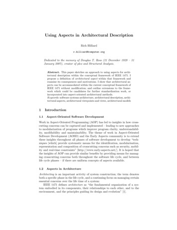
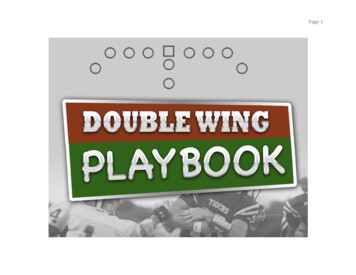
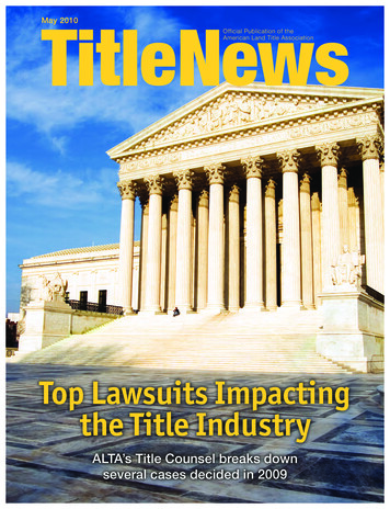
Introduction to Title Blocks (Architectural Board Drafting)Design and Drafting – 2D DrawingTeacher-led Activity1. Gather all materials listed above.2. Using the T-square and masking tape and/or drafting dots, align blank paper to your draftingboard and securely tape down (Figure 1).Figure 1—Secure paper to board3. Using the imperial ruler, mark out lines with your pencil around the entire page at ½" from theoutside edge (Figure 2). These lines should be small, should align with the direction of thepage, and should be very light (layout lines).Figure 2—Mark off border4Youth Explore Trades Skills
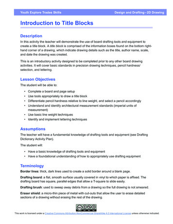
Design and Drafting – 2D DrawingIntroduction to Title Blocks (Architectural Board Drafting)4. Using the T-square and right angle triangle, join these lines to create a border around theentire page (Figure 3). These lines should be solid, dark lines with no breaks (border/titleblock lines).Note: The border lines should cross over each other to ensure closed corners (Figure 4), butthey should not extend to the edges of the page.Figure 3—Draw borderFigure 4—Closed cornerYouth Explore Trades Skills5
Introduction to Title Blocks (Architectural Board Drafting)Design and Drafting – 2D Drawing5. Mark a point ¾" above the bottom border line (Figure 5) and draw a layout line joining the leftand right vertical border lines.Figure 5—Measure layout line ¾" horizontally above bottom border6. Repeat step 5, measuring up another ¾" from the line you just drew (Figure 6).Figure 6—Measure a second horizontal layout line ¾" from the line drawn instep 5 (or 1½" from the bottom border!6Youth Explore Trades Skills
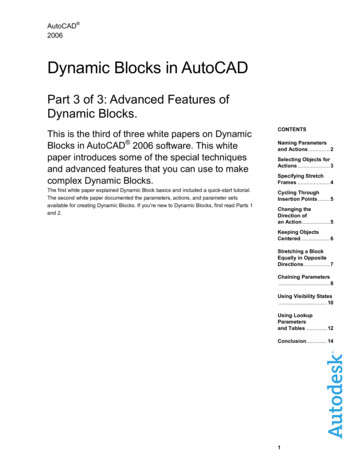
Design and Drafting – 2D DrawingIntroduction to Title Blocks (Architectural Board Drafting)7. From the vertical border line on the right-hand side of the page, measure in 2½" toward theleft (Figure 7) and use layout lines to mark in the title blockFigure 7—Measure in 2 ½" from vertical border line8. Divide the blocks in the small section at ⅜". You should end up with four small sections thatare ⅜" high and 2½" wide (Figure 8).Figure 8—Small sections divided at 3/8" height (right)Youth Explore Trades Skills7
Introduction to Title Blocks (Architectural Board Drafting)Design and Drafting – 2D Drawing9. Demonstrate how to use a lettering guide aligned with the T-square (Figure 9) to draw lightguide lines to fill in the title block (Figure 10).Figure 9—Using a lettering guideFigure 10—Letter guide lines10. Fill in the title block with the appropriate information. Remind students that draftingconvention requires that all lettering be done in CAPITALS.Appendix Acknowledgment Camosun College. Trades Access Common Core: Competency D-3: Read Drawings andSpecifications (pp. 25–33). The Trades Access Common Core resources are licensed underthe Creative Commons Attribution 4.0 Unported Licence (http://creativecommons.org/licenses/by/4.0/), except where otherwise noted.8Youth Explore Trades Skills
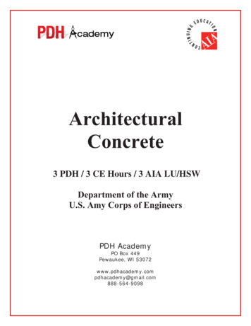
Design and Drafting – 2D DrawingIntroduction to Title Blocks (Architectural Board Drafting)COMpETENCy D-3: READ DRAwiNgS AND SpECifiCATiONSLEARNiNg TASk 2AppendixLEARNING TASK 2Describe lines, lettering, and dimensioning indrawingsThe purpose of engineering drawings is to convey objective facts, whereas artistic drawingsconvey emotion or artistic sensitivity in some way.Engineering drawings and sketches need to display simplicity and uniformity, and they must beexecuted with speed. Engineering drawing has evolved into a language that uses an extensiveset of conventions to convey information very precisely, with very little ambiguity.Standardization is also very important, as it aids internationalization; that is, people fromdifferent countries who speak different languages can read the same engineering drawing andinterpret it the same way. To that end, drawings should be as free of notes and abbreviations aspossible so that the meaning is conveyed graphically.Line styles and typesStandard lines have been developed so that every drawing or sketch conveys the same meaningto everyone. In order to convey that meaning, the lines used in technical drawings have both adefinite pattern and a definite thickness. Some lines are complete and others are broken. Somelines are thick and others are thin. A visible line, for example, is used to show the edges (or“outline”) of an object and to make it stand out for easy reading. This line is made thick and dark.On the other hand, a centre line, which locates the precise centre of a hole or shaft, is drawn thinand made with long and short dashes. This makes it easily distinguishable from the visible line.When you draw, use a fairly sharp pencil of the correct grade and try to maintain an even,consistent pressure to make it easier for you to produce acceptable lines (Figure 1). Study theline thicknesses (or “line weights”) shown in Figure 2 and practise making them.SketchingTechnical9H 8H 7H 6H 5H 4H 3H 2H HFHBB2B 3B 4B 5B 6B 7B 8B 9BHardnessBlacknessFigure 1 — Lead grade and usageYouth Explore Trades Skills“Download for free at http://open.bccampus.ca/find-open-textbooks/”9
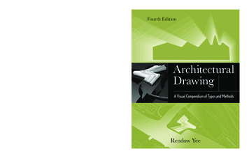
Introductionto TitleBlocks(ArchitecturalBoard Drafting)COMpETENCyD-3: READDRAwiNgSAND SpECifiCATiONSDesign and Drafting – 2DDrawingLEARNiNgTASk 2In computer drafting, the line shape remains the same, but line thickness may not vary as itdoes in manually created drawings. Some lines, such as centre lines, may not cross in the samemanner as in a manual drawing. For most computer drafting, line thickness is not important.TypeObject lineMargin lineHidden body linePhantom lineWeightLineDescriptionSolid line to show visible shape, edges, and outlines.HeavyBroken line of long and short dashes to show hiddenobject lines not visible to the eye.MediumBroken line of short dashes to show alternatepositions or movement of a part.LightUnbroken lines arranged in a pattern, usuallystraight and at a 45º diagonal.Section lineSteelCopper/BrassLeadCast iron/General purposeLightProjection lineLightUnbroken lines that extend away from the object orfeature for emphasis.Centre lineLightBroken line of long and short dashes to show thecentre of an object.LightExtension lines are small lines that extend outwardfrom an object or feature. Dimension lines spanbetween the extension lines with arrowheads and agiven dimension.Extension line/Dimension lineLeader lineCutting planelineBreak lines forwood and metal25 mmUnbroken line usually drawn at an angle often witha “dogleg” and an arrowhead. A dot is used in placeof an arrowhead where a surface is referenced.Usually accompanied by a label.LabelLightAAHeavyBroken line of one long and two short dashes toshow an imaginary cross-section. The arrowheadsshow the direction from where the cross-section isviewed. A corresponding image will show the viewof A.Unbroken freehand or straight zig-zag lines to abbreviate longer spans of wood or metal.HeavyCurled lines to abbreviate a longer span of pipe.Break lines forpipingHeavyFigure 2 — Weights of lines10“Download for free at outh Explore Trades SkillsTRADES ACCESS—COMMON CORE
Design and– 2D DrawingIntroduction to Title Blocks (ArchitecturalBoardTASkDrafting)COMpETENCyD-3: DraftingREAD DRAwiNgSAND SpECifiCATiONSLEARNiNg2To properly read and interpret drawings, you must know the meaning of each line andunderstand how each is used to construct a drawing. The ten most common are often referredto as the “alphabet of lines.” Let’s look at an explanation and example of each type.Object linesObject lines (Figure 3) are the most common lines used in drawings. These thick, solid lines showthe visible edges, corners, and surfaces of a part. Object lines stand out on the drawing andclearly define the outline and features of the object.Object lineFigure 3 — Object linesHidden linesHidden lines (Figure 4) are used to show edges and surfaces that are not visible in a view. Theselines are drawn as thin, evenly spaced dashes. A surface or edge that is shown in one view withan object line will be shown in another view with a hidden line.Figure 4 — Hidden linesYouth Explore Trades SkillsTRADES ACCESS—COMMON CORE“Download for free at 1
Introductionto TitleBlocks(ArchitecturalBoard Drafting)COMpETENCyD-3: READDRAwiNgSAND SpECifiCATiONSDesign and Drafting – 2DDrawingLEARNiNgTASk 2Centre linesCentre lines (Figure 5) are used in drawings for several different applications. The meaning ofa centre line is normally determined by how it is used. Centre lines are thin, alternating longand short dashes that are generally used to show hole centres and centre positions of roundedfeatures, such as arcs and radii. Arcs are sections of a circle, and radii are rounded corners oredges of a part. Centre lines can also show the symmetry of an object.rFigure 5 — Centre linesDimension and extension linesDimension and extension lines (Figure 6) are thin, solid lines that show the direction, length, andlimits of the dimensions of a part. Dimension lines are drawn with an arrowhead at both ends.Extension lines are drawn close to, but never touching, the edges or surface they limit. Theyshould be perpendicular, or at right angles, to the dimension line. The length of extension linesis generally suited to the number of dimensions they limit.DimensionDimension lineEnd marksExtension line62Object lineFigure 6 — Dimension and extension lines12“Download for free at outh Explore Trades SkillsTRADES ACCESS—COMMON CORE
Design and– 2D DrawingIntroduction to Title Blocks (ArchitecturalBoardTASkDrafting)COMpETENCyD-3: DraftingREAD DRAwiNgSAND SpECifiCATiONSLEARNiNg2Leader linesLeader lines (Figure 7) show information such as dimensional notes, material specifications, andprocess notes. These lines are normally drawn as thin, solid lines with an arrowhead at one end.They are bent or angled at the start, but should always end horizontal at the notation. Whenleader lines reference a surface, a dot is used instead of an arrowhead.Leader line (thin and solid)Flat bar 3 mm thickø8 2 holesR 20Copper plate this surfaceFigure 7 — Leader linesNote that the symbol ø is used to indicate a diameter rather than the abbreviation “DIA.” Thenumber that immediately follows this symbol is the diameter of the hole, followed by thenumber of holes that must be drilled to that dimension.Phantom linesLike centre lines, phantom lines (Figure 8) are used for several purposes in blueprints. Phantomlines are used to show alternate positions for moving parts and the positions of related oradjacent parts, and to eliminate repeated details. Phantom lines are drawn as thin, alternatinglong dashes separated by two short dashes.Youth Explore Trades SkillsTRADES ACCESS—COMMON CORE“Download for free at 3
Introductionto TitleBlocks(ArchitecturalBoard Drafting)COMpETENCyD-3: READDRAwiNgSAND SpECifiCATiONSDesign and Drafting – 2DDrawingLEARNiNgTASk 2Existing columnNew girderFigure 8 — Phantom linesCutting plane linesCutting plane lines (Figure 9) show the location and path of imaginary cuts made through partsto show internal details. In most cases, sectional views (or views that show complicated internaldetails of a part) are indicated by using a cutting plane line. These lines are thick, alternatinglong lines separated by two short dashes. The arrowheads at each end show the viewingdirection of the related sectional view. The two main types of cutting plane lines are the straightand the offset.Cutting plane line (thick with one long then two short dashes)AABSection A–ABSection B–BFigure 9 — Cutting plane lines14“Download for free at outh Explore Trades SkillsTRADES ACCESS—COMMON CORE
Design and– 2D DrawingIntroduction to Title Blocks (ArchitecturalBoardTASkDrafting)COMpETENCyD-3: DraftingREAD DRAwiNgSAND SpECifiCATiONSLEARNiNg2Section linesSection lines, also known as sectional lining, (Figure 10) indicate the surfaces in a sectionalview as they would appear if the part were actually cut along the cutting plane line. These aresolid lines that are normally drawn at 45 degree angles. Different symbols are used to representdifferent types of materials.Section lines (thin and solid)Section B–BFigure 10 — Section lines combined with cutting plane linesBreak linesBreak lines are drawn to show that a part has been shortened to reduce its size on the drawing.The two variations of break lines common to blueprints are the long break line and the shortbreak line (Figure 11). Long break lines are thin solid lines that have zigzags to indicate a break.Short break lines are thick, wavy solid lines that are drawn freehand. When either of these breaklines is used to shorten an object, you can assume that the section removed from the part isidentical to the portions shown on either side of the break.(thin and long with a zigzag)(thick and short, wavy freehand)Figure 11 — Break lineYouth Explore Trades SkillsTRADES ACCESS—COMMON CORE“Download for free at 5
Introductionto TitleBlocks(ArchitecturalBoard Drafting)COMpETENCyD-3: READDRAwiNgSAND SpECifiCATiONSDesign and Drafting – 2DDrawingLEARNiNgTASk 2Standard letteringThe letters and numbers on a drawing or sketch are as important as the lines. Scribbled,smudged, or badly written letters and numbers can become impossible to read. This may lead totime-consuming and costly errors. Lettering is necessary to describe: the name or title of a drawing when it was made the scale who sketched it the dimensions the special notations that describe the size the materials to be used the construction methodsThe American Standard Vertical letters (Figure 12) have become the most accepted style oflettering used in the production of manual drafting. This lettering is a Gothic sans serif script,formed by a series of short strokes.Font styles and sizes may vary in computer drafting. Note that all letters are written as capital(upper case) letters. Practise these characters, concentrating on forming the correct shape.Remember that letters and numbers must be black so that they will stand out and be easy toread. Lettering and figures should have the same weight and darkness as hidden lines.Title and drawing sizes 6 mm (¼")A B C D E F G H I J K LM N O P Q R ST UVWXY Z 0 1 2 3 4 5 6 7 8 9Dimension and notation sizes 3 mm (1 8")A B C D E F G H I J K LM N O P Q R S T U V WX Y Z 0 1 2 3 4 5 6 7 8 9Figure 12 — Standard lettering16“Download for free at outh Explore Trades SkillsTRADES ACCESS—COMMON CORE
Design and– 2D DrawingIntroduction to Title Blocks (ArchitecturalBoardTASkDrafting)COMpETENCyD-3: DraftingREAD DRAwiNgSAND SpECifiCATiONSLEARNiNg2AbbreviationsAbbreviations are commonly used to help simplify a drawing and conserve space. Althoughmany fields share common abbreviation conventions, there are also field- or trades-specificconventions that you will see as you become more specialized. Here is a common list ofabbreviations that are used on drawings. Each trade will have specific abbreviations from thislist, and therefore a set of drawings will usually include an abbreviation RHTanchor boltaboutauxiliarybolt circlebevel both endsbolt circle diameterbevel one endboth endsbaselinebench markbottombase plateblueprintblindcentre to centrecolumncouplingcarbon steelcomplete evationexternalface to faceflat faceflangefillet weldgaugegalvanizedheavyhex headhot rolledheat treatmentYouth Explore Trades SkillsTRADES ACCESS—COMMON COREHLS holesHSS hollow structural steelIDinside diameterINinchesINTinternalISOInternational Standards Org.KPkick plateLHleft handLATlateralLRlong radiusLGlongMBmachine boltMSmild steelMIN minimumMAX maximumMAT’L materialMISC miscellaneousNCnational courseNFnational fineNOnumberMOM nominalNTS not to scaleNPS nominal pipe sizeNPT national pipe threadO/C on centreOAoverallODoutside diameterORoutside radiusOPP oppositePATpatternPBE plain both endsPOE plain one endPSIpounds per square inchPROJ projectRDrunning dimensionR or Rad radiusRND W/OXHXSreferencerequiredrevisionraised faceright handscheduleInternational System of Unitsspecificationssquareseamseamlessseam to seamslip onsectionstandardstainless steelsymmetricaltoptop and bottomthreaded and coupledthreadedthreaded both endsthreaded one endthicktolerancetop of concretetop of steeltypicalunless notedverticalworking drawingworking pointweightwithoutextra heavyextra strong“Download for free at 7
Introduction to Title Blocks (Architectural Board Drafting) Design and Drafting – 2D Drawing 2 Youth Explore Trades Skills Guide lines: thin, light lines drawn using the lettering guide for evenly spaced letters. Layout lines: very light lines used to lay out measurements before those me