Transcription
AutoCAD 2006Dynamic Blocks in AutoCADPart 3 of 3: Advanced Features ofDynamic Blocks.This is the third of three white papers on DynamicBlocks in AutoCAD 2006 software. This whitepaper introduces some of the special techniquesand advanced features that you can use to makecomplex Dynamic Blocks.CONTENTSThe first white paper explained Dynamic Block basics and included a quick-start tutorial.The second white paper documented the parameters, actions, and parameter setsavailable for creating Dynamic Blocks. If you’re new to Dynamic Blocks, first read Parts 1and 2.Cycling ThroughInsertion Points . 5Naming Parametersand Actions. 2Selecting Objects forActions . 3Specifying StretchFrames . 4Changing theDirection ofan Action. 5Keeping ObjectsCentered. 6Stretching a BlockEqually in OppositeDirections. 7Chaining Parameters. 8Using Visibility States. 10Using LookupParametersand Tables . 12Conclusion. 141
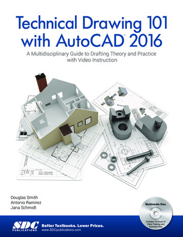
Dynamic Blocks in AutoCAD: Part 3Naming Parameters and ActionsParameters have a label that appears when you edit the block in the Block Editor. Bydefault, the label is generic, and if you create more than one of the same parameter, theyare numbered consecutively. For example, if you create two linear parameters, they arelabeled Distance and Distance1. To help make your labels more meaningful, you can, andprobably should, change them. If your linear parameter measures the width of a door, youcould change the label to Door Width.To change a parameter label, use the Label option at the first parameter prompt when youcreate the parameter. Or, you can create the parameter with the default label, select theparameter, and change the label in the Properties palette.Note that parameters also have a name, which doesn’t appear in the Block Editor andsimply denotes the type of parameter. For example, if you create a linear parameter, itsname is Linear. If you create a second linear parameter, its name is Linear1. Although youcan change a parameter name in the Properties palette, it’s probably best not to do so,because these names can help you understand the type of parameter you’ve used whencreating the Dynamic Block.Figure 1: Aparameter hasboth a name anda label.Actions have names only (no labels), and you may want to change these to make themmore meaningful. If you create more than one of the same action type, they are alsonumbered consecutively (for example, Stretch and Stretch1) as needed. If your stretchaction changes the width of the door, you could change the action name to Stretch Door.Figure 2: The linearparameter’s label isDoor Width. Twoactions are namedStretch Door andScale Door Swing.www.autodesk.com/autocad-blocks2
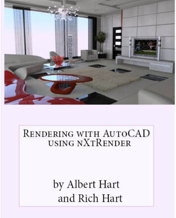
Dynamic Blocks in AutoCAD: Part 3Actions also have a type (such as Stretch). The action type appears in the Propertiespalette, but you can’t change it.Selecting Objects for ActionsWhen you add an action to a parameter, you must select objects to create a selection setfor the action. Often, you want to select not only drawing geometry, but the parameter aswell. In fact, sometimes, you need to select other parameters on other objects to get theresults you want.For example, let’s say that you have a desk with a linear parameter and a stretch actionso that you can stretch the width of the desk. You want to be able to move the chairindependently (so it has a point parameter and a move action), but you also want it tomove to the right when you stretch the desk to the right. To accomplish this, when youselect objects for the desk’s stretch action, you need to include the chair and its pointparameter. Therefore, you need to create the parameter for the chair before you createthe stretch action for the desk. In general, if you want to include another object in anaction that has a parameter of its own, you should create the two parameters first, beforeadding the first action.Figure 3: Createdifferent results bychanging the selectionset for the desk’sstretch action.www.autodesk.com/autocad-blocks3
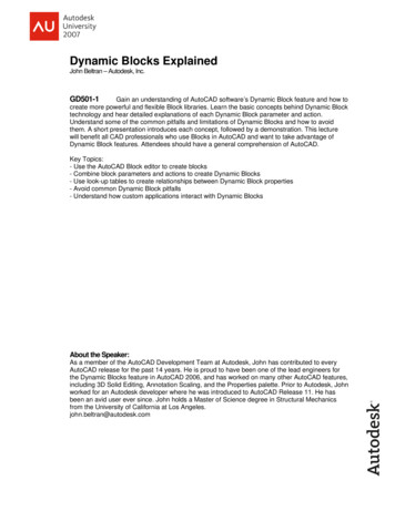
Dynamic Blocks in AutoCAD: Part 3A common use for including a second parameter in the selection set of an action is for abase parameter. Use a base parameter if you want the base point of the block referenceto remain in the same position relative to the block, for example, at the lower-left corner ofa rectangle, even when that position moves. If an action (such as stretch or move) movesthat lower-left corner, then you should include the base parameter in the selection set ofthat action, along with its parameter. Then the base point of the block always remains inits proper location when you edit the block in a drawing.Specifying Stretch FramesStretch actions require you to specify a stretch frame before selecting objects. Thepurpose of the stretch frame is not always obvious at first. This stretch frame specifies thatpart of geometry that is included in the action. You can specify it with a selection orcrossing window. Then you can select objects with a crossing window or by picking theobjects. Often these two windows are similar (although they need to use slightly differentpoints). The following example shows the result of two different stretch frames whilestretching a rectangle in a drawing. In Figure 5, the stretch frame includes only the upperright corner of a rectangle, so only that corner stretches. In Figure 6, the stretch frameincludes the entire right side so the entire side stretches.Figure 5: Upper-rightcorner included instretch frameFigure 6: Entire rightside of rectangleincluded in stretchframe.www.autodesk.com/autocad-blocks4
Dynamic Blocks in AutoCAD: Part 3Cycling Through Insertion PointsIf your block has several actions, or alignment or base point parameters (which require noaction), the block has several grips. You can cycle through these grips when you insert theDynamic Block by pressing the Ctrl key.Figure 7: Pressing theCtrl key while insertingthe block moves theinsertion point fromgrip to grip, althoughthe cursor positiondoes not change.By default, insertion cycling is on. You can turn it off for any grip by selecting just the gripand changing the Cycling property in the Properties palette to No. You can also use theBCYCLEORDER command in the Block Editor to change the cycling order of the grips inthe Insertion Cycling Order dialog box.Changing the Direction of an ActionFor move, stretch, and polar stretch actions, you can change the direction of an actionrelative to its parameter. For example, you may want to drag to the right but make anobject stretch vertically at a 90-degree angle. This is called an angle offset. A commonuse is a door block that you stretch to the right to change the width of the door opening.The door itself should vertically stretch the same amount, and the arc swing should scaleat the same time. Note that if you just scaled the entire door, the door itself would getthicker as you widened the door opening—a result that you don’t want.Figure 8: Left, door inBlock Editor. Right,editing the door in adrawing.www.autodesk.com/autocad-blocks5
Dynamic Blocks in AutoCAD: Part 3To create this angle offset, you author the Dynamic Block shown in the figure as follows:1.Create the door by drawing a rectangle and an arc. Make a block from these objects,and use the lower-left corner of the door as the base point.2.Open the Block Editor, and select the door to edit.3.Create a linear parameter as shown on the left side of the figure, to represent thedoor width. Select the parameter, right-click it, and choose Grip Display 1 to showonly a grip on the right end of the parameter.4.Add a stretch action to the linear parameter. For the stretch frame, specify a windowthat covers the top part of the rectangle. When you select objects, select everythingexcept the arc.5.Select the stretch action. In the Properties palette, change its Angle Offset value to90.6.Add a scale action to the linear parameter, and select the arc.7.Save the block and close the Block Editor. When you grip-edit the block, click thestretch grip to change the door opening. The door stretches in the 90-degree directionand the arc scales correspondingly.You can also create the angle offset while creating the action. At the Specify ActionLocation or [Multiplier/Offset] prompt, use the Offset option and set its value to 90.Keeping Objects CenteredMany blocks have centered components that need to remain centered as you stretch theentire block. For example, the valve part in the following figure may come in severaldiameters, but the hole must always be centered.Figure 9: This valvepart’s central holeneeds to remaincentered regardless ofthe diameter of theentire part.To keep a component centered, you use a distance multiplier of 0.5, so that thecomponent always moves half the distance of the rest of the block. In this example, youcan use a stretch action to change the diameter (a linear parameter) of the entire block.The two vertical lines in the middle (the central hole) have a move action attached to thesame linear parameter, with a distance multiplier of 0.5.To create a distance multiplier, you add an action as usual. After the prompt to selectobjects, you see the Specify Action Location or [Multiplier/Offset] prompt. Use theMultiplier option to specify the distance multiplier. You can also change the multiplierafterward by selecting the action and using the Properties palette.www.autodesk.com/autocad-blocks6
Dynamic Blocks in AutoCAD: Part 3Stretching a Block Equally in Opposite DirectionsAnother way of handling the previous example would be to stretch the two sides and leavethe middle alone. Some blocks always need to remain symmetrical, so if you stretch oneside, the other side needs to stretch an equal amount.Figure 10: An I-beamin the Block Editor.The I-beam has a linear parameter and two stretch actions, both attached to the same grippoint on the right side of the parameter. Because you don’t need the grip on the left, selectthe parameter, right-click it, and choose Grip Display 1. The Stretch Left action’s angleoffset is 180 degrees. A base point parameter at the upper-left corner, which is included inthe selection set of the Stretch Left action, keeps the base point at that corner, even whenthat corner moves in the stretching action. As you drag the rectangular grip in a drawing,both sides of the I-beam stretch by the same amount.Figure 11: Stretchingthe I-beam in adrawing.www.autodesk.com/autocad-blocks7
Dynamic Blocks in AutoCAD: Part 3Chaining ParametersSometimes, you need one action to cause another action to occur. If those two actionscan share a parameter grip, then you can accomplish this easily. For example, the doorshown in “Changing the Direction of an Action” earlier in this document has two actions: ascale action that scales the arc and a stretch action that stretches the door. Becausethese two actions can share one parameter and grip, when you stretch the door, you alsoscale the arc.However, sometimes your geometry is more complex and you need more than oneparameter. Yet you still want one action to activate another action. You do this using thechaining feature. Because you want one action to activate another one, you need twoactions and two parameters. The principles of chaining are as follows: Parameter 1 has an action, whose selection set includes parameter 2, in additionto any other objects it needs to function. (Note: If the action is a stretch action,the stretch frame also needs to include parameter 2.)Parameter 2 has an action; parameter 2’s chaining property is set to Yes.When you grip-edit the block using the action of parameter 1, the action of parameter 2 isactivated at the same time.You need to set up chaining in a logical order:1.Decide which action you want to grip-edit. This is the action that will activate anotheraction. You can call it the main action.2.Decide on the parameters you need and their actions.3.Create the parameters first.4.Create the main action and attach it to its parameter (parameter 1).5.When you specify the main action’s selection set, be sure to include the parameter ofthe second action. (Don’t include the objects that are in the selection set of thesecond action.)6.Create the action for parameter 2.7.Set the chaining property of parameter 2 to Yes.Tip: Because parameter 2’s action is automatically activated, it doesn’t need any grips. Toavoid confusion during editing, you can remove all its grips. Select it, right-click it, andchoose Grip Display 0.www.autodesk.com/autocad-blocks8
Dynamic Blocks in AutoCAD: Part 3In the following example, you want to stretch the cut-out sheet metal plate and create anarray from the small circle (the cutout) at the same time. You want the circles to have 0.5units between them, and you also want to maintain equal spacing at either end ofthe plate.Figure 12: A cut-outsheet metal plate. (Thedimensions aren’t partof the block.)Figure 13: The block inthe Block Editor.The stretch action is the main action that you want to be able to grip-edit. As you stretch tolengthen the plate, you want the circle to create an array. Here’s how to set up this block:1.Create the block, and open it in the Block Editor.2.Add a linear parameter (parameter 1), called Straight Length, along the straight partof the object. (The plate is a polyline.) In the example, this parameter is 2 units longand has an increment value set with an increment of 2.5, a minimum of 2, and amaximum of 20. Set the grip display to 1.3.Add a second linear parameter (parameter 2), called Array Length. This parameter is2.5 units long.4.Create the stretch action for the Straight Length parameter. When you specify thestretch frame, include the entire Array Length parameter. When you select objects,again include the Array Length parameter, but not the circle. (Because the ArrayLength parameter is inside the circle, if you use a crossing window, you need toinclude the circle in the crossing window and then use the Remove option to deselectthe circle. Another method is to just select the Array Length parameter.) Set the gripdisplay to 0 and the Chain Actions property to Yes.5.Create the array action for the Array Length parameter. In the example, the columnoffset is 2.5 units.6.Save the block, and close the Block Editor.www.autodesk.com/autocad-blocks9
Dynamic Blocks in AutoCAD: Part 3When you grip-edit the block in the drawing, you see only one grip, so you don’t have toremember which grip to stretch.Figure 14: Stretchingthe block in thedrawing also createsan array from thecircle.As you drag parameter 1 a specific distance and angle, parameter 2 moves the samedistance and angle. For this reason, chaining is useful when you want to maintain aconstant relationship between two components in a block. In the example, the relationshipbetween the circles and the ends of the plate stays the same, so that the circles arealways centered inside the plate.Figure 15: The block isnow stretched and thecircles are arrayed.Using Visibility StatesA visibility parameter turns the visibility of a block component on and off. The visibilityparameter doesn’t take an action. A Dynamic Block can have only one visibility parameter.You define visibility states, each of which is a variation of visibility or invisibility. You canmake one or more components visible or invisible. In the following figure, all the resistorvariations are one Dynamic Block. The components that are different are specified asvisible or invisible for each of five visibility states. You’ve just combined five blocks intoone!Figure 16: Fixed value,variable, adjustable,temperature variable,and photo resistors—visibility variations ofone block.www.autodesk.com/autocad-blocks10
Dynamic Blocks in AutoCAD: Part 3You can use visibility states to switch among objects. For example, you might want tohave two variations of a telephone on a desk—a single-line phone and a multiline phone.By putting these two phones in the same location and setting two visibility states, you canchoose which phone to display when you edit the block.Figure 17: These twophones are in thesame location in theblock, one on top ofthe other. You canchoose which todisplay using thevisibility parameterTo add a visibility parameter, follow these steps:1.Create a block that contains all the components that you need for all the visibilitystates.2.In the Block Editor, choose Visibility Parameter from the Parameters tab of the BlockAuthoring palettes, and place it near the items you want to make visible or invisible.3.Choose Manage Visibility States from the Block Editor toolbar (or double-click thevisibility parameter) to open the Visibility States dialog box.Figure 18: TheVisibility States dialogbox, after enteringsome visibility states.4.Click the default visibility state, called VisibilityState0. Type the name of your firstvisibility state, and press Enter.5.Click New to open the New Visibility State dialog box. Enter the second visibility statename, and click OK. Repeat for all the visibility states that you want to create.6.Click OK to close the Visibility States dialog box. (The visibility state at the top of thelist will be the default state when you insert the block. You can choose a visibility stateand use the Move Up button to move it to the top of the list.)7.Choose the first visibility state from the Visibility States drop-down list at the right sideof the Block Editor toolbar. Select all the components that you want to be invisible forthat state. Click the Make Invisible button on the Block Editor toolbar.8.Repeat the previous step for each state. You can also select objects and make themvisible by clicking the Make Visible button. If you need to select an object that isinvisible, click the Visibility Mode button, which displays invisible objects in gray soyou can see and select them.www.autodesk.com/autocad-blocks11
Dynamic Blocks in AutoCAD: Part 3When you’re done, select each state from the drop-down list and check that it displays thecorrect objects. Save the block, and close the Block Editor.When you select the Dynamic Block in the drawing, click the down arrow to display the listof visibility states. Select a state to display it.Figure 19: Choosing avisibility state in adrawing.Visibility states are a powerful, yet simple way to add great flexibility to a block.Using Lookup Parameters and TablesA lookup parameter pairs with a lookup action to create a table that matches labels withvalues. Lookup tables are great when you want preset sizes for a block. For example, youmight have a part that comes in three sizes. When you insert and grip-edit the block, youjust choose a size from a drop-down list.Figure 20: Choosing adesk length from alookup table.The lookup parameter and action are based on another parameter and action, such as alinear parameter and stretch action. You may want to create a value set to preset thevalues that you can use in the lookup table, but you can also set the values when youcreate the lookup table.Here’s how to create a lookup parameter and action:1.In the Block Editor, add the parameter and action that you want to use as thebasis for the lookup parameter and action. The preceding example uses a linearparameter and a stretch action. If you add a value set (list or increment), themeasurements are available when you create the lookup table.2.From the Parameters tab of the Block Authoring palettes, add a lookupparameter.3.From the Actions tab, add a lookup action. The Property Lookup Table dialog boxopens.4.Click the Add Properties button, choose the parameter you want to work with,and click OK. You’re back in the Property Lookup Table dialog box.www.autodesk.com/autocad-blocks12
Dynamic Blocks in AutoCAD: Part 3Figure 21: Thecompleted PropertyLookup Table dialogbox.5.If you have values from a value set, click the first row of the Input Properties sideand click the drop-down arrow that appears. Choose the first value. Otherwise,just enter values on each row. Click the corresponding row on the LookupProperties side, and enter the label that you want for that value.6.Click the lower-right cell in the dialog box, which says Read Only by default.Choose Allow Reverse Lookup. For this to work, all rows in the table must beunique. Use this option in order to choose a value from a drop-down list whenyou insert the block.7.Click OK.8.Save the block, and close the Block Editor.Now, when you grip-edit the block, you’ll see a down arrow. Click the arrow to choose oneof the labels and apply its corresponding value to the block.Tip: You can extract parameter values like attributes. For example, if you choose a desklength of 7 feet, you can extract that value. You can also create invisible values that youcan extract using a lookup table. To do so, add a lookup parameter and action. Changethe label of the parameter to the property (like an attribute tag) that you want. Forexample, you could label the parameter “Chair Color.” In the Property Lookup Table dialogbox, add the colors on the Lookup Properties side, leaving the Input Properties side blank.In the drawing, you can choose a chair color by clicking the lookup parameter’s downarrow. You don’t see any change in your drawing, but when you extract attributes, thecolor appears in the output.www.autodesk.com/autocad-blocks13
Dynamic Blocks in AutoCAD: Part 3ConclusionDynamic Blocks in AutoCAD 2006 software give you more control over your blocks,helping you increase efficiency and get the job done faster. Dynamic Blocks enable you toreduce the size of your block libraries while giving you more block options that are easierto access, manipulate, and place. The advanced features detailed in this white paper helpto ensure that when you create blocks, you can place and manipulate correctly the firsttime—and be more efficient every time.Autodesk and AutoCAD are registered trademarks of Autodesk, Inc., in the USA and othercountries. All other brand names, product names, or trademarks belong to their respectiveholders. Autodesk reserves the right to alter product offerings and specifications at any timewithout notice, and is not responsible for typographical or graphical errors that may appear inthis document. 2005 Autodesk, Inc. All rights reserved.www.autodesk.com/autocad-blocksAbout the AuthorEllen Finkelstein has beenusing AutoCAD since 1986.She is author of AutoCAD2006 and AutoCAD 2006 LTBible.14
AutoCAD 2006 1 Dynamic Blocks in AutoCAD Part 3 of 3: Advanced Features of Dynamic Blocks. This is the third of three white papers on Dynamic Blocks in AutoCAD 2006 software. This white paper introduces some of the special techniques and advanced