Transcription
ArchitecturalConcrete3 PDH / 3 CE Hours / 3 AIA LU/HSWDepartment of the ArmyU.S. Amy Corps of EngineersPDH AcademyPO Box 449Pewaukee, WI -9098
Architectural Concrete Final Exam1. Regarding Crack control (cast-in-place), dueto , stresses are produced instructural concrete where restraint occurs andcracks may develop.a. sub-zero temperaturesb. natural drying shrinkage of concretec. uneven loadingd. heat2. Considering Materials and economics, selectionof forms for architectural concrete is not onlydetermined by the desired but by thenumber of expected reuses, form installation,form removal, and use of form ties.a. textureb. strengthc. colord. thickness3. The architect’s selection of the pattern ortexture may determine the type of:a. concreteb. plasticizersc. colorantd. form material4. With respect to Concrete Material andProportions, the used for architecturalconcrete must come from the same source forthe duration of the project to prevent majorchanges in color.a. aggregateb. cementc. plasticizersd. form release agent5. For Concrete Placement, most specificationsrequire layers to be held to heights lessthan:a. 0.2 m (8 in.)b. 0.4 m (16 in.)c. 0.6 m (24 in.)d. 0.8 m (32 in.)ARCHITECTURE6. Exposure of aggregate by is thegeneral method of exposing aggregate in precastand cast-in-place flatwork.a. acid etchingb. sand blastingc. wire brushingd. water brushing7. Bush hammering by fracturing thesurface of the concrete through impact of apneumatically driven tool with steel teeth.a. crushes the aggregateb. exposes the aggregatec. removes imperfectionsd. alters the color8. The fractured rib texture requires:a. crushed aggregateb. metal formsc. an as-cast ribbed finish initiallyd. adding colorant to the release agent9. With regards to Protective Coatings, manycoatings are and should be tested onthe field mockup for yellowing, chalking, andeffect on concrete color and texture.a. acidicb. abrasivec. proprietaryd. generic10. The architectural treatment of concrete maybecome an important issue when the structureis located:a. in the southwest United Statesb. in a populated area or in a tourist sitec. in an industrial settingd. within a TIF district 3
Architectural ConcreteAIA CES Course Number: AIAPDH133Course Description:This course provides guidance for the design and construction of architectural concrete, includingplanning and design, forms, materials and proportions, batching and transporting, placement,curing and form removal, exposed aggregate surfaces, finishing, and quality assurance. Coursematerial is from the U.S. Army Corps of Engineers, Manual 1110-1-2009.Learning Units:3.0 LU/HSWLearning Objective 1:Upon completion of this course, the student will understand the structural design parametersthat are essential in architectural concrete construction and that must be addressed by thedesigner.Learning Objective 2:The student will learn many of the techniques used to obtain various finishes and appearances aswell as how to specify them.Learning Objective 3:The student will understand specific material batching and concrete placement techniques andhow these affect the final appearance.Learning Objective 4:The student will know how defects should be repaired and will be aware of final finishingtechniques.EM 1110-1-2009DEPARTMENT OF THE ARMYU.S. Army Corps of EngineersWashington, DC 20314-1000Manual No. 1110-1-2009 31 October 1997Engineering and DesignARCHITECTURAL CONCRETEARCHITECTUREArchitectural Concrete 85
CHAPTER 1 – GENERALCHAPTER 2 –PLANNING AND DESIGN CRITERIA1-1. Purpose and ScopeThis manual provides guidance for the design andconstruction of architectural concrete, includingplanning and design, forms, materials and proportions,batching and transporting, placement, curing and formremoval, exposed aggregate surfaces, finishing, andquality assurance.1-2. ApplicabilityThis manual applies to all HQUSACE elements and allfield operating activities (FOA) having civil works and/or military programs responsibility.1-3. ReferencesReferences cited in this manual are listed in AppendixA.1-4. Distribution StatementApproved for public release, distribution is unlimited.1-5. Definition-Architectural ConcreteThe American Concrete Institute (ACI) definesarchitectural concrete as concrete exposed as aninterior or exterior surface in the completed structure.1-6. SpecificationsSpecifications can be performance type, where thequality of the end product is specified or prescriptiontype, where methods, materials, and procedures arespecified. The performance type requires the contractorto be entirely responsible for the quality of the endproduct. The prescription type requires acceptanceof the completed product if the contractor hasfollowed the specifications. An architectural concretespecification is usually a combination of both.1-7. DrawingsArchitectural concrete contributes to the visualcharacter of the structure and must be designated assuch in the contract drawings and specifications. Allsurfaces to have an architectural concrete appearancemust be labeled on the contract drawings in order toprevent controversy during construction. This includeslimits, location, and type of treatment.86 Architectural Concrete2-1. Structural GuidelinesThis chapter delineates structural design parametersthat are essential in architectural concrete constructionand must be addressed by the designer. Theseparameters emphasize the need for designs that are inexcess of those for structural concrete construction.a. Crack control (cast-in-place). Due to natural dryingshrinkage of concrete, stresses are produced instructural concrete where restraint occurs and cracksmay develop. In as-cast finishes, cracks are of minorimportance when sufficient reinforcement is used tohold them to fine widths. Surfaces to be sandblastedfor treatment cannot tolerate any cracking, as thesandblasting tends to widen very fine cracks oraccentuate discernible cracks. To minimize visiblecracking, sufficiently deep rustication joints canbe placed at regular intervals to draw the crackingwhere sealants can be used to seal against leakingand conceal the cracking. Placement of concretecan be limited by section in long walls to allow forthe anticipated volume changes. The recommendedmaximum spacing of vertical construction jointsfor a wall placement is 60 ft and the recommendedvertical contraction joint spacing is as follows:Wall heightVertical contraction joint spacing0.6-2.4 m (2-8 ft)3 times wall height2.4-3.7 m (8-12 ft)2 times wall height 3.7 m (12 ft)1 time wall heightb. Crack control-(precast). Precast architectural unitsshould have some flexibility after erection to allowfor distortions due to temperature and shrinkageand movements of the building’s structural framewithout cracking.c. Deflections. Architectural concrete requires more rigidcontrol of deflections for long span smooth concretegirders to prevent an appearance known as “opticalsag.” As limitations are determined by personalpreference, deflections should be minimized byovercorrection of the camber needed to offset thetotal deflection. Total deflection is the sum of allindividual computed deflections due to all loadingsplus those due to time-dependent effects. Specificinformation is given in ACI 435R-95 (ACI 1995b).d. Reinforcement. Sufficient reinforcement is requiredat window corners and other openings to preventthe formation of cracking. Horizontal steel in wallsshould be increased 50 percent above the ACI318 (ACI 1995a) minimum requirements. Whererustication is used or aggregate is to be exposed onARCHITECTURE
the surface, remaining cover should be sufficient toprotect the reinforcement against the environment.If the cover is minimal, reinforcement can beprotected by an epoxy coating, or the use of stainlessor galvanized steel. The amount of horizontalreinforcement crossing a planned crack control jointshould not exceed 50 percent of the normal wallreinforcement.e. Reinforcement chairs and spreaders. Plastic chairsor spreaders are best for the architectural face toavoid rusting. In girders having large amounts ofhorizontal reinforcement, chairs must be sufficientto prevent compression of the soffit wood formand possible exposure of the chair legs after formremoval. Investigation is needed to determine theeffect or exposure of chairs by surface treatmentssuch as sandblasting or bush hammering. Forinformation on the use of plastic-coated chairs,attention is directed to ACI 315 SP-66.2-2. Architectural GuidelinesInnumerable choices of patterns, finishes, color oxides,aggregate colors, and cements are available to thearchitectural designer to achieve a desired effect. Oncethe desired combination is achieved, responsibility forobtaining the architectural product is shared by thecontractor and the contracting officer. In order to judgeacceptability, general guidelines contained in ACI303R state that acceptable architectural surfaces shouldhave a pleasing appearance with minimal color andtexture variations, and minimal surface defects whenviewed from a distance of 6.6 m (20 ft). For surfacessuch as stairwells having close contact with thepublic, specifications should contain more stringentrequirements.a. Finishes and patterns. Architectural concrete surfacescan be as-cast, where the mortar surface appearanceis determined from the type of forming used tomold the concrete and the end result is smoothor patterned. Surfaces can also be textured byremoval of the mortar surface in order to exposethe aggregate. This technique may remove all of thepattern due to forming. Either method can be usedto break up the large, smooth, open, and flat surfaceswhich accentuate all variations from a plane surfacein the forming. For specific information, attention isdirected to ACI 1974.b. Colored concrete. The color of architectural concretecan be varied with the use of color oxides, colorand brand of cement, or stains. As acceptance isusually determined by individual preference, mostpublications do not contain detailed criteria forjudgement. Generally, colored architectural concretehaving minor color differences but exhibitingexcellent uniformity on separate building elevationsor elements, will be acceptable. Precast panels arevulnerable to such judgement upon erection andARCHITECTUREmust be manufactured with materials chosen fortheir uniformity and using personnel and methodsknown to produce uniform coloration. A goodquality control program will check color and textureuniformity in the plant prior to shipment. Colorvariations for field cast-in-place concrete can beheld to a minimum by maintaining uniformityin materials, concrete production, delivery, andplacement, construction procedures, curing andfinishing.c. Rustication and joints. The use of rustication andjoints will simplify and ease the construction ofarchitectural concrete surfaces as it allows theplanning of efficient placement of the concrete andstill achieves a pleasing result. Patterns of rusticationand joints can be used to break up large flat areas,isolate placements to eliminate any possible leakagetraces, cover form joints and control shrinkagecracking to desired locations.(1) Chamfer strips. Chamfer strips are recommendedfor internal form corners to aid in form removalwithout damage to the concrete. Wood chamfersshould have a minimum face width of 1 in., thesame texture as the adjacent form, be sealed toprevent absorption, and edge-sealed to preventleakage behind the chamfer. Acute and rightangle corner details are possible but requirespecial form details to allow easy form removalwithout damage to the corners.(2) Wood rustication strips. Recommendeddimensions and details for wood rustication stripsare as follows:(a) Depth of 19 mm (3/4 in.) for small rusticationgrooves.(b) Depth of 37.5 mm (1-1/2 in.) for crack controljoints and panel lines.(c) Widths equal to depth for wooden strips.(d) Minimum draft (angle or taper in side) of 15deg for form removal.(e) Uniform cross section and strength for goodalignment.(f) Other types of strips. Strips made of metal orsimilar stiffness should be 19 mm (3/4 in.) inwidth or wider. Extreme care is needed duringfastening and sealing of openings.d. Drainage. To prevent staining, drainage water mustbe restricted from running down the face of thearchitectural concrete by designing drip molds atsoffit edges of all angular and horizontal offsets. Thedrip molds should be a minimum distance of 25 mm(1 in.) from the face of the concrete or a distanceequal to the maximum size of the aggregate. Toassist self-washing of air pollutants deposited onthe architectural surfaces and openings, downwardArchitectural Concrete 87
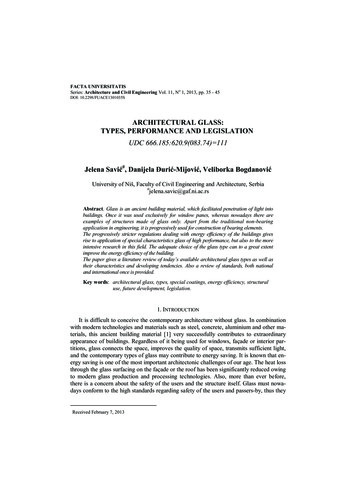
slopes should be provided on sills and top surfaces ofprojecting details. Upward slopes should be providedfor the upper surfaces of recesses. Such slopes canbe 1:12 for smooth surfaces to 1:1 for textures.Rainwater should be directed away from thearchitectural face on the upper surfaces of parapets.2-3. Design Reference Sample and MockupsIn order to properly specify and construct anarchitectural concrete structure, use of the designreference sample and mockup can lead to properdecisions during the bidding and construction stages.For some projects, the mockup may become an interiorwall which is to be eventually covered. All projectsincorporating architectural concrete should havean acceptable sample mockup constructed by thecontractor’s forces for control purposes. Architecturalspecifications should state that no architecturalproduction forming will be constructed until acompleted mockup has been approved.has the capability of producing the specifiedarchitectural concrete, a job-site mockup should berequired by the contract specifications. A satisfactoryjob-site mockup is illustrated in Figure 2-2. Forlarge major projects, a separate contract may belet to construct a special full-scale mockup usingthe proposed
attention is directed to ACI 315 SP-66. 2-2. Architectural Guidelines Innumerable choices of patterns, finishes, color oxides, aggregate colors, and cements are available to the architectural designer to achieve a desired effect. Once the desired combination is achieved, responsibility for obtaining the architectural product is shared by the contractor and the contracting officer. In order to .