Transcription
Service DepartmentHAPPY Voyager HCS-1201Procedures For Maintenance/Technical PersonnelHAPPY HCS-1201HCS 1201 OOperationsti&MMaintenancei tFor Maintenance/Technical PersonnelUpdated Nov 2, 2011 written for Firmware Version 1.16This guide is intended to provide convenient, clearly-written and illustrated instructions for procedures thatmaintenancei tpersonnell are requiredi d tto kknow ffor servicingi i HAPPY HCSHCS-12011201 Voyager.VIt doesdnott replacelthethfactory-developed maintenance manual, which remains as the principal technical reference for this machine.Electronic Updates / Procedures Removing Voyager’s outer coversStarting the machine in Maintenance ModeFirmware Update – (by CF Card/Jump Drive)Firmware Update – (by CN-ROM chip)Needle Memory resetSpeed and System resetMemory Re-initialization from Maintenance Mode245799Mechanical Procedures / Replacements Rotary hook timing Hook retainer adjustment Presser foot height inspection and adjustment Needle Depth inspection/ Depth Gauge / Knowledgeg Knife – about, timingg and adjustmentj Moving Knife Base: Exchange / Knowledge Needle bar boss / fixing boss jamsOther Error Code List (Updated as of Nov 2011)Chapter 4: Troubleshooting & Maintenance101314162024252611
Service DepartmentHAPPY Voyager HCS-1201Procedures For Maintenance/Technical PersonnelRemoving Voyager’s Outer CoversFor some of the procedures in this guide, it may be necessary to remove Voyager’s outer covers.Remove the left-side cover first. (side without control panel). This can be done without removing the other side.Some repairs including moving knife timing can be made by removing only this side cover.1. Remove the thread stand and base. Then the bobbin winder. First,remove the bobbin winder tension knobknob. ThenThen, insert a flat-tipscrewdriverflat tipscrewdriver intothe slot on the tension knob shaft to and loosen before removing.2. Next, remove these 2 screws(indicated by the red arrows)3. Separate thelockingoc g tabsjoining the left andright side coversat theselocations.Chapter 4: Troubleshooting & Maintenance22
HAPPY Voyager HCS-1201Procedures For Maintenance/Technical PersonnelService DepartmentRemoving Voyager’s Outer Covers(Continued)Remove the right-side cover. (side with control panel). Note: This cover can be freed enough without removing the controlpanel to allow some common repairs: CPU board re-set/replace; serial/usb circuit board. Needle change cam repairs,presser foot motor.1 Di1.Disconnectt ddatat cablebl shown.h2. Disassembleand removeLCD panel fromarm. (Detailedprocedure notshown in thisguideguide.4. Remove screw shown.5. Remove 3 internal screws shown here.Chapter 4: Troubleshooting & Maintenance3. Removemanual colorchange knobwith 1.5mm hexwrench.6. Disconnect cable at rear forUSB/serial LAN ports.33
HAPPY Voyager HCS-1201Procedures For Maintenance/Technical PersonnelService DepartmentElectronic Updatespthroughg Maintenance ModeKey electronic adjustments can be made on Voyager through Maintenance Mode. Refer back to the procedure on this pagefor other key procedures later on in this guide.Entering Maintenance ModeFollow these steps:1.Power off the machine.2.Press and hold the MENU key while powering the machine back on.3.The normal startup screen appears. Press the SET key to continue as normal.4.Navigate to the OTHER sub-menu. A newCalendaroption will appear as shown on the right:Network5.Choose Maintenance and pressSystemSET.SpeedVersion6.Enter code 2251 using the 4 arrow keysMaintenanceMaintenanceand press SET.[Maintenance]Input Code22517.The Maintenance Screen appears, from which you can perform different electronic adjustments.[Maintenance]Machine: AAngle:0Memory:Display: Install:Record:Chapter 4: Troubleshooting & Maintenance44
HAPPY Voyager HCS-1201Procedures For Maintenance/Technical PersonnelService DepartmentElectronic Updates:pFirmware UpdatespHAPPY provides updates to Voyager’s on-board firmware for functional improvements and occasional bug fixes. Thefirmware can be updated either through a CompactFlash card, Jump Drive, or in cases when the machine cannot be restarted, by flashing from a CNROM chip on the internal CPU board. The firmware updates are divided into the followingsections: (1) LCD Control program; (2) Language; (3) CPU board control program and (4) on-board letteringFirmware Update via CF Card or Jump DriveThis method is the most convenient, requiring no machine disassembly. For the update, the correct update files for theabove 4 must be saved onto the ROOT DIRECTORY of a compatible CF card or USB jump drive (if the machinehas a USB jump drive port). There are 2 files for each section – a .bin file (the actual data) and a .upi file (updaterfile). A complete set of update files might look like this below:LCD Controller update files:Language update files:CPU board control updates:On-board lettering updates:LCDHA103.binLCDHA103.upiH eng160.binH .upiVersion numbers may vary for different updates. The file versions listed above are correct for firmware version1 16 which is current as of November 2011 for color monitor versions of Voyager1.16,Voyager.Procedure1.Save the above files onto a CF card or USB Jump Drive (on the drive’s root directory) and insert the cardor drive into the machine.2.Start the machine in maintenance mode (as described on the previous page)Chapter 4: Troubleshooting & Maintenance55
HAPPY Voyager HCS-1201Procedures For Maintenance/Technical PersonnelService DepartmentElectronic Updates:pFirmware UpdatespFirmware Update via CF Card or Jump Drive (continued)3. Update the Language File first. From the Maintenance screen, choose Install, then Install from thesub-menu. Then, choose the update file for language. The language file name will start with the letters “Eng” forEnglish, “Spa”Spa for Spanish, etc.[Maintenance]Machine: AAngle:0Memory:Display: Install:Record:[Maintenance][ Install Mode ] 1: eng170- - Installing Data - -Install:prog:pgletterfont:Note that only 1 file shows (the bin file) for each stage. After pressing SET ,the message “installing data” appears. Wait until the update is complete and letmachine rere-bootboot automatically,automatically prompting you to press SET to return to the mainDrive screen. Before continuing to the next stage, be sure to shut down againand re-boot into Maintenance mode.Auto re-boot4. Update the ATA Board Controller Program. This step is similar to the language program update – from theMaintenance screen, choose Install, then Install again.gChoose the file with the name startingg with “LCDHA”,as shown here. Again, wait until the process completes – the machine will re-boot again, and you’ll have to shutdown again and re-start in Maintenance mode to continue to the next stage.[Maintenance][ Install Mode ] 1: LCDHA103LCD Control Panel InstallingAuto re-bootChapter 4: Troubleshooting & Maintenance66
HAPPY Voyager HCS-1201Procedures For Maintenance/Technical PersonnelService DepartmentElectronic Updates:pFirmware UpdatespFirmware Update via CF Card or Jump Drive (continued)5. Update the CPU control program. From the Maintenance screen, choose Install, then Prog from thesub-menu. Then, choose the update file for the CPU, with the name starting with “CHCS”.[Maintenance]Machine: AAngle:0Memory:Display: Install:Record:[Maintenance]Choose“PROG” thistime![ Install Mode ]Install:prog:letterfont: 1: CHCS116Load 1.16- - - - - - - - CompleteOnce again, wait until the update process completes before continuing. Note: At this stage the process iscomplete. The on-board lettering program may be updated here, but as of this writing, updates to thisprogram have been frozen by HAPPYHAPPY.6. Verify updates. After re-booting, you can check firmware version: from the main screen, press MENU,navigate to Other, then select Version to confirm the new firmware version#.7. Re-Set the machine. Perform a standard re-set of the machine from the main menu – press MENU, thenchoosehOTHER anddddo ththe ffollowing:ll i- Select SYSTEM and press SET. This re-sets the on-board program instantaneously.- Select SPEED and press SET. This will re-set the firmware-to-inverter programming, running the machinegradually through its full speed range, then stop. Select OK at the warning “Caution: Main Shaft Turns”, toallow this to continue. The needle will not engage during this procedure, but the take-up lever will engage.Chapter 4: Troubleshooting & Maintenance77
HAPPY Voyager HCS-1201Procedures For Maintenance/Technical PersonnelService DepartmentElectronic Updates:pFirmware UpdatespFirmware Update via CN-ROM”Follow the procedures on this page to update Voyager’s firmwarevia CN-ROM.[Maintenance]Machine: AAngle:0 Memory:Di lDisplay:Install:Record:To clear1 Re1.Re-initializeinitialize machine memorymemory. This will erase all designsdesigns.memoryTo do this, boot into Maintenance mode, and chooseMemory. Follow the prompts to clear the memory.2. Power off the machine and open the control panel-sidecover to expose the CPU board. Find the ROM socket on the CPU.3. Insert the CNROM CHIP, oriented with the notch facing downwards.4 Set4.S t DIP switches,it hthenth power on. FindFi d theth DIP switchit h panell on theth llower-righti ht corner off theth CPU bboard,dand set DS4 to “ON” and DS2 to “OFF”. Then, power on the machine.ROM socketk on CPU bboarddROM chip inserted with notch facing downwards!DIP switch settings for firmware update5. Allow process to complete, then power down.6. Reset DIP switches back: DS4 should return to the “OFF” position and DS2 should be set to “ON”.7. Remove ROM chip8. Clear Memory as performed in step (1) above.9. Re-Set Needle Position (see next section).Chapter 4: Troubleshooting & Maintenance88
Service DepartmentHAPPY Voyager HCS-1201Procedures For Maintenance/Technical PersonnelElectronic Adjustments:jNeedle MemoryyIn cases where the machine loses “track “ of the correct needle position number (for example, control panel willshow needle 12 while the head is actually positioned over a different needle), follow this procedure to re-set theneedle memory of the color change potentiometer and cam.[Maintenance]1. Move machine manually to needle 1 with the manual knob. Machine: AChange to D,D E,E or F2 Boot into maintenance mode as described on page 22.2.Angle:0for steps 4-73. Choose “MACHINE” from the maintenance menu and pressMemory:Display:SET.Install:4. Select option “D” using the arrow keys, then press SET.Record:5. Move machine manually to needle 12 with the knob.6. Select option “E” using the arrow keys, then press SET.7 S7.Selectl t optionti“F” usingi ththe arrow kkeys, ththen press SETSET. ThisThi isi a testt t function.ftiMoveMtheth manuallneedle change knob to each needles. The screen should now display the proper needle number asit comes to rest over the needle plate. If it doesn’t, repeat the procedure.8. Press SET after checking, then choose “END” to exit the test mode.9. Restart the machine normally.Electronic Adjustments: Speed ResetIn some cases, the inverter may revert to a mode that does not allow full sewing speed, often limiting speed to 500 stitchesper minute. This can result from either a fault or during certain normal maintenance procedures such as firmwareupdates. In such cases, the control panel provides an on-board re-set in normal operation mode.1. Go to the main menu by pressing MENU from the main Drive screen. Go to the 2nd screen of options.2. Select OTHER and press SET.3. Choose SYSTEM and press SET. Continue on to re-set the on-board program. This happensinstantaneously and returns you to the boot screen.4. Return to the OTHER sub-menu as in steps 1 and 2 above.5 Choose SPEED from the menu and press SET A warning will appear “Caution:5.Caution: Main Shaft Turns!”Turns! .Press SET to continue. The main shaft will start to turn and accelerate slowly to full speed (needle willnot engage – only the take-up lever), then stop.Chapter 4: Troubleshooting & Maintenance99
Service DepartmentHAPPY Voyager HCS-1201Procedures For Maintenance/Technical PersonnelElectronic Adjustments:jMemoryy Re-InitializationMEMORYThe nature of storing electronic data sometimes creates opportunities for the machine to misinterpret the information itneeds to process. Stored designs can develop “glitches” that will affect the performance of the machine or cause it tomalfunction entirely. Re-initializing the memory can be a good resource for solving general machine malfunctions. Note:CPU Firmware Version 1.11 and later introduced improvements to make it easier to clear this memory.RE-INITIALIZING MACHINE MEMORYThere are 2 ways to do this, the simpler, more convenient way by booting the machine into a special maintenance modeand choosing the appropriate option to re-set memory. If, however, the control panel is completely inoperable, there is awaya to rere-setset the machine directlydirectl on the control panel circcircuitit boardboard, whichhich is ooutlinedtlined on the nenextt pagepage.Re-Initializing from “Maintenance” Mode1. Boot the machine into Maintenance mode. Do this by powering on the machine while pressing the MENU key.The machine will appear to start normally. On power-on, press SET to boot to the main (drive screen). Then, pressMENU to access the main menumenu, index to “OTHER” and press “SET”.“SET” Choose MAINTENANCEMAINTENANCE, then press SETSET.Enter access code 2251 and press SET. The machine is now in a diagnostic/maintenance mode.2. Re-set the machine memory. In the menu that appears, index to MEMORY and press SET. Follow the screenprompts afterwards to clear machine memory.2. Re-initialize machine settings according to the procedure on page 18.3. (Optional) Reset needle detection. This is sometimes necessary to after a memory re-initialization.Chapter 4: Troubleshooting & Maintenance10 10
Service DepartmentHAPPY Voyager HCS-1201Procedures For Maintenance/Technical PersonnelElectronic Updates:pMemoryy Re-InitializationRE-INITIALIZING MACHINE MEMORY (continued)Hardware-Re-Initialization of Machine Memory from the control panel circuit board1 Turn the machine off.1.off2. Remove the four screws on the control panel. Do this using a phillips screw driver. The screws are located neareach corner at the rear of the control panel.3 S3.Separatet theth monitor.itD thisDothi byb gentlytl leaningli theth monitorit away fromfth LCD boardtheb d andd rear off theth controlt l panel.lBe aware of the delicate wires that connect the two halves.4. Turn dip switch-1 down.5. Turn the machine on. Then press the Set button. The machine will display “Data Initialize”.6. Turn the machine off.7. Turn dip switch-1 up.8. Reassemble the monitor. Do this by reinstalling each of the four screws at the rear of the control panel.9. (Optional) Reset needle detection. It is sometimes necessary to reset the needle detection after a memory reinitialization (refer to page 16)Chapter 4: Troubleshooting & Maintenance11 11
HAPPY Voyager HCS-1201Procedures For Maintenance/Technical PersonnelService DepartmentMechanical Procedures: Rotaryy Hook TiminggThe precise timing wheel on Voyager (and other HAPPY machines) makes it possible for your customers to check hooktiming, allowing troubleshooting hook-related issues over the phone before visiting the customer site – the shortprocedure is outlined below. On the following page are the procedures for adjusting hook timing.Ch kiCheckingRRotarytHHookk TiTimingiandd ClClearanceIf you suspect that your rotary hook timing is off, you or your customer can check this easilyyourself following these steps:1. Power the machine on and allow it to continue to the main drive screen.2. Select needle six (6). Do this using thekeys on the control panel3. Remove the needle plate and bobbin case . Do this by loosening each of the two (2) flatheadscrews with an offset screwdriver (provided in the machine’s toolkit)3. Remove the bobbin case.Timing for HCS-1201is at 25 degrees.4. Engage the needle. Do this by pressing the P.FOOT key, which lowers thepresser foot. Then, grab the needle bar over the presser foot, and pull it downuntil it locks into place.5. Turn shaft to 25 degrees. Do this with a 3mm Allen wrench. Turn the main shaftfrom the rear of the machine clockwise to L 25 (25 degrees). The needle shouldbe down and in the basket area of the rotary hook at this point.With the needle engaged, it should fall intothis basket in front of the rotary hook andjust behind the retaining finger.Chapter 4: Troubleshooting & Maintenance12 12
HAPPY Voyager HCS-1201Procedures For Maintenance/Technical PersonnelService DepartmentMechanical Procedures: Hook TiminggChecking Rotary Hook Timing (continued)TIMING (left-right position) at 25 degrees:Viewing the hook assembly from the front of themachine, the point of the rotary hook shouldbe hidden behind the needle.HOOK-NEEDLE CLEARANCE (front-back) at 25 degrees:From the side of the machine, the point of the rotary hookppy 0.1-0.15mm from the back of theshould be approximatelyneedle (about the thickness of a business card). If the pointis either touching or too far from the needle, the machine isnot set correctly and will require adjustment.Note that the hook pointpasses behind the needleacross the lower portionof the scarf.This clearanceshould be aboutthe width of abusiness card.Chapter 4: Troubleshooting & Maintenance13 13
Service DepartmentHAPPY Voyager HCS-1201Procedures For Maintenance/Technical PersonnelMechanical Procedures: Hook TiminggAdjusting Rotary Hook Timing1. Loosen the Rotary Hook. Do this by loosening each of the three (3) set screwsthat attach the rotary hook to the rotary hook shaft. Start with the larger screw on themilled flat spot of the hook’shook s neck (lower right).right) Loosen screws just enough tobreak the hook loose on the shaft. Turn the wheel as necessary to access eachscrew from either side.(3/4 view) 3 set screws are locatedalong the rear “collar” of the rotaryhook.3. Reset the dial to 25 degrees. Check that the needle is lowered into the rotary hookbasket once more and that the main shaft dial is set 25 degrees. Adjust the mainshaft as necessary by hand at rear of the machinemachine.4. Move hook and tighten screws. Adjust the timing and clearance simultaneouslyaccording to the diagrams on the previous page. Tighten screws carefully. If necessary,have an assistant hold the main shaft exactly at 25 degrees while positioning andtightening.Helpful Hints- Have a helper hold the timing wheel at 25 degrees with the T-handle wrench asyou make your adjustments and tighten the screws.(side view) Turn the hook as necessaryfor easy access with a screwadriver.- Tighten each screw just enough to snug the hook back on the shaft, then re-checkre checkthe timing, then tighten each screw further. Tighten all screws as firmly as you canmanage. When practicing, re-check constantly as each screw is tightened.- Use a quality flat-tip screwdriver with a wide grip to help you apply enough torqueto secure the rotary hook tightly on the shaft.Loosenoose thiss scscrewewfirst before theother 2.Chapter 4: Troubleshooting & Maintenance14 14
HAPPY Voyager HCS-1201Procedures For Maintenance/Technical PersonnelService DepartmentMechanical Procedures: Hook Retainer AdjustmentjAbout the Hook Retainer (also called retaining finger)The hook retainer is located at the front of the rotary hook, near thetop of the bobbin case. It is responsible for keeping the inner basketand bobbin case from spinning freelyfreely, while still allowing thread topass across the front of the rotary hook.Stub of hookretainerAdjusting the Hook RetainerFollow this short procedure to adjust the hook retainer:Hook retainer orretaining finger1 Remove the needle plate.1.plate Do this by loosening each ofthe two (2) flathead screws with an offset screwdriver.2. Loosen the black screw. But do not remove. This will bethe small button head hex screw toward the right corner,facing downward.3. Move the retainer. Looking downward, set the stublocated at the center of the retainer to approximately0.8mm from the back edge of the rotary hook basket; orabout halfway into the basket. The photo on the lower rightshows a retaining finger close-upclose up with proper clearanceclearance.Location ofblack set screwPhoto of clearanceof retaining fingerstub from thenotch in the hook.4. Tighten Screw. And check that the inner basket of therotary hook does not rotate freely.Location ofblack set screwSide view, retaining fingerChapter 4: Troubleshooting & Maintenance15 15
Service DepartmentHAPPY Voyager HCS-1201Procedures For Maintenance/Technical PersonnelMechanical Procedures: Presser FootInspecting Presser Foot HeightFollow this procedure to check proper presser foot height:1. Engage the needle. Do this by pressing the P.FOOT key, which lowers the presser foot. Then, grab theneedle bar over the presser footfoot, and pull it down until it locks into placeplace.2. Turn the shaft to 0 degrees. Do this with using a 3mm hex wrench to turn the timing wheel at the rear ofthe machine.3 Ch3.Checkk ththe clearance.lTh diThedistancetbbetweentththe platel t andd pressure ffoott shouldh ld bbe approximatelyi t l1.2mm; or slightly less than the width of a dime.Chapter 4: Troubleshooting & Maintenance16 16
HAPPY Voyager HCS-1201Procedures For Maintenance/Technical PersonnelService DepartmentMechanical Procedures: Presser FootTurn knob to index the headpast needle , exposing the setscrew for the presser foot shaft.Adjusting Presser Foot Height1 T1.Takek notet off ththe adjustmentdj tt neededd d byb completing l ti steps 1-3 on previous page.2. Return the needle to the home position by pressingthe T.CUT button or manually turning the shaft to 270ddeg.as iindicateddi t d bby ththe titimingi wheelh l att ththe bback.k ThiThisMUST be done before performing step 4 below.3. Remove retaining clip shown with a 1.5 mm hexwrench, from the end of the metal guide rail on thecontrol panel side of the moving headhead.4. Index the head past the needle 1 position to needle“0”. Do this by turning the manual needle select knobclockwise.Remove this retaining clip with a 1.5 mmhex wrench.wrenchExposed 2mm Hex set screw5. Loosen the set screw and adjust the presser foot height. This is a phillips-type screw that fastensthe pressure foot to the needle bar. Do not remove the screw. Adjust until the clearance measuresapprox. 1.2 mm or slightly less than the width of a dime.6. Tighten the set screw.Chapter 4: Troubleshooting & Maintenance17 17
HAPPY Voyager HCS-1201Procedures For Maintenance/Technical PersonnelService DepartmentMechanical Procedures: Needle DepthpInspecting Needle DepthIt may be useful to obtain a needle depth gauge to check this more easily.1. Engage the needle. Do this by pressing the P.FOOT key, which lowers the presser foot. Then, grab theneedle bar over the presser foot, and pull it down until it locks into place.2. Turn the shaft to 5 degrees. Use a 3mm hex wrench to turn the timing wheel at the rear of the machine.3. Check needle depth. Inserting the plasticdepth gauge into the rotary hook. The tipof the needle should lightlyscratch the surface ofthe gauge.Needle depth gaugeChapter 4: Troubleshooting & Maintenance18 18
HAPPY Voyager HCS-1201Procedures For Maintenance/Technical PersonnelService DepartmentMechanical Procedures: Needle DepthAdjusting Needle DepthNov. 2, 2011 correction: correct set screw for needle depth adjustment now shown.1. Prepare the machine. Do this by completing steps 1-3 on the previous page.2. Remove the lower faceplate. Follow the procedure below to do this.Remove the 2 screws along thebottom edge of the lower faceplate.Remove these 2 screws along the controlpanel side of the lower faceplate.Careful – the lower faceplate will fall.Be ready to either hold the lower plateaside or leave unthreaded.unthreadedThe correct lower boss screw is nowexposed for adjustment.3. Loosen the lower needle bar boss, and adjust. Do NOT loosen the upper needle bar boss.Continue to adjust until the needle lightly scratches the gauge.4. Tighten the lower needle bar boss. Make certain to aim the needle forward to its original positionbefore tightening.Chapter 4: Troubleshooting & Maintenance19 19
HAPPY Voyager HCS-1201Procedures For Maintenance/Technical PersonnelService DepartmentMechanical Procedures: Movingg Knife TiminggAbout the Moving KnifeThe moving-knife is located beneath the needle plate and is responsible for trimming both the upper and bobbin threadsimultaneously. It works by catching these two threads and drawing them back toward the black fixed-knife (not shown). Themoving-knife creates a scissoring action as it slides beneath the fixed-knife, returning to its closed position. The knife mustopen and close at a precise moment for a trim to occur. When the knife timing is not adjusted correctly, the machine willgenerallygy fail to cut,, producingpg knife and catcher errors. The knife action is engagedg g byy a longg arm reachingg towards the backof the machine – a solenoid turns and pushes a pin roller upwards, where it fits into a the groove of a cam mounted on themain shaft. As the main shaft turns with this locks together, the groove’s zig-zag shape pushes the knife arm forwards andbackwards, creating the scissoring action.Roller pin inlowered, disengagedposition.Manual engagement lever.(shown in green, but actuallywhite) allows you to engagethe trim cam manually to reset the trim system.Trim Cam. Mounted onback of main shaftshaft. Impartsback-and-forth motion onlever system with turninggroove.Collar. Locks trimcam onto mainshaft. Loosen fromset screw.Set screwFor trimcam collar.Trim camCollar (holdstrimi cam ini placelon shaft)TrimSolenoid.Engages theroller intothe cam.Roller pin in raised(engaged) position,now inside groove oftrim cam.CONTROLPANEL SIDEMovingMi knifek if(shown in openposition)Chapter 4: Troubleshooting & MaintenanceDrive arm.Swivels in placeduring the trimcycle to move thedrive linkassemblyEngagementroller pin. Israised manuallyyor by solenoidinto groove oftrim camFRONT OFMACHINE20 20
HAPPY Voyager HCS-1201Procedures For Maintenance/Technical PersonnelService DepartmentMechanical Procedures: Movingg Knife TiminggINSPECTING KNIFE TIMINGFollow the procedure below to check moving knife timing. Refer to the diagram on the previous page.1 Remove the needle plate. Do this by loosening each of the two (2) flathead screws with an offset screwdriver1.screwdriver. Thiswill allow you to observe the action/position of the moving and fixed knives.2. Assemble the manual engagement lever. Do this by attaching the whiteknob to the Lever (red arrow on right) This allows you to cycle the trimmermanually to re-set the trim system. The knob is white and plastic, and attachesto the lever that is exposed through the small access hole near the bottomedge of the left hand cover.3. Turn main shaft to 90 degrees with a 3mm Allen wrench. Turn the shaft fromthe rear of the machine clockwise to L 90 (90 degrees).4. Engage the lever. Do this by pressing the white knob down and maintainingpressure.Press and hold after turningg shaft to 90degrees, then continue turning main shaft.5. Turn main shaft to 116 degrees. Turn the main shaft from the rear of themachine clockwise to L 116 (116 degrees). The moving-knife should beginto open at this point and there should be some resistance on the main shaftshaft.6. Turn shaft to a few more degrees. From L 116, continue turning the mainshaft clockwise. If the moving-knife is still not opening, the knife timing mustbe adjusted.Knife should start swivelingout from under fixed knifearound 116 degrees.Chapter 4: Troubleshooting & Maintenance21 21
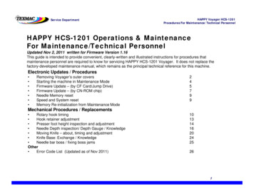
HAPPY Voyager HCS-1201Procedures For Maintenance/Technical PersonnelService DepartmentMechanical Procedures: Movingg Knife TiminggADJUSTING KNIFE TIMINGFollow the procedure below to adjust moving knife timing.1. Remove the needle plate. Do this by loosening each of the two (2) flathead screws with an offset screwdriver.2 Remove the control panel2.panel-sideside side cover (following procedure on page 33. You may also remove the powersupply unit to provide more working space (optional, shown below).First, unplug the power supply as shown.Next, remove the 2 mounting screws. There is 1shown here,, and and additional 1 where it jjoins themain motorFinally, remove this small cover – there are 2phillips-typepp yp screws that hold it in pplace.3. Depress the manual engagement lever. This can be performed with or without the white plastic knob. The levermay not depress completely. Maintain constant downward pressure while performing steps 4 through 8 below.4. Turn the main shaft with a 3mm Allen wrench, clockwise until the manual engagement lever is completely down andthe roller engages into the trim cam. Stop when there is resistance at the main shaft.5 Loosen the trim cam collar.5.collar Do this by loosening the corresponding set screwscrew. (Note: on laterlater-modelmodel VoyagersVoyagers,this is actually 2 semi-circular shaped pieces joined by set screws at opposite ends – in which case, you can try stilljust loosening one of the screws.6. Turn shaft to 115 degrees. Turn the main shaft from the rear of the machine to L 115 (115 degrees).7. Position the cam. Do this by rotating the top of the cam toward you, until it stops against the roller pin, thenmaintainingg lightg ppressure to the left.8. Tighten the trim cam collar. Do this by tightening the corresponding set screw.9. Release the manual engagement lever.Chapter 4: Troubleshooting & Maintenance22 22
Service DepartmentHAPPY Voyager HCS-1201Procedures For Maintenance/Technical PersonnelMechanical Procedures: Movingg Knife TiminggADJUSTING KNIFE TIMING(continued)Shown below are diagrams for the procedure on the previous page – adjusting moving knife timing.Trim cam and collar (indicated by arrow)Illustration: Trim cam and collar fit (single-piece collar ve
program have been frozen by HAPPY font: program have been frozen by HAPPY. 6. Verify updates. After re-booting, you can check firmware version: from the main screen, press MENU, navigate to Other, then select Version to confirm the new firmware version#. 7. Re-Set the machine.