Transcription
Space performance of the multistage labyrinthine SMEI baffleAndrew Buffington*, Bernard V. Jackson**, and P. Paul Hick***Center for Astrophysics and Space Sciences, University of California, San DiegoABSTRACTThe Solar Mass Ejection Imager (SMEI) was launched on 6 January 2003, and shortly thereafter raised to a nearlycircular orbit at 840 km. Three SMEI CCD cameras on the zenith-nadir oriented CORIOLIS spacecraft cover most of thesky beyond about 20 from the Sun, each 102-minute orbit. Data from this instrument provide precision visible-lightphotometric sky maps. Once starlight and other constant or slowly varying backgrounds are subtracted, the residue ismostly sunlight that has been Thomson-scattered from heliospheric electrons. These maps enable 3-dimensionaltomographic reconstruction of heliospheric density and velocity. This analysis requires 0.1% photometry andbackground-light reduction below one S10 (the brightness equivalent of a 10th magnitude star per square degree). Thus10-15 of surface-brightness reduction is required relative to the solar disk. The SMEI labyrinthine baffle provides roughly10-10 of this reduction; the subsequent optics system provides the remainder. We analyze data obtained over two years inspace, and evaluate the full system’s stray-light rejection performance.Keywords: Background-light reduction; space optics; very wide-angle optical designs1. INTRODUCTIONThe CORIOLIS spacecraft, with the Solar Mass Ejection Imager (SMEI)1-6 onboard, was launched on 6 January 2003.Shortly thereafter it was raised to a nearly circular, polar terminator orbit at 840 km. Three SMEI cameras on the zenithnadir oriented spacecraft view most of the sky beyond about 20 from the Sun. Each camera consists of a labyrinthinebaffle protecting the optical pupil from stray light, plus a two-mirror optical system to place the 60 3 field of viewupon a CCD detector. The three cameras are aligned to view together a 160 3 strip oriented roughly perpendicular tothe satellite’s orbital plane, thus providing a nearly complete visible-light sky map each 102-minute orbit. SMEI wasdesigned and constructed by a team of scientists and engineers from the U.S. Air Force Research Laboratory, UCSD, theUniversity of Birmingham UK, Boston College, and Boston University. Financial support is being provided by the AirForce, the University of Birmingham and NASA.A previous article presents calculations and laboratory measurements of the SMEI baffles7. To enable photometricmeasurements of heliospheric structures such as coronal mass ejections, each camera’s combination of baffle and opticsmust meet the stray-light surface-brightness reduction specification of 10-15 relative to the solar disk. By design, thebaffle provides roughly 10-10, and the subsequent optics an additional 10-5. Now that in-space SMEI data are available,end-to-end performance can be evaluated. This article presents results of a stray-light analysis of flight data spanning atwo years period of performance.2. BAFFLE AND OPTICSThe SMEI baffle is described in detail elsewhere7. Figures 1 and 2 show the baffle layout and summarize its stray-lightreduction, for light exiting the baffle’s final aperture Z0, as a function of the incident angles†. However, full end-to-endsystem performance also includes further stray-light rejection provided by the subsequent optics.†The incident angles [Θx, Θy] used here and in the previous article7 represent the intersection of two planes rotated respectively aboutthe Y- and X-axes; the camera points towards the Z-axis and the long direction of its field of view lies along the X-axis. Θx (or Θy) isthe angle between the line of intersection and the Y-Z (or X-Z) plane. The corresponding direction cosines [Cx, Cy] are, respectively,Cx sin(Θx) (1 tan2(Θy) cos2(Θx))-1/2 and Cy sin(Θy) (1 tan2(Θx) cos2(Θy))-1/2. Then, as usual, Cz (1 – Cx2 – Cy2)1/2. Thislatter is the obliquity factor mentioned in §7 of the previous article: the formula given there is correct only in lowest order.Solar Physics and Space Weather Instrumentation, edited by Silvano Fineschi, Rodney A. Viereck,Proc. of SPIE Vol. 5901, 590118, (2005) · 0277-786X/05/ 15 · doi: 10.1117/12.615526Proc. of SPIE Vol. 5901 590118-1
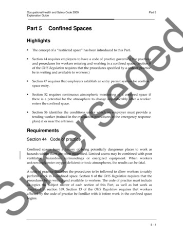
(a) Narrow DimensionZ1 Z2Z3 Z4 Z5Z6 Z7Z8Z0Baffle Centerline010Cm.2030(b) Wide dimensionBaffle CenterlineFigure 1. SMEI baffle design. Aperture numbers Z0 to Z8 advance with distance towards incident light along the baffle centerline.The strategic primary apertures are Z0 (rear of 1st stage and pupil of the subsequent SMEI optics, located out of sight off to the lefthere), Z3 (2nd stage rear), Z6 (3rd stage rear), and finally Z8 (3rd stage front). In the wide dimension the Z3, Z6 and Z8 edges line up,so here the “2nd stage” of the baffle extends from Z3 to Z8 and includes Z6. Secondary apertures Z4 Z7 are placed between Z3 andZ8 to block illumination and/or viewing of the septum bottoms, as described in an earlier article7. All surfaces here are coated withMartin Black8.Proc. of SPIE Vol. 5901 590118-2
Figure 2. Plot of SMEI baffle stray-light rejection versus incident-light angles, normalized to unity at [0,0], from reference 7.Figure 3 shows an exploded view of the optical system and figure 4 is a cross-section showing light rays incident at Θy 0 . In figure 4 light at the center of the field of view (FOV) enters through the final baffle aperture Z0. It then reflectsfrom mirrors M1 and M2 and downward to the CCD. Vane V serves some of the function of coronagraphic Lyot andfield stops by blocking light at wide angles or from outside of the FOV. The light-sensitive portion of the CCD is theleft-hand rectangle in figure 3, whereas the covered (frame-transfer) portion is the right-hand rectangle. These opticalcomponents, except the aperture and CCD, are all mounted to the base plate shown, and this portion of the optics ismounted to the baffle and entirely enclosed by a strongbox structure. The SMEI optics design is an off-axis Newtoniantelescope as viewed in the Y-Z plane (figure 4), combined with a Schmidt camera without its corrector plate, as viewedin the X-Z plane. Mirror M1 was made from a 6061-T6 aluminum ring, diamond-turned to the correct figure, which wasthen separated into quadrants. To avoid stress-relief figure change, the quadrants were separated prior to the finaldiamond turning. The M2 mirrors were made two at a time in half-circles. To avoid increasing wide-angle scatteredlight, all mirrors were not “post-polished”. The optical surface was pure-aluminum-flashed and overcoated with SiOx.Because of the major concern here about stray light, the mirror specification is a surface-brightness reduction of at least10-4, for light scattered by more than 1 . The stray-light distribution of individual flight mirrors was measured using aphotodiode and illuminating a portion of the mirror with a laser. The above specification was confirmed for lightscattering in the direction perpendicular to the residual diamond-turning grooves. In the direction along these grooves,the intensity of scattered light was even smaller, by about a factor of ten. The mirrors were manufactured by HyperfineInc., Boulder CO9. More detail about the optics is provided in the article by Eyles et al.5. The SMEI mission is describedin Jackson et al.6.3.STRAY LIGHT -- REDUCTION IN THE OPTICS BOXWhen light enters through Z0 at angles outside the SMEI photometric FOV (i.e. when Θx 30 , or Θy -1.8 , or Θy 1.5 ), only a portion of it reaches the CCD. When the incident light lies just outside the FOV, the view of the sky isvignetted. Figure 5 illustrates two cases for incident light just outside of the FOV. When 2 Θy 4.2 a portion ofthe light reaches the CCD having reflected only from mirror M1 and not M2 (figure 5b). In this case the light does notenter the photometric FOV, but it often floods the CCD if a bright object such as the Moon is nearby. Data with theMoon inside -3 Θy 4.5 saturate the CCD and must be discarded. Out to Θy 6.5 the Moon still illuminates aportion of M1 and usually causes a shift in the electronic offset which is difficult to model and remove. A similar butsmaller offset shift occurs when Venus lies within the FOV. These data frames are usually also discarded.Proc. of SPIE Vol. 5901 590118-3
BaseFigure 3. Exploded view of the SMEI optics. See also figures 4 and 5. See text for descriptions of the various items shown here.The reflective part of mirror M1 is not illuminated by sky objects having Θy 6.5 . In this case, light entering throughZ0 illuminates the black-anodized interior of the optics box, and can reach the CCD when re-radiated from certain placeson the optics-box top or sides. The CCD FOV subtends typically about 0.01 steradians from these locations. Hence lightreflected and reaching the CCD FOV is reduced by a factor of 20 for the reflectivity, another factor of 300 for the solidangle, and finally is spread out over the equivalent of roughly 200 square degrees of sky, for an expected total surfacebrightness reduction of about 10-6. Thus, for sunlight inside of the limits Θx 58 and Θy 19.5 (the second levelfrom the top in figure 1 above, with baffle rejection between 10-6 and 10-7), the baffle optics rejection is only about 10-12.This would yield a stray-light sky background of between 102 and 103 S10 units (defined above in the abstract). Thisbackground is likely to be unacceptable for 3-dimensional tomographic reconstructions but might be adequate for some2-dimensional image analysis. However, we show below that excessive light outside of the FOV ruins these CCDframes, thus rendering moot such data recovery.Light just outside of the FOV can also interfere with precision photometry if a path within the optics box scatters it intothe photometric FOV. The series of steps, placed as shown below in figure 3 on vane V’s gradual sloped surface nearestmirror M2 and above the CCD, remove background light. Had this surface been smooth, this light would scatter into thephotometric FOV by grazing-angle reflection followed by a reflection from M2. Similarly, the “walls” terminating thesesteps on either end of the stepped section scatter light which in their absence (and a continuation around of the series ofsteps) would be focused safely outside of the photometric FOV. Some of this scattered light reaches the photometricFOV directly following the scattering and another portion after reflecting from M2. This is a small but significant straylight source (here called the “glare”) for the two cameras viewing closest to the Sun. A subtraction procedure, still underdevelopment, yields promising preliminary results and will likely restore full SMEI performance. Strictly speaking, thisstray-light source is not due to the baffle itself and we thus defer detailed discussion to a future article.Proc. of SPIE Vol. 5901 590118-4
4. RESULTS WITH SMEI FLIGHT DATAThe SMEI camera doors were opened at about 2000h GMT on 1 February 2003. About two dozen orbits of“contingency” data were taken with the various onboard-binning modes. Then roughly one orbit for each camera wasrecorded and the full 256 1272 pixel CCD readout sent down through telemetry. This particular calibration sequencehas been repeated annually, and the results presented here are entirely from these data.20Light Incident at 00100203040-4, mm5060700)0 01 01CCotC-otFigure 4. Elevation view of the SMEI optics, a cross-section through the center of figure 3, but with the optical elements now inproper relationship to one another. The baffle structure is off to the left. Corners of the CCD frame are shown as round dots, and thelight-sensitive portion of the CCD (the left-hand rectangle in figure 3) is marked by three triangles. Mirrors M1 and M2 are diamondturned aluminum. The actual top of the optics box is at Yc 85 mm, much higher than shown here; this provides room for the shutterand a larger volume for disposing of unwanted stray light. See figure 9 in reference 5 for a more detailed picture showing the shutter.Figure 5. View as in figure 4, but with axes suppressed and light incident at Θy 2.5 . In (a), rays reflecting from M1 but hitting thetop of M2 are not shown. In (b), the lowest ray, also not shown, intercepts the top of M2 before reaching M1. In each case vane Vintercepts some of the light. In case (b) the light reaching the CCD is outside of the photometric FOV.Proc. of SPIE Vol. 5901 590118-5
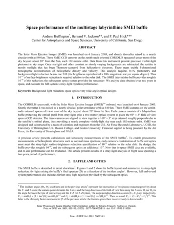
Figures 6 and 7 respectively show three data frames each from camera 3, which views closest to the Sun, and fromcamera 2. These data include the entire available CCD rectangle rather than the usual “region of interest”, a 100 pixelwide circular band extending the full width of the CCD. These figures illustrate most SMEI stray-light features, andsince they span two years in space, also place stringent limits on possible degradation of the Martin-black coating which,together with the baffle geometry, control the amount of stray light. Only a portion of the above circular band is suitableas the photometric FOV, both due to vignetting of the instrument aperture Z0 by other optical elements as seen in figure5, and from the stray-light bands seen in both of these pictures. The photometric FOV is a 60-pixel wide band roughlycentered within the region of interest. This latter band contains the unvignetted view of the sky and also is mostly freefrom stray light.The brightness unit here is an analog-to-digital unit (ADU), one of which on the CCD is 4.7 electrons detected by asingle pixel, each of which in turn covers on average a 0.05 0.05 patch on the sky5. In figure 6, various stars aresuperimposed on a smoother background varying from about 150 ADUs at the end away from the Sun, to about 350ADUs at the end towards it. The corresponding sky surface brightnesses in these areas are about 400 and 900 S10 unitsrespectively. Roughly twice-brighter bands of light occur both above and below this photometric FOV. The lower one issharply cut off by the close edge of vane V, while the upper is more diffuse. These are out-of-focus images of the longedges of the baffle’s aperture Z3. This aperture is illuminated by sunlight entering the front of the baffle, which scattersseveral times before finding its way to the rear of Z3, and then scatters once more through aperture Z0 to reach the SMEIoptics and the CCD. The SMEI optics design places the out-of-focus images of these aperture Z3 vane edges safely justoutside of the photoelectric FOV. The “glare” mentioned above at the end of section 3 is a hard-to-see 30 ADUs broadblob centered at about [100, 200] pixels here, and another half as bright at [1200, 200].In figure 6, the Sun is at [Θx, Θy] [36 , 35 ], so the baffle-only performance (figure 2) for these pictures lies upon the3rd level down from the top at [0 ,0 ] and has an expected light reduction of 10-10. If all of this stray light were to reachthe CCD, it would total about 105 S10 units: here 108 electrons or 2.5 107 ADUs. The inner and outer bands in figure6a respectively contain about 7.4 106 and 6.5 106 ADUs. Thus in this case about half of the stray sunlight enteringthe optics box does reach the CCD, but is largely confined to these two bands, as expected from the original designcalculations.In the pictures of figure 7, camera 2’s axis is at [Θx, Θy] [87 , 30 ], see figure 2. Baffle-only rejection at this location isabout 10-12, so the stray light in the two bands should be reduced about 100-fold; indeed, the contents of the bands arehere reduced to about 2 105 ADUs each. The stray light is mostly confined to the end of the FOV opposite to the Sun.This results from the sunlight initially illuminating only a small part of the outermost septum bottom in the baffle’s widedimension (see figure 1b). From there it scatters once more, toward the opposite side, to pass through the Z3 aperture andthen a second time (reversing its direction) to illuminate the Z3 rear surface. Here geometry favors illuminating that endof Z3 nearest the original illumination.Figure 8 shows the combined data for an entire camera 3 orbit, excluding two portions where the CCD responsesaturated due to well overfilling, a large one due to the Sun, and a smaller one due to the Moon. An onset of the Sun’sexclusion occurs abruptly when this has Θy 19.5 , exactly where expected from the design calculations and earliercalibrations7. In this case a factor of 104 more light floods through the critical aperture Z3 into the baffle’s innermoststage, and much of it passes through Z0 into the optics box. In this case, most of the CCD wells become overfilled,rendering the data frame unusable. To create this figure, the CCD pixels within the photometric FOV for each data framewere transformed into Right Ascension (R.A.) and Declination (δ) coordinates in a hierarchical-triangle sphericalcoordinate system6, using the spacecraft orientation quaternions and known camera orientations5. The observed SMEIsurface brightness (ADUs per pixel) is first corrected for geometrical effects, and then mapped to this coordinate system.Here, for each hierarchical triangle lying within a pixel, the surface brightness is averaged with contributions from theother frames and the result then appropriately binned for the figure.Proc. of SPIE Vol. 5901 590118-6
002001000(a) 4 Feb 2003: 2h 25m 41s2001000(b) 4 Feb 2004: 22h 41m 35s2001000(c) 2 Feb 2005 2h 6m 31s20040060080010001200CCD pixelsFigure 6. Three data frames at roughly one-year intervals from SMEI camera 3, the one viewing closest to the Sun. The intensity scaleis ADUs, where 1 ADU is 4.7 electrons in a pixel. In the 4 second exposure, a 10th magnitude star has about 800 electrons detected inthe CCD. In this figure, an electronic offset pedestal, dark current and a scaled “hot pixel” pattern are removed; individual-pixelimpacts of Earth radiation-belt particles and cosmic rays have been removed by a simple spatial filter. The camera views a roughly 60 long by 3 high rectangle in the sky. In this particular figure the dimension along the arc is roughly parallel to lines of constant R.A.These pictures are left-right reversed from actual sky, and the sky’s rectangular FOV is mapped onto this curved shape by the abovedescribed SMEI optics. The camera axis for the middle frame points towards right ascension R.A. 23h 24m and declination δ 15.5 . The bright star near the center is α Peg, another to the right is γ Peg. At the time of these pictures, the Sun was at R.A. 21h11m and δ -16.2 , about 600 pixels below the origin of coordinates above. Several faint distorted star images are visible also aboveand within the bright arc, coming from stars just north of this FOV, whose light reaches the CCD by slipping under mirror M2 by thepath shown in figure 5b. Noise “aging” in camera 3 is visible as a background of mostly isolated spots whose density is increasingfrom (a) to (c).Proc. of SPIE Vol. 5901 590118-7
001501005002004100014;(a) 3 Feb 2003: 20h 42m 23s20041000(b) 5 Feb 2004: 8h 12m 43s200410004. 'Sa(c) 6 Feb 2005 1h 59m 11s20040060080010001200CCD pixelsFigure 7. Three frames at roughly one-year intervals from SMEI camera 2, the one viewing about 90 from the Sun. The intensityscale is ADUs, note the brightness-scale adjustment relative to figure 6. Here the stray-light bands are visible only on the right handend of the picture, and even there with intensity significantly reduced from figure 6. The camera axis for these pictures points towardsR.A. 13h 6m and declination δ -64.7 . This southerly viewing sometimes places the SMEI spacecraft near the South AtlanticAnomaly, which can contribute significant particle-hit background on the CCD, here especially in (a). Aging in camera 2 is much lessvisible here than in camera 3 (figure 6) because the CCD in camera 2 operates at a significantly colder temperature.5. PERFORMANCE STABILITY OVER TWO YEARSThe annual calibration procedure enables tracking the stray-light performance of SMEI, at present through two full yearsof operation. If the Martin-black coatings degrade with time, the amount of light in the two bands outside of thephotometric FOV will increase in individual data frames like those shown in figures 6 and 7. In figure 6, the contents ofthe bands increases by about 0.5 106 ADUs per year. If this increase is due to an increase in the reflectivity of Martinblack due to contamination or some other temporal change, and if the reflectivity increase is the same factor for each ofthe 4 surfaces encountered before this light can pass through aperture Z0, then a single surface’s reflectivity increasesfor each by a factor of only 1.02 per year. The lower intensity of the bands in figure 7, plus variation in the contributionfrom stars close to or occupying the bands precludes a definitive separate measurement of baffle reflectivity change withtime for camera 2.Proc. of SPIE Vol. 5901 590118-8
-0- 200- 400- 600- 800- 1000- 1200- 1400-1600-1800- 2000- 2200- 2400-2600-2800- 3000C)OLua—degrees0---20½-30--602020221816R.A., hoursFigure 8. A composite of a sequence of frames like figure 6, recorded on 4 February 2003, covering one full orbitbetween 2h 14m 13s and 3h 45m 49s. A small cross marks the Sun’s location at this time. Data are excluded between3h 7m 29s and 3h 36m 37s (the large gap to the lower right in the otherwise nearly full circular pattern) when the Sunhas Θy 19.5 and thus bright stray sunlight overfills the CCD wells. The frames come in groups of typically six separatedby 4 seconds each, and then with a time gap of about 1.5 minutes between groups while data are transferred to thespacecraft onboard buffer. Another smaller gap, to the lower left, is caused by well overfilling from the Moon at R.A. 23h 19.5m and δ -9.9 . Some scattered light is visible nearby this, and nearby Venus which here is at R.A. 17h 58m,δ -21.4 . Also, Mercury is visible as a bright object at R.A. 19h 25m, δ -21.2 .Proc. of SPIE Vol. 5901 590118-9
6. DISCUSSION AND CONCLUSIONSThe final definitive verification of the full 10-15 end-to-end performance of the SMEI baffle and optics combinationawaits a detailed modeling of the zodiacal light and the demonstration of a successful subtraction both of this and ofbackground starlight from SMEI sky maps similar to figure 8. However, figures 6 and 7 both do show that the straybackground light is observed roughly where expected by the original design, and in the right amount. Light intensitydrops off rapidly as one moves from either of the two bands along the narrow dimension of the band, radially towardsand into the photometric FOV. This begins about 1 away from the bands, although some of the light might be picked upwere the photometric FOV not carefully placed. Roughly a factor of 100 dropoff relative to the band’s surface brightnessis required to meet the SMEI specification. If the main mechanism for light in these bands reaching the photometric FOVwere just scattering from mirror M1, the individual-mirror scattering measurements indicate that even better performancethan this would be realized. The “glare” discussed above was unanticipated in the original design, but in a future SMEItype instrument can be reduced by texturing the walls terminating the stepped portion of vane V, and/or coveringreflective portions at both ends of mirror M1 that are not illuminated by light legitimately entering the photometric FOV.If the subtraction procedure for this described above in Section 3 is fully successful, and the verification described at thebeginning of this section is thus realized, then SMEI indeed will have achieved its original stray-light surface-brightnessreduction specification of 10-15 relative to the Sun.ACKNOWLEDGEMENTSThis work was supported in part by grant AF49620-01-1-0054 and subcontract F19628-00-C-0029 from the U.S. AirForce and NASA grant NAG5-134543. SMEI was designed and constructed by a team of scientists and engineers fromthe U.S. Air Force Research Laboratory, the University of California at San Diego, Boston College, Boston University,and the University of Birmingham in the U.K. Financial support was provided by the Air Force, the University ofBirmingham, and NASA.REFERENCES1.2.3.4.5.6.7.8.9.******B.V. Jackson, H.S. Hudson, J.D. Nichols and R.E. Gold, “Design considerations for a ‘solar mass ejectionimager’ on a rotating spacecraft”, in Solar System Plasma Physics, J.H.Waite Jr., J.L. Burch and R.L. Moore,eds., Geophysical Monograph 54, pp. 291-297, 1989.S.L. Keil, R.C. Altrock, S. Kahler, B.V. Jackson, A. Buffington, P.L. Hick, G.M. Simnett, C.J. Eyles, D. Webb,and P. Anderson, “The solar mass ejection imager (SMEI)”, Proc. SPIE 2804, pp. 78-89, 1996.B.V. Jackson, A. Buffington, P. Hick, S.W. Kahler, S.L. Keil, R.C. Altrock, G.M. Simnett and D.F. Webb, “Thesolar mass ejection imager”, Phys. Chem. Earth 22, pp. 441-444, 1997.D.F. Webb, J.C. Johnston, R.R. Radick and the SMEI Team, “The solar mass ejection imager (SMEI): a newtool for space weather”, EOS, Trans. AGU 83, pp. 33, 38-39, 2002.C.J. Eyles, G.M. Simnett, M.P. Cooke, B.V. Jackson, A. Buffington, P.P. Hick, N.R. Waltham, J.M. King, P.A.Anderson and P.E. Holladay, “The solar mass ejection imager (SMEI)”, Solar Physics 217, 319-347, 2003.B.V. Jackson, A. Buffington, P.P. Hick, S.W. Kahler, E. Cliver, S. Price, J. Johnston, P. Anderson, P.E.Holladay, D. Sinclair, T. Kuchar, D. Mizuno, S.L. Keil, R. Radick, J. Mozer, R.C. Altrock, R. Gold, G.M.Simnett, C.J. Eyles, M.P. Cooke, N.R. Waltham and D.F. Webb, “The solar mass ejection imager (SMEI): themission”, Solar Physics 225, 177-207, 2004.A. Buffington, B.V. Jackson and P.P. Hick, “Calculations for, and laboratory measurements of a multistagelabyrinthine baffle for SMEI”, Proc. SPIE 4853, pp. 490-503, 2002.“Optical black coating”, Martin Marietta Company, ibid. 107, pp. 168-169, 1977.Now reorganized as Bach Research Corporation, 2200 Central Avenue, Suite I, Boulder, CO 80301Phone: 303-444-3602; Fax: 303-444-3633; http://www.bachresearch.com.abuffington@ucsd.edu; phone 858-534-6630; fax: 858-534-7051; http://casswww.ucsd.edu/solar/smei/index.html; mailcode 0424, UCSD, 9500 Gilman Drive, La Jolla, CA 92093-0424bvjackson@ucsd.edu; phone 858-534-3358; fax: 858-534-2294pphick@ucsd.edu; phone 858-534-8965; fax: 858-534-0177Proc. of SPIE Vol. 5901 590118-10
Plot of SMEI baffle stray-light rejection versus incident-light angles, normalized to unity at [0,0], from reference 7. Figure 3 shows an exploded view of the optical system and figure 4 is a cross-section showing light rays incident at 4 y 0q. In figure 4 light at the center of the field o