Transcription
EUROCODESA tool for building safety andreliability enhancementEU-Russia cooperation on standardisation for construction – Moscow, 9-10 October 2008EUROCODE 1Actions on Building StructuresPaolo FormichiCEN/TC250/SC1University of Pisa (Italy)1
EUROCODESA tool for building safety andreliability enhancementEU-Russia cooperation on standardisation for construction – Moscow, 9-10 October 2008Scope of the presentation: illustrate Eurocode 1: Actions on Structures, itsarchitecture and general principles with reference tobuildings background and pre-normative studies illustrate the main concepts and design philosophy forsome parts of Eurocode 1.2
EUROCODESA tool for building safety andreliability enhancementThe Eurocode programmeEU-Russia cooperation on standardisation for construction – Moscow, 9-10 October 2008EN Number The Structural Eurocodes (58 parts)3N ofPartsEN 1990Eurocode: Basis of structural design1EN 1991Eurocode 1: Actions on structuresEN 1992Eurocode 2: Design of concrete structures4EN 1993Eurocode 3: Design of steel structures20EN 1994Eurocode 4: Design of composite steel andconcrete structures3EN 1995Eurocode 5: Design of timber structures3EN 1996Eurocode 6: Design of masonry structures5EN 1997Eurocode 7: Geotechnical design3EN 1998Eurocode 8: Design of structures for earthquakeresistance6EN 1999Eurocode 9: Design of aluminium structures310
EUROCODESA tool for building safety andreliability enhancementThe Eurocode 1 packageEU-Russia cooperation on standardisation for construction – Moscow, 9-10 October 2008EN 1991part4PublishedEN 1991-1-1Densities, self weight, imposed loads for buildings2002EN 1991-1-2Actions on structures exposed to fire2002EN 1991-1-3Snow loads2003EN 1991-1-4Wind actions2005EN 1991-1-5Thermal actions2003EN 1991-1-6Actions during execution2005EN 1991-1-7Accidental actions2006EN 1991-2Traffic loads on bridges2003EN 1991-3Actions induced by cranes and machinery2006EN 1991-4Silos and tanks2006
EUROCODESA tool for building safety andreliability enhancementFormat of the Eurocode 1EU-Russia cooperation on standardisation for construction – Moscow, 9-10 October 20085Each part of Eurocode 1 (except part 1-2 on Actions on structuresexposed to fire) is made up by the following sections:- Foreword- Section 1:- Section 2:- Section 3:- Section 4 .:- AnnexesGeneralClassification of ActionsDesign SituationsRepresentation of actions (specific rules for thedefinition of each action’s values)(Normative or Informative)
EUROCODESA tool for building safety andreliability enhancementFormat of the Eurocode 1EU-Russia cooperation on standardisation for construction – Moscow, 9-10 October 20086The Foreword is common for all EC1 parts and contains informationon:- The Structural Eurocode programme;- The Status and Field of Application of Eurocodes;- National Standards implementing Eurocodes;- Links between Eurocodes and harmonised technical specifications(ENs and ETAs) for products;- Additional information specific for each part;- National Annex for each part.
EUROCODESA tool for building safety andreliability enhancementFormat of the Eurocode 1EU-Russia cooperation on standardisation for construction – Moscow, 9-10 October 20087National Standards implementing EurocodesNational AnnexEuropean Commission recognises the responsibility of regulatoryAuthorities in each EU member state in the determination of valuesrelated to safety matters at national level through a NationalAnnex.The National Annex may only contain information on thoseparameters, which are left open in the Eurocode for national choice,known as Nationally Determined Parameters (NDPs).
EUROCODESA tool for building safety andreliability enhancementFormat of the Eurocode 1EU-Russia cooperation on standardisation for construction – Moscow, 9-10 October 20088Nationally Determined Parameters (NDPs)Differences in geographical or climatic conditions (e.g. wind or snow maps)or in ways of life, as well as different levels of protection that may prevail atnational, regional or local level, can be taken into account through NDPsspecifying:– values and/or classes where alternatives are given in the Eurocode;– values to be used where a symbol only is given in the Eurocode;– country specific data (geographical, climatic, etc.) e.g. snow map;– procedure to be used where alternative procedures are given in theEurocode.The National Annex may also contain:– decisions on the application of informative annexes;– references to non contradictory complementary information to assist theuser to apply the Eurocode.
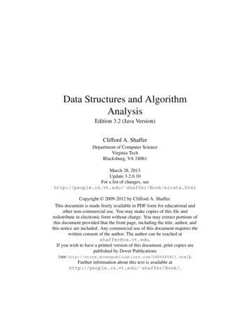
EUROCODESFormat of the Eurocode 1A tool for building safety andreliability enhancementEU-Russia cooperation on standardisation for construction – Moscow, 9-10 October 20089Nationally Determined Parameters (NDPs)1500 NDPs in the Eurocode suite355 NDPs in EN 1991EN 19989%EN 19975%EN 19964%EN 19952%EN 19996%EN 19944%EN 19903%EN 199124%EN 199215%EN 199328%
EUROCODESA tool for building safety andreliability enhancementFormat of the Eurocode 1EU-Russia cooperation on standardisation for construction – Moscow, 9-10 October 200810Section 1 - General1.1 Scope1.2 Normative references1.3 Distinction between Principles and Application Rules1.4 Terms and definitionsThe Principles comprise:- general statements and definitions for which there is noalternative, as well as- requirements and analytical models for which no alternativeis permitted unless specifically stated.The Application Rules are generally recognised rules whichcomply with the Principles and satisfy their requirements.
EUROCODESFormat of the Eurocode 1A tool for building safety andreliability enhancementEU-Russia cooperation on standardisation for construction – Moscow, 9-10 October 200811Section 2 – Classification of ActionsPermanent (G)Variation intimeVariable (Q)Accidental (A)OriginSpatialvariationNature and/orStructuralresponseDirect (e.g. forces)Indirect (e.g. temperature)Fixed (e.g. self weight)Free (e.g. predeformation)StaticDynamic
EUROCODESA tool for building safety andreliability enhancementFormat of the Eurocode 1EU-Russia cooperation on standardisation for construction – Moscow, 9-10 October 200812Section 3 – Design situationsEN 1990 3.2(1)P The relevant design situations shall be selectedtaking into account the circumstances under which the structureis required to fulfil its function.EN 1990 3.2(2)P Design situations shall be classified as follows:– persistent design situations, which refer to the conditions ofnormal use;– transient design situations, which refer to temporary conditionsapplicable to the structure, e.g. during execution or repair;– accidental design situations, which refer to exceptional conditions applicable to the structure or to its exposure, e.g. to fire,explosion, impact or the consequences of localised failure;– seismic design situations, which refer to conditions applicableto the structure when subjected to seismic events.
EUROCODESA tool for building safety andreliability enhancementFormat of the Eurocode 1EU-Russia cooperation on standardisation for construction – Moscow, 9-10 October 2008ULS Design situations (EN1990)Persistent/transient design situationsAccidental design situationsSeismic design situations13
EUROCODESEN 1991-1-1A tool for building safety andreliability enhancementEU-Russia cooperation on standardisation for construction – Moscow, 9-10 October 200814EN 1991-1-1 Densities, self weight, imposed loads for buildingsEN 1991-1-1 gives design guidance and actions for the structural designof buildings and civil engineering works including some geotechnicalaspects for the following subjects:- Densities of construction materials and stored materials;- Self-weight of construction works;- Imposed loads for buildings.Background documents:- ISO 9194 Basis for Design of Structures – Actions due to Self-Weight of Structures, non StructuralElements and Stored materials – Density;- CIB Report 115/89Int. Council for research and innovation in building and construction Actions onStructures, Self-Weight Loads;- CIB Report 116/89Int. Council for research and innovation in building and construction Actions onStructures, Live Loads in Buildings;- National Standards of CEN member states;
EUROCODESA tool for building safety andreliability enhancementEN 1991-1-1 – Imposed LoadsEU-Russia cooperation on standardisation for construction – Moscow, 9-10 October 200815Imposed loads (characteristic values) – Categories of occupancy (Example)CategorySpecific Useqk[kN/m2]Qkqk[kN][kN/m]0.2 to 1.0(0.5)AAreas for domestic andresidential activities (floors)1.5 to 2.02.0 to 3.0BOffice areas2.0 to 3.01.5 to 4.5CAreas where people may congregate:DC1: Areas with tables (e.g. restaurants,cafés )2.0 to 3.03.0 to 4.0C2: Areas with fixed seats (e.g. areas inchurches, theatres or cinemas )3.0 to 4.02.5 to 7.0 (4.0)C3: Areas without obstacles for movingpeople (e.g. museums, exhibitionrooms )3.0 to 5.04.0 to 7.0C4: Areas with possible physical activities(e.g. dance halls, gymnastic rooms )4.5 to 5.03.5 to 7.0C5: Areas susceptible to large crowds(e.g. concert halls )5.0 to 7.53.5 to 4.53.0 to 5.0D1: Areas in general retail shops4.0 to 5.03.5 to 7.0 (4.0)0.8 to 1.0D2: Areas in department stores4.0 to 5.03.5 to 7.00.2 to 1.0(0.5)0.8 to 1.0Shopping areas:
EUROCODESA tool for building safety andreliability enhancementEN 1991-1-1 – Imposed LoadsEU-Russia cooperation on standardisation for construction – Moscow, 9-10 October 2008166.2.1 Floors Beams and Roofs(1)P For the design of a floor structure within one storey or a roof, theimposed load shall be taken into account as a free action applied at the mostunfavourable part of the influence area of the action effects considered.(2) Where the loads on other storeys are relevant, they may be assumed tobe distributed uniformly (fixed actions).
EUROCODESA tool for building safety andreliability enhancementEN 1991-1-1 – Imposed LoadsEU-Russia cooperation on standardisation for construction – Moscow, 9-10 October 200817Specific rules for the reduction of the imposed load on Beamsψ0 is the combination factor according to EN 1990, may be taken as:0,7 for residential, social and commercial areas1,0 for storage and industrial areasA0 10,0 m21.20A is the influence areaαAψ 0 1.0ψ 0 200A [m ]
EUROCODESA tool for building safety andreliability enhancementEN 1991-1-1 – Imposed LoadsEU-Russia cooperation on standardisation for construction – Moscow, 9-10 October 200818Specific rules for the reduction of the imposed load on Columns in residential areas,offices, areas with congregation of people and shopping centres.The total imposed load from several storeys may be multiplied by a reduction factor αnqk,mqk,iqk,iqk,iqk,iqk,i5 storeys above the columnn is the number of storeys ( 2) above the loaded structural elements from the samecategory.ψ0 is in accordance with EN 1990 (may be taken equal to 0,7).αn1.00n 5αn 040n50
EUROCODESA tool for building safety andreliability enhancementEN 1991-1-3 Snow LoadsEU-Russia cooperation on standardisation for construction – Moscow, 9-10 October 200819EN 1991-1-3 Snow LoadsEN 1991-1-3 provides guidance for the determination of the snowload to be used for the structural design of buildings and civilengineering works for sites at altitudes under 1500m.In the case of altitudes above 1500m advice may be found in theappropriate National Annex.Snow loads in general are classified as variable/accidental, direct,fixed, static actions.
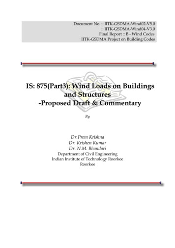
EUROCODESEN 1991-1-3 Snow LoadsA tool for building safety andreliability enhancementEU-Russia cooperation on standardisation for construction – Moscow, 9-10 October 200820Snow Loads as Accidental ActionsExceptional snowload on theground0.79Exceptional snowdrifts1.30Gumbel probability paper: Pistoia (IT) k sm/sk 1,65
EUROCODESA tool for building safety andreliability enhancementEN 1991-1-3 Snow LoadsEU-Russia cooperation on standardisation for construction – Moscow, 9-10 October 200821Background documents:EN 1991-1-3 is mainly based on:- ISO 4355 Bases for design of structures – Determination of snow loadson roofs- the results of a research work, carried out between 1996 and 1999,under a contract specific to this Eurocode, to DGIII/D3 of the EuropeanCommission.In the research work (1996-1999) they were identified four main tasks: study of the European ground snow load map investigation and treatment of exceptional snow loads study of conversion factors from ground to roof loads definition of ULS and SLS combination factors for snow loads.http://www2.ing.unipi.it/dis/snowloads/
EUROCODESA tool for building safety andreliability enhancementContents of EN 1991-1-3 – Snow LoadsEU-Russia cooperation on standardisation for construction – Moscow, 9-10 October 200822ForewordSection 1: GeneralSection 2: Classification of actionsSection 3: Design situationsSection 4: Snow load on the groundSection 5: Snow load on roofsSection 6: Local effectsANNEX A: Design situations and load arrangements to be used forANNEX B:ANNEX C:ANNEX D:ANNEX E:different locationsSnow load shape coefficients for exceptional snow driftsEuropean Ground Snow Load MapsAdjustment of the ground snow load according to return periodBulk weight density of snow
EUROCODESA tool for building safety andreliability enhancementEN 1991-1-3 – Snow LoadsEU-Russia cooperation on standardisation for construction – Moscow, 9-10 October 200823The snow load on the roof is derived from the snow load onthe ground (sk), multiplying by appropriate conversion factors(shape, thermal and exposure coefficients).s μi Ce Ct sksk is intended as the upper value of a random variable, forwhich a given statistical distribution function applies, with theannual probability of exceedence set to 0,02 (i.e. a probability ofnot being exceeded on the unfavourable side during a“reference period” of 50 years).The characteristic ground snow loads (sk) are given by theNational Annex for each CEN country.
EUROCODESA tool for building safety andreliability enhancementEN 1991-1-3 – Snow LoadsEU-Russia cooperation on standardisation for construction – Moscow, 9-10 October 200824Ground Snow Load DatabaseData from 2600 weather stationsfrom 18 countriesElaborations with common statisticalproceduresGround Snow Load Map10 Climatic RegionsWith homogeneous climaticfeatures
EUROCODESA tool for building safety andreliability enhancementEN 1991-1-3 – Snow LoadsEU-Russia cooperation on standardisation for construction – Moscow, 9-10 October 2008Alpine Region – Snow load at sea level(France, Italy, Austria, Germany andSwitzerland) A 2 sk (0,642 Z 0,009 ) 1 728 z Zone number given on the mapA site altitude above Sea Level [m]25
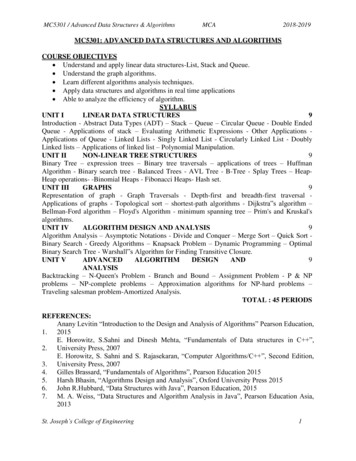
EUROCODESA tool for building safety andreliability enhancementEN 1991-1-3 – Snow LoadsEU-Russia cooperation on standardisation for construction – Moscow, 9-10 October 200826Snow Loads on roofss μi Ce Ct skThe snow the snow layers on a roof can have many different shapes depending onroof’s characteristics (shape, thermal properties, roughness, exposure, local climate,surrounding terrain, etc.)UNDRIFTED LOAD ARRANGEMENTIn absence of wind, or with very low windvelocities ( 2 m/s) snow deposits on the roof in abalanced way and generally a uniform cover isformed.DRIFTED LOAD ARRANGEMENTFor situations where the wind velocity increasesabove 4 5 m/s snow particles can be picked upfrom the snow cover and re-deposited on the leesides, or on lower roofs in the lee side, or behindobstructions on the roof.wind
EUROCODESA tool for building safety andreliability enhancementEN 1991-1-3 – Snow LoadsEU-Russia cooperation on standardisation for construction – Moscow, 9-10 October 200827Snow Loads on RoofsValues for shape coefficients μi given in EN 1991-1-3 are calibrated ona wide experimental campaign, both in situ and in wind tunnel.s μi Ce Ct sk1,491,92Average 1,6730 Multi-span drifted case
EUROCODESA tool for building safety andreliability enhancementEN 1991-1-4 – Wind ActionsEU-Russia cooperation on standardisation for construction – Moscow, 9-10 October 200828EN 1991-1-4 Wind ActionsEN 1991-1-4 gives guidance on the determination of natural wind actions forthe structural design of building and civil engineering works for each of theloaded areas under consideration. This includes the whole structure or partsof the structure or elements attached to the structure, e.g. components,cladding units and their fixings, safety and noise barriers.StructureField of application of EN 1991-1-4BuildingsMaximum height 200 mBridgesMaximum span 200 mWind Actions are classified as variable, fixed, direct actions.According to the structural response:- quasi-static response (the majority of building structures)- dynamic aeroelastic response (lightweight structureschimneys)e.g. steel
EUROCODESA tool for building safety andreliability enhancementContents of EN 1991-1-4 – Wind ActionsEU-Russia cooperation on standardisation for construction – Moscow, 9-10 October 2008ForewordSection 1:Section 2:Section 3:Section 4:Section 5:Section 6:Section 7:Section 8:ANNEX A:ANNEX B:ANNEX C:ANNEX D:ANNEX E:ANNEX F:GeneralDesign situationsModelling of wind actionsWind velocity and velocity pressureWind actionsStructural factor CsCdPressure and force coefficientsWind actions on bridgesTerrain effectsProcedure 1 for determining the structural factor CsCdProcedure 2 for determining the structural factor CsCdCsCd for different types of structuresVortex shedding and aeroelastic instabilityDynamic characteristics of structures29
EUROCODESA tool for building safety andreliability enhancementEN 1991-1-4 – Wind ActionsEU-Russia cooperation on standardisation for construction – Moscow, 9-10 October 200830Wind pressuresThe characteristic peak velocity pressure qp is the main parameter forthe determination of the wind actions on structures and accounts for themean wind and the turbulence component. EN 1991-1-4 indicates qp as afunction of:Wind climate, through the basic windvelocity vb at a given site;Local factors, such as terrainroughness [cr(z)], orography [c0(z)];Height above the terrain (z).
EUROCODESA tool for building safety andreliability enhancementEN 1991-1-4 – Wind ActionsEU-Russia cooperation on standardisation for construction – Moscow, 9-10 October 200831Wind actions on structures may be calculated as:Wind Pressures on both external andinternal surfaces;Wind Forces, directly or as the summationof wind pressures acting over referencesurfacesqp(z) peak velocity pressure for the given location (site basic velocity, terrainroughness, orography etc.), function of the reference height zcppressure coefficient (internal or external) depending on the location of thereference area in the structurecfforce coefficient, depending on the size ratios of the structural elementcscd structural factor takes into account the effect on wind actions from the nonsimultaneous occurrence of peak wind pressures on the surface (cs) togetherwith the effect of the vibrations of the structure due to turbulence (cd)Aref reference area: portion of the structure or structural element.
EUROCODESA tool for building safety andreliability enhancementEN 1991-1-4 – Wind ActionsEU-Russia cooperation on standardisation for construction – Moscow, 9-10 October 200832Example of pressure coefficientsDuoptch RoofZe hAt θ 0 the External Pressure changes rapidly between positive andnegative values on the windward face around a pitch angle of θ -5 to45 , so both positive and negative values are given.
EUROCODESA tool for building safety andreliability enhancementEN 1991-1-4 – Wind ActionsEU-Russia cooperation on standardisation for construction – Moscow, 9-10 October 2008Structural factor CsCd (example of calculation - Annex D)Structural factor takesinto account the effect onwind actions from the nonsimultaneous occurrenceof peak wind pressureson the surface (Cs)together with the effect ofthe vibrations of thestructureduetoturbulence (Cd).33
EUROCODESA tool for building safety andreliability enhancementEN 1991-1-7 – Accidental ActionsEU-Russia cooperation on standardisation for construction – Moscow, 9-10 October 200834EN 1991-1-7 Accidental ActionsEN 1991-1-7 provides strategies and rules for safeguardingbuildings and other civil engineering works againstidentifiable and unidentifiable accidental actions.They are defined:– strategies based on identified accidental actions (e.g.an impact from a delivery lorry in a supermarket),– strategies based on limiting the extent of localisedfailure (e.g. consequence of a natural gas explosion).
EUROCODESA tool for building safety andreliability enhancementContents of EN 1991-1-7 – AccidentalActionsEU-Russia cooperation on standardisation for construction – Moscow, 9-10 October 2008ForewordSection 1:Section 2:Section 3:Section 4:Section 5:35GeneralClassification of actionsDesign situationsImpactInternal ExplosionsANNEX A: (Informative) Design for consequences of localisedfailure in buildings from an unspecified causeANNEX B: (Informative) Information on risk assessmentANNEX C: (Informative) Dynamic design for impactANNEX D: (Informative) Internal Explosions
EUROCODESA tool for building safety andreliability enhancementEN 1991-1-7 – Accidental ActionsEU-Russia cooperation on standardisation for construction – Moscow, 9-10 October 2008Strategies for Accidental Design Situations36
EUROCODESA tool for building safety andreliability enhancementEN 1991-1-7 – Accidental ActionsEU-Russia cooperation on standardisation for construction – Moscow, 9-10 October 200837Example of identifiable accidental actions - Impact from vehiclesHard impact may be determined by dynamic analysis or modelled byequivalent static design collision forces.
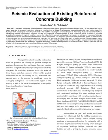
EUROCODESA tool for building safety andreliability enhancementEN 1991-1-7 – Accidental ActionsEU-Russia cooperation on standardisation for construction – Moscow, 9-10 October 200838Example of identifiable accidentalactions - ExplosionsGas explosions account for the majority ofaccidental explosions in buildings. Gas iswidely used and, excluding vehicularimpact, the incidence of occurrence of gasexplosions in buildings is an order ofmagnitude higher than other accidentalloads causing medium or severe damagethat may lead to progressive ordisproportionate collapse.The disproportionate collapse at Ronan Point– East London May 16th 1968
EUROCODESA tool for building safety andreliability enhancementEN 1991-1-7 – Accidental ActionsEU-Russia cooperation on standardisation for construction – Moscow, 9-10 October 200839Key elements of a structure should be designed to withstand the effects ofan internal natural gas explosion, using a nominal equivalent staticpressure is given by:pd 3 pvor pd 3 0,5 pv 0,04/(Av/V)2whichever is the greater, where:- pv is the uniformly distributed static pressure in kN/m2 at which ventingcomponents will fail;- Av is the area of venting components;- V is the volume of room.The explosive pressure acts effectivelysimultaneously on all of the boundingsurfaces of the room.
EUROCODESA tool for building safety andreliability enhancementEN 1991-1-7 – Accidental ActionsEU-Russia cooperation on standardisation for construction – Moscow, 9-10 October 200840Limiting the extent of localised failureDesigning a building such that neither the whole building nor a significant partof it will collapse if localised failure were sustained, is an acceptable strategy.Adopting this strategy should provide a building with sufficientrobustness to survive a reasonable range of undefined accidentalactions depending on their possible consequences.Example of design procedures: provide adequate horizontal ties aroundand internally to each floor (minimumaxial forces to design ties are given) provide vertical ties (columns should bedesigned to resist tensile loads –explosions) ensure that upon the notional removalof a supporting column, beam or wall,the damage does not exceed 15% of thefloor area.
EUROCODESA tool for building safety andreliability enhancementEN 1991-1-7 – Accidental ActionsEU-Russia cooperation on standardisation for construction – Moscow, 9-10 October 200841Safety differentiationCollapse may cause particularly large consequences in terms of injury to humans,damage to the environment or economic losses for the society. In practice this meansthat Eurocode 1, Part 1.7 accepts the principle of safety s of buildings andcivil engineering worksRecommended strategies to limit theconsequences of localised failure in buildingsfrom an unspecified causeCC3High consequence for loss ofhuman life, or economic, social orenvironmental consequences verygreatGrandstands, public buildingswhere consequences of failureare high (e.g. a concert hall)- risk analysis- horizontal ties, together with vertical ties, in allsupporting columns and walls should be provided,or alternatively- the building should be checked to ensure thatupon the notional removal of each supportingcolumn and each beam supporting a column, orany nominal section of load-bearing wall (one at atime in each storey of the building) the buildingremains stable and that any local damage doesnot exceed a certain limit.CC2Medium consequence for lossof human life, economic, socialor environmental ngs,publicbuildingswhere consequences of failureare medium (e.g. an officebuilding)Provision of effective horizontal ties, or effectiveanchorage of suspended floors to walls should beprovided.CC1Low consequence for loss ofhuman life, and economic, socialor environmental consequencessmall or negligibleAgricultural buildings wherepeople do not normally enter(e.g.storagebuildings),greenhousesNo further specific consideration is necessarywith regard to accidental actions from unidentifiedcauses.Definition of consequence classes Annex B EN1990
EUROCODESA tool for building safety andreliability enhancementEN 1991EU-Russia cooperation on standardisation for construction – Moscow, 9-10 October 2008http://eurocodes.jrc.ec.europa.eu/Thank you for your attention.42
EN 1990 Eurocode: Basis of structural design 1 N of Parts EN Number The Structural Eurocodes (58 parts) EU-Russia cooperation on standardisation for construction – Moscow, 9-10 October 2008 4 EUROCODES A tool for building