Transcription
s from a WorkshopMichael PeroneDepartment of PsychologyWest Virginia University
2EditionFirst edition, created April 30, 2017Author’s Contact InformationMichael PeroneDepartment of PsychologyWest Virginia University53 Campus DriveMorgantown, WV ntsDescriptions of, and advice about, Arduino coding techniques, anddevelopment of the sketches herein, were informed and guided bymaterial at www.arduino.cc and the Arduino Programming Notebook,August 2007 edition, by Brian W. Edwards.The circuit drawings were prepared with Fritzing software available atwww.fritzing.org.The website https://arduino-info.wikispaces.com was a valuableresource, particularly in preparing the circuits and sketches involving thestepper motor and the infrared remote control.A few illustrations were adapted from open-source materials designed byLinz Craig, Nick Poole, Prashanta Aryal, Theo Simpson, Tai Johnson, andEli Santistevan of Sparkfun Electronics.The physical computing schematic in Part 1 was contributed to the publicdomain by Nevit Dilmen (Own work) [CC0], via Wikimedia Physical computing.svg).The “Anatomy of a C function” in Part 4 is claration.The resistor decoder in the Quick Reference is by Bret nseThis work is licensed under the Creative CommonsAttribution-NonCommercial-ShareAlike 4.0 International LicenseTo see a copy of the license, a/4.0/
3ContentsIntroduction . 5Part 1: Physical Computing & Basic Prototyping MaterialsThe Arduino Uno Microcontroller. 6Physical Computing . 8Building Prototypes with an Arduino and a Breadboard . 10Part 2: Sensors & ActuatorsButtons . 11Potentiometers and Their Kin . 11Advanced Sensors . 12Light Emitting Diodes (LEDs) . 13Piezo Speakers . 13Liquid Crystal Display (LCD) Panels . 13Motors. 14Personal Computers. 15Part 3: Circuit ElementsResistors . 16NPN Transistors. 16Optcouplers. 17Relays . 17Part 4: Programming ElementsArduino Integrated Development Environment (IDE) . 19Arduino Libraries . 19Basic Structure of an Arduino Sketch. 20Variables and Constants . 21Array Variables . 22Arithmetic Operators . 22Comparison Operators. 23Boolean Operators . 23Functions . 24Part 5: Common Programming TasksCommunication through the Serial Port . 26Timing. 28Digital Input. 30Digital Output. 34Analog Input . 35Analog Output . 36Branching . 38Looping. 40Doing Math . 40Making Sounds . 43
4Part 6: Sample Sketches & CircuitsBlink (with circuit drawing) . 45Reading Serial Strings. 46Reading Serial Strings as Parameters (with circuit drawing) . 48Count Button Presses (with circuit drawing) . 50Count Button Presses Debounced . 52Adjustable Tone (with circuit drawing). 54LCD Hello World (with circuit drawing) . 56LCD Recycling Hello World . 60Thermistor. 62Joystick Simple . 63Joystick Refined. 64Joystick RGB LED . 66Joystick Ultrasonic RGB LED . 68Servo Sweep. 72Photocell . 73Photocell Response Count . 74Two Buttons . 76Stepper Sweep . 78Stepper by Steps . 79Stepper by Degrees . 80Temperature Humidity Monitor . 82Remote Signal Reception . 83Remote Signal Decoding Elegoo . 84Transistor to Relay (with circuit drawing) . 86Optocoupler Test (with circuit drawing) . 88Analog IO with PWM (with circuit drawing) . 90Part 7: Exercises. 92Resources .94AppendicesOverview . 96Elegoo Uno Project Super Starter Kit . 97Escobar & Perez-Herrera (2015) . 98Stepper 360 Dial. 107Quick Reference .109
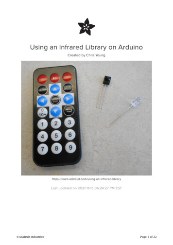
5IntroductionThis document pulls together, in what I hope is a handy format, some topics explored in a “microcontrollerworkshop” in the WVU Department of Psychology in the spring semester of 2017. This is not intended to be acomprehensive treatment of anything in particular, but rather a compendium of information that I think isinteresting or useful. My conception of what is “interesting” or “useful” is that of an experimental psychologistwho sees microcontroller technology as a means of supporting basic research. Your individual needs may leadyou to a different opinion. Still, I hope there is enough overlap between us to make this material helpful to you.The workshop was largely a show-and-tell: Each participant bought a kitwith an Arduino Uno microcontroller development board, a breadboardand jumper wires, and a variety of devices for detecting events in theworld or making events happen in the world – this being the essence ofphysical computing. Each week we assembled a few circuits with some ofthe devices and paired each circuit with an Arduino “sketch” (program) tomake it go. The idea was to illustrate how you can handle inputs andcontrol outputs with relatively straightforward code and simple circuits.We used the Elegoo Uno Project Super Starter Kit, and we fooled around with these devices: For input: buttons, potentiometer, joystick, photoresistor (a.k.a photocell), thermistor, DHT11 temperatureand humidity module, infrared receiver and handheld remote control For output: light emitting diodes (LEDs), liquid crystal display (LCD) panel, servo motor, stepper motor, activebuzzer, passive buzzer Circuit elements: resistors, NPN transistor, relay, 4N25 optocoupler (the last was my addition; it was notincluded in the kit), and – of course – the Arduino Uno, breadboard, and jumper wires.Some weeks into the semester, we recognized that our circuits weresuffering from loose connections, partly because the Arduino andbreadboard were separate parts that could move and put strain on thejumper wires, and partly because the Elegoo breadboard was, well,maybe not of the highest quality. We made improvements by using anAdafruit mounting plate to hold the Arduino firmly aligned with a halfsize breadboard.This Reference is organized into seven sections as described in the tableof contents. Parts 1 through 3 provide simple (one might say “simplistic”– but give me some slack, I’m a psychologist, not an electrical engineer) descriptions of the hardware used in theworkshop. Part 4 describes essential elements of Arduino programming. This material is not comprehensive byany stretch of the imagination, but it does cover what you need to know to get started on some serviceablecoding projects. Part 5 describes some ways to accomplish common tasks; these ways are not the only ways –they may not even be the best ways – but they are fairly easy to understand and they work. Part 6 reproducessome of the sketches and circuits we used in the workshop in case it may be useful to have them at hand. Part 7offers some exercises to give you practice in coding.You can find the official reference for Arduino programming at www.arduino.cc/en/Reference/HomePage. Andyou can find an excellent set of tutorials at www.arduino.cc/en/Tutorial/HomePage. When you have a specificproblem to solve, a bit of Googling can be a time-saver: The members of the large Arduino programmingcommunity have a wide range of interests and experience, and they are generous in sharing their knowledge.
6Part 1: Physical Computing &Basic Prototyping MaterialsThe Arduino Uno MicrocontrollerHere, shown larger than life, is the Elegoo company’s version of the venerable Arduino Uno Revision 3(hereafter, “the Arduino”). This is an essential part our physical computing tool kit for building prototypes ofcircuits that can sense and control environmental events.The Arduino can be powered through a USB cable attached to a personal computer (PC). It also has a power jackso it can be powered with a 9V battery or a plug-in power supply that provides between 7V and 12V. Regardlessof the power source, the Arduino will regulate the voltage downward: It operates at 5V.Along the top of the Arduino (as it is oriented in this photo) are 14 digital pins numbered 0 through 13. Thesecan be configured as inputs to sense discrete (digital) events such as button presses, or as outputs to makethings happen by turning devices on and off. Pins 0 and 1 are used when the Arduino communicates with the PCthrough the USB cable; to avoid interference, we won’t use them. Note that six of the pins are marked withdashes: 3, 5, 6, 9, 10, and 11. These pins are capable of pulse width modulation (PWM) which is a method forsimulating analog output using digital pins. Digital devices have only two states on and off or, in electronicterms, HIGH (5 volts for our Arduino) or LOW (0 volts). The state of an analog device is continuously variable.Pulse width modulation simulates an analog output signal by alternating between HIGH and LOW at frequenciesestablished by the programmer. More information about PWM is in Part 5 of this Reference.At the bottom right of the Arduino are six analog input pins numbered A0 through A5. Whereas a digital inputcan detect only HIGH and LOW states (5V and 0V), an analog pin can detect a wide range of states anywherebetween 5V and 0V. More information about analog input is in Part 5. See also the Quick Reference section,which includes a table summarizing the functions of all 20 of the input/output pins.
7Also along the bottom of the Arduino are several power-related pins. Our interest is in the pins labeled 5V andGND (ground, 0V). The 5V pin is akin to the positive terminal of a battery, and the GND pin is akin to thenegative terminal. There’s another GND pin on the top of the board, next to Digital Pin 13. Electric currentflows when an appropriate device completes acircuit between 5V and GND. The circuit illustratedat right turns on a light emitting diode (LED). Thepositive lead of the LED is connected to 5V and thenegative lead is attached to GND via a resistor.(Even though the Arduino’s power is modest, itwould burn out the LED quickly without thatresistor.)In this circuit, the Arduino is not doing anythinginteresting; it is just being used to power the LED.We are treating the Arduino as if it were a battery.Of course we want the Arduino to do more, such asturning things on and off under the control of aprogram.The Arduino plays a more interesting role in thesecond circuit, to the left. As before, the negativelead of the LED is connected to GND through aresistor. The positive lead, however, is connectedto Digital Pin 13. With this arrangement, we canprogram the Arduino to use the pin to outputcurrent to the LED, turning the LED on by settingthe pin to HIGH and turning it off by setting thepin to LOW.Programs that run on the Arduino are called“sketches.” Sketches are written on the PC in avariant of the C programming language anduploaded to the Arduino through the USB cable.The sketch will run continuously whenever theArduino is powered. To stop the sketch, you can disconnect the Arduino’s power source (e.g., by unplugging theUSB cable) or press the reset button mounted on the upper left corner of the board. The reset button only stopsthe sketch momentarily: After about a second, it starts over.Information and advice about writing Arduino code can be found in Parts 4 and 5, and over two dozen of thesketches prepared for the workshop can be found in Part 6 (complete with embarrassing typographical errors inthe comments and awkward code here and there). Sketches can be written using the Arduino IntegratedDevelopment Environment described in Part 4. It is available for free at www.arduino.cc.
8Physical ComputingThe term physical computing is applied toarrangements of computer hardware and softwarethat interact with the environment by detectingevents and making things happen. The diagramshows the essential parts. In our case, the“interactive system” is the Arduino microcontrollerand the sketch that is running on it. The “realworld” is that part of the environment that can affect the Arduino or be affected by it. Sensors are devices thatprovide a way for the environment to affect the Arduino through its input pins. Actuators are devices thatprovide a way for the Arduino to affect the environment though its output pins or serial communications port.Electronic circuits connect the sensors and actuators to the Arduino’s input and output pins, and the Arduino’ssoftware (the sketch) determines how the Arduino will interpret information from the sensors and control theactuators.Physical computing is ubiquitous in modern life. Consider your microwave oven. Its embedded microcontrollerinteracts with the world by receiving your commands through a keypad. By pressing a few keys on the outsideof the oven, you can tell it how long to cook and at what power level. The microcontroller interprets your keypresses and activates devices that, for example, generate radio waves that heat your food and start the motorthat turns the food in circles. Your oven probably has some internal sensors, too, that transmit information tothe microcontroller about the state of the food you are cooking. For example, a sensor might measure thetemperature of the food and the microcontroller’s software may respond by turning off the radio waves andcarousel motor when the target temperature is reached.As a physical computing system, the microwave oven interacts with a pretty small part of the world. Othersystems are more expansive. Home security systems employ a wide range of sensors to detect motion, thesound of breaking glass, the concentration of carbon monoxide, smoke, water in places where it shouldn’t be,and whether specific doors and windows are open. The systems can respond to the information from thesesensors by texting the homeowner, sounding an alarm, orcalling the police or fire department.Physical computing is common in basic experimentalpsychology. Researchers in the experimental analysis ofbehavior could be said to have gotten an early start. Aprecursor of today’s systems came into wide use in thesecond half of the twentieth century thanks to B. F. Skinnerand Ralph Gerbrands of Harvard University. They developeda system of controlling events in behavioral test chambersand recording the responses of animals using circuits thatcombined electromechanical switches, steppers, relays,counters, motors, and timers. The system had sensors –lever switches to detect behavior – and actuators – lamps,speakers, and food dispensers for delivering stimuli. Therewere no microcontrollers to control this stuff; instead, thesystems used rather sophisticated electromechanical circuitssuch as the one behind B. F. Skinner in the photo at right.(To learn more about this period in the history ofexperimental psychology, visit the Behavioral ApparatusVirtual Museum curated by Kennon A. Lattal ataubreydaniels.com/institute/museum.)
9Electromechanical control circuits were eventually replaced bycomputer technology. First came minicomputers which, bytoday’s standards, weren’t all that “mini.” When fullyequipped with the components needed to store programs anddata – components such as a paper tape puncher/reader(surprisingly common in the 1970s because they providedcheap storage) or disk drives (expensive) – a minicomputermight stand six feet tall and anywhere from about two to fivefeet wide.The first mass-produced minicomputer was the PDP-8 from theDigital Equipment Corporation. (“PDP” was short for“Programmable Data Processor.”) It served as the hardwareplatform for a programming language developed specifically tocontrol behavioral experiments and collect data. Thelanguage, “SKED” (and later, “Super SKED” and “SKED-11”) wasdesigned by Arthur Snapper at Western Michigan University,implemented on the PDP-8 (and later the PDP-11), and widelyused for about 20 years starting in the early 1970’s.In the late 1980’s, Thomas Tatham, a behavior analyst trainedat Temple University, developed a variant of SKED for thedesktop microcomputers that had become popular. Thelanguage, originally called Med State Notation, was first sold byMed Associates, Inc. in 1987 along with a system of hardwaremodules and cables to link the computer to behavioral testchambers (the company also sold the chambers). Thelanguage, renamed MED-PC, has been upgraded several times.Today, Med’s software and hardware, in conjunction with a PC,is probably the most widely used physical computing system inexperimental psychology.The Med system has a significant limitation: it costs a lot ofmoney. A system based on the Arduino can be made withoutmuch money, but it requires substantial technical knowledge plus the time and inclination to tinker and build.The purpose of the microcontroller workshop is to introduce young behavior analysts to physical computingwith the Arduino, in the hope that some of them might be inspired to tinker and build.Rogelio Escobar, a professor of psychology at the National AutonomousUniversity of Mexico, has achieved a high degree of technical sophisticationin the development of electronic equipment for experimental control andbehavioral recording. He has done magnificent work in creating physicalcomputing systems for the study of operant behavior, and he generouslyshares his work – in both hardware and software – on his web site,http://analisisdelaconducta.net/. His work is not restricted to physicalcomputing; he also has designed the experimental environments in whichbehavior take place: the test chamber. His website includes files you canuse to build rat chambers using a 3D printer!An article by Dr. Escobar and his student Carlos A. Perez-Herrera, publishedin the Journal of the Experimental Analysis Behavior, is included as an appendix to this Reference. The articledescribes a physical computing system that uses an Arduino to interface behavioral test chambers with a PCrunning a Visual Basic program.
10Building Prototypeswith an Arduino and a BreadboardOur Arduino is intended for building prototypes of physicalcomputing systems. Header strips mounted on the edgesof the board allow you to connect wires simply by pushingone end into the header. Circuits with sensors andactuators are built on a “breadboard” that has rows of tinysockets that likewise allow you to insert buttons, LEDs,resistors, etc., by pushing their leads into the sockets andto connect them to one another by pushing wires into thesockets. Building circuits this way is relatively quick andeasy – no soldering – but the resulting product is fragile. Ifyou need a durable version of your circuit, you will need tosolder the microcontroller and various circuit elements together – a task beyond the scope of our littleworkshop.A typical breadboard, shown below alongside an Arduino, has four sections. The sections on each edge have twovertical columns of sockets. The sockets in each column are connected to one another. This means that a wireinserted into any socket within a column is electrically connected to the wires inserted into other sockets withinthe same column. Thesesections are called “powerrails” because theynormally are used as aconvenient way to getGND and 5V to the partsof a circuit. As in theillustration, a wire is runfrom a GND pin on theArduino to one of thesockets in the columnlabeled “—.” Now all thesockets in that column areconnected to GND.Another wire is run from a5V pin on the Arduino toone of the sockets in the“ ” column, so that thesockets in that column areconnected to positive.The two middle sectionsare organized intohorizontal rows. Withineach section, the five sockets in each row are connected. This allows you connect various components withoutsolder. Consider the red LED in the illustration. One of its leads is connected to a resistor which itself isconnected to GND. The other lead is connected to a wire that is connected to Pin 6 of the Arduino.As you build circuits on your breadboard, remember: The sockets on the power rails are connected vertically forthe full length of the board. The sockets in the middle sections are connected horizontally in sets of five.
11Part 2:Sensors & ActuatorsButtonsAs already noted, digital inputs have two states, LOW and HIGH, corresponding to 0V (i.e., GND)and 5V. If you are building a prototype circuit, the simplest way to figure digital input into thedesign is with an electrical switch, commonly in the form of a push button. In our workshop, weuse a common button like the one shown here. It has two sets of leads, each pair constitutingthe end points of a switch. Pressing the button connects the two leads. If the switch is in aproperly designed circuit, pressing the button causes electrical current to flow across the leads.Although there are two switches in this device, there is only one button and pressing it operates the left switchand the right switch simultaneously. The button is designed to be mounted across the gap running down themiddle of your breadboard. This keeps the left switch and the right switch from interfering with one another.The illustration at rightshows the kind o
This Reference is organized into seven sections as described in the table of contents. Parts 1 through 3 provide simple (one might say “simplistic” – but give me some slack, I’m a psychologist, not an electrical engineer) descriptions of the hardware used in the workshop. Part 4 describes es