Transcription
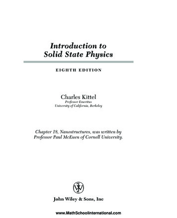
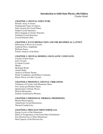
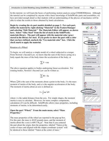
Introduction to Solid Modeling Using SolidWorks 2006COSMOSMotion TutorialPage 1In this tutorial, we will learn the basics of performing motion analysis using COSMOSMotion. Althoughthe tutorial can be completed by anyone with a basic knowledge of SolidWorks parts and assemblies, wehave provided enough detail so that students with an understanding of the physics of mechanics will beable to relate the results to those obtained by hand calculations.Begin by creating the six part models detailed on page 2. For each part,define the material by right-clicking “Material” in the FeatureManagerand selecting “Edit Material.” The Materials Editor will appear, as shownhere. Select “Alloy Steel” from the list of steels in the SolidWorksmaterials library. The part will appear with the material color (gray)stored in the library for steel. If you prefer to show the part with a colorthat you have defined, uncheck the “Use material color” box. Click thecheck mark to apply the material.Rotation of a WheelTo begin, we will analyze a simple model of a wheel subjected to a torque.From Newton’s Second Law, we know that the sum of the forces acting on abody equals the mass of the body times the acceleration of the body, or F maThe above equation applies to bodies undergoing linear acceleration. Forrotating bodies, Newton’s Second Law can be written as: M IαWhere M is the sum of the moments about a point in the body, I is the massmoment of inertia of the body, and α is the angular acceleration of the body.The moment of inertia about an axis is defined as:I mr 2 dVwhere r is the radial distance from the axis. For simple shapes, the momentinertia is easy to calculate. However, for more complex components,calculation of I can be difficult. SolidWorks allows mass properties, includingmoments of inertia, to be determined easily.Open the part “Wheel.” From the main menu, select “MassProperties.”The mass properties of the wheel are reported in the pop-up box.For this part, the mass is 40.02 pounds-mass, and the moment ofinertia about the z-axis is 609.3 lbmin2. Note that if you centeredthe part about the origin, then the properties, labeled “Taken at thecenter of mass and aligned with the output coordinate system” willbe identical to those labeled “Taken at the center of mass.”
Introduction to Solid Modeling Using SolidWorks 2006COSMOSMotion TutorialPage 2
Introduction to Solid Modeling Using SolidWorks 2006COSMOSMotion TutorialPage 3Since the wheel is symmetric about the axis of rotation, it will be difficult to visualize the rotationalmotion in the model. Adding a non-symmetric pattern to one of the faces of the wheel will be helpful.Select the face shown here. Click onthe Textures Tool, and select atexture. The “Checker 1” texturefrom the “Patterns” group is a goodchoice. Move the scale slider barunder the preview window to make the patternlarger or smaller, as desired. Click the checkmark to apply the pattern to the face.Save the part file. Open the part “Wheel2.”Find the mass properties, and apply a textureto a face of the model. Save the part file.Note that the mass of this part (40.14 lbm) is almost identical to that of the other wheel, but the massmoment of inertia (837.0 lbmin2) is about 37% greater. The mass moment of the part depends not only onthe part’s mass, but also on how that mass is distributed. As more mass is placed further away from theaxis of the part, then the mass moment of inertia about that axis increases (note the “r2” in the equation onpage 1).Open a new assembly. Insert the component “Frame.”Since the first component inserted into an assembly is fixed, it is logical toinsert the component representing the stationary component (the “frame” or“ground” component) first.Activate the COSMOSMotion program by selecting Tools: Add-Insfrom the main menu. Select COSMOSMotion from the menu ofavailable add-ins and click OK.
Introduction to Solid Modeling Using SolidWorks 2006COSMOSMotion TutorialWith COSMOSMotion activated, a “Motion” menu will be added to themain menu. Also, a tab to the motion model will appear above theFeatureManager.Click the Motion icon above the FeatureManager.A pop-up box will appear, asking if you would like to add the existingparts to Grounded or Moving Parts.Click Yes to add the frame link as a grounded (stationary) part inthe motion model.Notice that the frame part is listed under “Ground Parts” in the motionmodel manager.You can switch back to the modelingenvironment by clicking on theFeatureManager icon. However, youcan perform modeling functions(adding components, adding mates,etc.) while in the motion model environment.Insert the part “Wheel” into the assembly. Click Yes to add thepart to the motion model.From the menu, select Motion: Show SimulationPanel.Click on the Calculate button. A pop-up box will appearas shown here.Page 4
Introduction to Solid Modeling Using SolidWorks 2006COSMOSMotion TutorialPage 5The box that appears shows an analysis of the model. Each moving part has six degrees of freedom in 3D space. The part can translate along the x, y, and z axes, and can rotate about the x, y, and z axes. Sincewe have one moving part (the wheel), and its motion is so far unconstrained, the number of degrees offreedom is six.Click Dismiss to close the message box. Select the Mate Tool.Add a concentric mate between the center hole of the wheeland and one of the holes in the frame link. Be sure to selectthe cylindrical faces for the mate and not edges.A message box will appear, informing you that a concentric jointhas been created based on the mate.Click Dismiss to close the message box.Aconcentric jointhas been added. By zooming in on the joint area, you can see the jointillustrated (shown here with the model in wireframe mode for clarity). Eachjoint restricts degrees of freedom. The cylindrical joint prevents translationin the x and y directions, and also prevents rotations about the x and y axes.Therefore, two degrees of freedom (DOF) remain: the wheel can turn aboutthe z axis and can also translate along the z axis.In the Simulation Panel, click theCalculate button.The message box confirms that twodegrees of freedom remain in themodel.Add a coincident matebetween the back face ofthe wheel and the frontface of the frame link.
Introduction to Solid Modeling Using SolidWorks 2006COSMOSMotion TutorialPage 6Dismiss the message box confirming the creation of a joint from the mate. Click the Calculatebutton in the Simulation panel.The message box now shows thatthe joint has been changed into arevolute joint. A revolute jointallows only one degree of freedom.It is represented by a hinge icon.Close the Mate Command window, and dismiss the message box.We will now apply a prescribed rotational motion to the revolute joint,and determine the torque required to produce the motion.Right-click the Revolute joint under Joints in the Motion ModelManager. Select Properties.Choose the motion type as Acceleration. (The “Motion On” will beset to Rotate Z, with no other choices available, since that is the onlymotion allowed by the revolute joint.)Set the type of acceleration as constant, and the value as 600deg/s2.Note that if you calculate the number of DOF, it is now zero, as theonly unconstrained motion now is being “driven” by the prescribed motionadded to the joint.Click the Simulation Settings icon in the Simulation Panel.Under the Simulation tab, set the duration to 2 seconds and thenumber of frames to 100.Run the simulation by clicking the calculatoron the Simulation Panel.
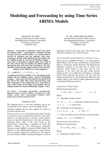
Introduction to Solid Modeling Using SolidWorks 2006COSMOSMotion TutorialPage 7Right-click the Revolute joint inthe Motion Model Manager.Choose Plot: Angular Velocity: ZComponent.Note that when you right-click onthe joint, a different menu appearsthan before. After a simulation hasbeen performed, the menus allowyou to display results. If you wantto change the parameters of the simulation, then you mustfirst delete the results of the last simulation.A plot of the angular velocity is displayed. Since wespecified a constant acceleration, the velocity change islinear. The final velocity after 2 seconds is:deg deg ω αt 600 2 ( 2 s ) 1200s s The appearance of the plot can be changed with commands similar to those for spreadsheet graphs. Forexample, the background color can be changed by right-clicking in the graph are and selecting ChartProperties. The appearance of the line (color/weight) can be changed by right-clicking on the curve andselecting Curve properties.Make any desired changesto the appearance of theplot.We will now plot the value of the torque that is desiredto drive the wheel at the specified motion.Right-click the Revolute joint in the Motion ModelManager. Choose Plot: Rotary Motion Generator:Moment Z. Modify the appearance of the chart asdesired.The plot created shows a constant value of torque.
Introduction to Solid Modeling Using SolidWorks 2006COSMOSMotion TutorialRight-click on the y-axis and select AxisProperties. Under the Numbers tab,change the number of decimal places to 2.The torque required to produce the motion isseen to be 16.53 in·lb.We can check this result by applying the equation M IαDelete the simulation results by clicking on the calculator icon in theSimulation Panel. Right-click on the part name (Wheel) and selectProperties.Since we defined the material of the wheel when creating the part, we canleave the source of the properties as “Part”. The mass moment of intertiaabout the Z-axis that was previously calculated (609.3 lbm·in2) isshown.It is necessary to use a consistent set of units to apply thisequation. The mass properties of the wheel were calculated withlbm (pounds-mass) as the units of mass.A pound is a measure of weight, not mass. A pound-mass is themass of an object that weighs one pound at sea level.To convert weight in pounds to mass, it is necessary to divide bythe gravitational constant, 32.2 ft/s2 or 386.4 in/s2. Since the inchis our unit of length, we will use the latter. Therefore I, the massmoment of inertia, is:609.3lb in 2I 1.577 lb in s 2in386.4 2sThe angular acceleration α must be expressed in radians per second squared:deg π rad rad α 600 2 10.47 2s 180 deg s The torque can now be calculated as:rad ΣM T Iα (1.577 lb in s 2 ) 10.47 2 16.5 in l bs This result agrees with the COSMOSMotion result.Page 8
Introduction to Solid Modeling Using SolidWorks 2006COSMOSMotion TutorialPage 9Note that the torque required to produce the constant acceleration is also constant. Therefore, the torquewould need to be applied instantaneously, which is impossible. If our goal is to reach a constant angularvelocity of 1200 deg/s (200 rpm) in 2 seconds, then we may consider a motion profile that starts with anacceleration of zero and ramps up to a maximum value and then ramps back down to zero. In this case,the torque is allowed to ramp up and down smoothly.Click the calculator icon on the Simulation Panel to deletethe previous results. Right-click on the Revolute joint inthe Motion Model Manager and change the Motion Type toVelocity. Select a Step Function with an initial value of 0deg/s, a final value of 1200 deg/s, a start time of 0 seconds,and an end time of 2 seconds. Click Apply, and run thesimulation.The graphs previously created are refreshed. Note that theangular velocity profile is an S-shaped curve, as theacceleration (the slope of the velocity curve) begins and ends atzero and peaks in the middle. The torque now smoothlyincreases to a maximum value at a time one second andsmoothly decreases back to zero. Although the peak torque(24.79 in·lb) is higher than before, the smooth torque curve ispreferred. In particular, the jerk (rate of change of acceleration) is no longer infinite.Delete the results. Set the duration of thesimulation to 3 seconds. Repeat thesimulation.Notice that the angular velocity remains at1200 deg/s after 2 seconds. Also, the torqueremains at zero. If no friction is present in themodel, then maintaining a constant rotationalspeed requires no torque.
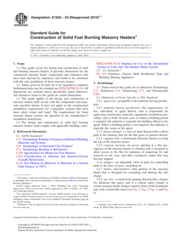
Introduction to Solid Modeling Using SolidWorks 2006COSMOSMotion TutorialPage 10Return to the FeatureManager and deletethe Wheel part. Insert Wheel 2, and addconcentric and coincident mates asbefore. Switch to the Motion ModelManager, and set the properties of therevolute joint to velocity, with a stepfunction as described above. Run thesimulation.Note that the peak torque is 34.05 in·lb,which is 37% higher than before. Thisincreased torque is proportional to theincreased moment of inertia of the newwheel.Analysis of a 4-Bar LinkageWe will now analyze the motion of the 4-barlinkage shown here. We will specify a constantrotational velocity for the crank and will find thevelocities and accelerations of the other links, thetorque required to drive the mechanism, andforces at the pin joints.FNOTE: This analysis will not predict the stressesin the links, since the links are assumed to berigid. However, the forces calculated can be usedas inputs to finite element analysis.CONNECTOROpen a new assembly. Insert the frame link, andthen insert the other three links in theapproximate locations shown.CRANKSwitch to the motion model.When prompted to add theparts to grounded andmoving parts in the motionmodel, click Yes. Open the Simulation Panel.FRAMEThroughout this tutorial, any message boxescan be deleted by selecting Dismiss.Note that there are 18 DOF, six for each of the three moving links.Click the calculator icon to run the simulation.The moving links will all fall off the screen, as the motion model includes gravity.Click the calculator icon again to clear the results and reset the components.ROCKER
Introduction to Solid Modeling Using SolidWorks 2006COSMOSMotion TutorialAdd a coincident mate between the back face of the crank and the frontface of the frame. Add a concentric mate between the correspondingcylindrical faces of the frame
Introduction to Solid Modeling Using SolidWorks 2006 COSMOSMotion Tutorial Page 1 In this tutorial, we will learn the basics of performing motion analysis using COSMOSMotion. Although the tutorial can be completed by anyone with a basic knowledge of SolidWorks parts and assemblies, we have provided enough detail so that students with an understanding of the physics of mechanics will be able to .