Transcription
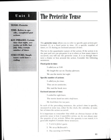
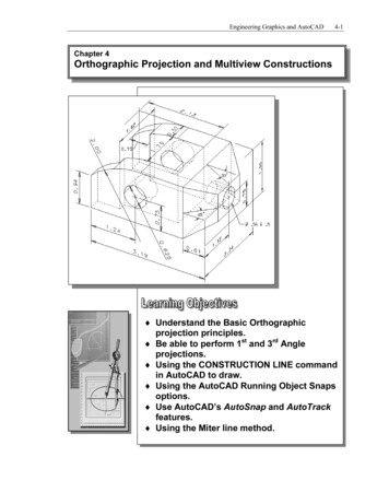
Engineering Graphics and AutoCAD4-1Chapter 4Orthographic Projection and Multiview Constructions Understand the Basic Orthographicprojection principles. Be able to perform 1st and 3rd Angleprojections. Using the CONSTRUCTION LINE commandin AutoCAD to draw. Using the AutoCAD Running Object Snapsoptions. Use AutoCAD’s AutoSnap and AutoTrackfeatures. Using the Miter line method.
Visit our website to learn more about this and other books:
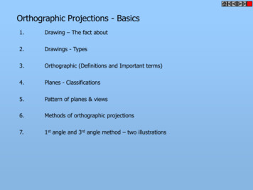
4-2Engineering Graphics and AutoCADIntroduction3D ObjectMultiview drawing(2D Views)Most drawings produced and used in industry are multiview drawings. Multiviewdrawings are used to provide accurate three-dimensional object information on twodimensional media, a means of communicating all of the information necessary totransform an idea or concept into reality. The standards and conventions of multiviewdrawings have been developed over many years, which equip us with a universallyunderstood method of communication.Multiview drawings usually require several orthographic projections to define the shapeof a three-dimensional object. Each orthographic view is a two-dimensional drawingshowing only two of the three dimensions of the three-dimensional object. Consequently,no individual view contains sufficient information to completely define the shape of thethree-dimensional object. All orthographic views must be looked at together tocomprehend the shape of the three-dimensional object. The arrangement and relationshipbetween the views are therefore very important in multiview drawings. Before taking amore in-depth look into the multiview drawings, we will first look at the concepts andprinciples of projections.
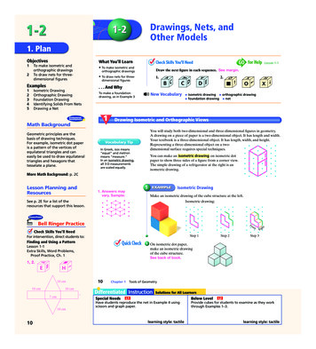
Orthographic Views and Multiview Constructions4-3Basic Principle of ProjectionTo better understand the theory of projection, one must become familiar with theelements that are common to the principles of projection. First of all, the POINT OFSIGHT (aka STATION POINT) is the position of the observer in relation to the objectand the plane of projection. It is from this point that the view of the object is taken.Secondly, the observer views the features of the object through an imaginary PLANE OFPROJECTION (or IMAGE PLANE). Imagine yourself standing in front of a glasswindow, IMAGE PLANE, looking outward; the image of a house at a distance issketched on to the glass and is a 2D view of a 3D house.Orthographic ProjectionThe lines connecting from the Point of Sight to the 3D object are called the ProjectionLines or Lines of Sight. Note that in the above figure, the projection lines are connectedat the point of sight, and the projected 2D image is smaller than the actual size of the 3Dobject.Now, if the projection lines are parallel toeach other and the image plane is alsoperpendicular (normal) to the projectionlines, the result is what is known as anorthographic projection. When theprojection lines are parallel to each other,an accurate outline of the visible face ofthe object is obtained.The term orthographic is derived from theword orthos meaning perpendicular or90º.
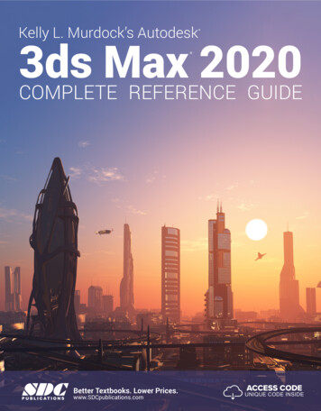
4-4Engineering Graphics and AutoCADIn Engineering Graphics, the projection of one face of an object usually will not providean overall description of the object; other planes of projection must be used. To create thenecessary 2D views, the point of sight is changed to project different views of the sameobject; hence, each view is from a different point of sight. If the point of sight is movedto the front of the object, this will result in the front view of the object. And then movethe point of sight to the top of the object and looking down at the top, and then move tothe right side of the object, as the case may be. Each additional view requires a new pointof sight.Principal Views(Each with it’s point of sight )Multiview Orthographic ProjectionIn creating multiview orthographic projection, different systems of projection can be usedto create the necessary views to fully describe the 3D object. In the figure below, twoperpendicular planes are established to form the image planes for a multivieworthographic projection.The angles formed betweenthe horizontal and the verticalplanes are called the first,second, third, and fourthangles, as indicated in thefigure. For engineeringdrawings, both first angleprojection and third angleprojection are commonlyused.
Orthographic Views and Multiview ConstructionsFIRST-ANGLE PROJECTION In first-angle projection, the object is placed in front of the image planes. And theviews are formed by projecting to the image plane located at the back.4-5
4-6Engineering Graphics and AutoCADRotation of the Horizontal and Profile Planes In order to draw all three views of the object on the same plane, the horizontal (TopView) and profile (Right Side view) are rotated into the same plane as the primaryimage plane (Front View).
Orthographic Views and Multiview Constructions4-7Getting the 3D Adjuster Model through the Internet AutoCAD 2007 allows us to share files and resources through the Internet.Drawings can be placed and opened to an Internet location, insert blocks by draggingdrawings from a web site, and insert hyperlinks in drawings so that others can accessrelated documents. Note that to use the AutoCAD 2007 Internet features, MicrosoftInternet Explorer 6.0 (or a later version) and Internet or Intranet connections arerequired.We will illustrate the procedure to open an AutoCAD file from the Internet byUniform Resource Locator (URL).1. Select the AutoCAD 2007 option on the Program menu or select theAutoCAD 2007 icon on the Desktop.2. In the AutoCAD Startup dialog box, select Open a Drawing with a singleclick of the left-mouse-button.3. In the Select File dialog box, enterhttp://www. sdcACAD.com/acad2007/Adjuster1stAngle.dwgas shown in the figure below.4. Click the Open icon and the file is downloaded from thewww.sdcACAD.com web site to the local computer. The URL entered must be of the Hypertext Transfer Protocol (http://) and thecomplete filename must be entered including the filename extension (.dwg or .dwt).
4-8Engineering Graphics and AutoCADDynamic Rotation – 3D Orbit1. Select 3D Orbit in the Viewpull-down menu.[View] [Orbit] [Free Orbit] The Free Orbit view displays an arcball, which is a circle, divided into fourquadrants by smaller circles. Free Orbit enables us to manipulate the view of 3Dobjects by clicking and dragging with the left-mouse-button.2. Inside the arcball, press down the left-mouse-button and drag it up and downto rotate about the screen X-axis. Dragging the mouse left and right will rotateabout the screen Y-axis.3. On your own, use the real-time dynamic rotation feature of the Free Orbitcommand and examine the relations of the 2D views, projection planes andthe 3D object.
Orthographic Views and Multiview Constructions4-9Third-Angle Projection In third-angle projection, the image planes are placed in between the object and theobserver. And the views are formed by projecting to the image plane located in frontof the object.
4-10Engineering Graphics and AutoCADRotation of the Horizontal and Profile Planes In order to draw all three views of the object on the same plane, the horizontal (TopView) and profile (Right Side view) are rotated into the same plane as the primaryimage plane (Front View). Using the Internet Explorer, open the following avi file to view the rotationof the projection planes:http://www. sdcACAD.com/acad2007/AdjusterRTOP.avi
Orthographic Views and Multiview Constructions4-11Examining the 3rd Angle Projection1. Click the Open icon in the Standard toolbar area asshown.2. In the Select File dialog box, enter the following file gle.dwg3. Click the Open icon and the Adjuster file is downloaded from thewww.sdcACAD.com web site to the local computer.4. Select 3D Orbit in the View pulldown menu.[View] [Orbit] [Free Orbit]5. On your own, examine the relationsof the 2D views, projection planesand the 3D object.
4-12Engineering Graphics and AutoCADThe Glass Box and the Six Principal ViewsConsidering the third angle projection described in the previous section further, we findthat the object can be entirely surrounded by a set of six planes, a Glass box. On theseplanes, views can be obtained of the object as it is seen from the top, front, right side, leftside, bottom, and rear. Consider how the six sides of the glass box are being opened up into one plane. Thefront is the primary plane, and the other sides are hinged and rotated into position.
Orthographic Views and Multiview Constructions4-13 In actual work there is rarely an occasion when all six principal views are needed onone drawing, but no matter how many are required, their relative positions need to bemaintained. These six views are known as the six principal views. In performingorthographic projection, each of 2D views shows only two of the three dimensions(height, width, and depth) of the 3D object
4-14Engineering Graphics and AutoCADExamining the Glass Box Model1. Click the Open icon in the Standard toolbar area asshown.2. In the Select File dialog box, enter the following file Box.dwg3. Click the Open icon and the Adjuster file is downloaded from thewww.sdcACAD.com web site to the local computer.4. Select 3D Orbit in the View pulldown menu.[View] [Orbit] [Free Orbit]5. On your own, examine the relationsof the 2D views, projection planesand the 3D object.
Orthographic Views and Multiview Constructions4-15Alphabet of LinesIn technical Engineering drawings, each line has a definite meaning and is drawn inaccordance to the line conventions as illustrated in the figure below. Two widths of linesare typically used on drawings; the thick line width should be 0.6 mm and the thin linewidth should be 0.3 mm.Visible LineCutting-Plane LinesHidden LineCenter LineDimension Line, Extension LinePhantom LineBreak Line
4-16Engineering Graphics and AutoCADVisible Line Visible lines are used to represent visible edges and boundaries. The lineweight is thick, 0.6mm/0.024″).Hidden Line Hidden lines are used to represent edges and boundaries that are notvisible from the viewing direction. The line weight is thin, 0.3mm/0.012″.Center Line Center lines are used to represent axes of symmetry. The line weight isthick, 0.3mm/0.012″.Dimension Line, Extension Line and Leader Dimension lines are used toshow the sizes and locations of objects. The line weight is thick, 0.3mm/0.012″.Cutting Plane Lines Cutting Plane lines are used to represent the location of animaginary cut has been made, so that the interior of the object can be viewed. The lineweight is thick, 0.6mm/0.024″. (Note that two forms of line type can be used.)Phantom Line Phantom lines are used to represent imaginary features or objects,such as a rotated position of a part. The line weight is thick, 0.3mm/0.012″.Break Line Break lines are used to represent imaginary cut, so that the interior of theobject can be viewed. The line weight is thick, 0.6mm/0.024″.
Orthographic Views and Multiview Constructions4-17Precedence of LinesIn multiview drawings, coincidence lines may exist within the same view. For example,hidden features may project lines to coincide with the visible object lines. And centerlines may occur where there is a visible or hidden outline.In creating a multiview drawing, the features of the design are to be represented,therefore object and hidden lines take precedence over all other lines. And since thevisible outline is more important than hidden features, the visible object lines takeprecedence over hidden lines. As shown in the below figure.The following list gives the order of precedence of lines:1. Visible object lines2. Hidden lines3. Center line or cutting plane line4. Break lines5. Dimension and extension lines6. Crosshatch/section linesIn the following sections, the general procedure of creating a 3rd angle three-vieworthographic projection using AutoCAD is presented.
4-18Engineering Graphics and AutoCADThe Locator Design Before going through the tutorial, make a rough sketch of a multiview drawing of thepart. Based on your knowledge of AutoCAD 2007 so far, how would you arrangeand construct these 2D views? Take a few minutes to consider these questions and dopreliminary planning by sketching on a piece of paper. You are also encouraged toconstruct the orthographic views on your own prior to following through the tutorial.(Download the 3D Locator model by opening up the following arting Up AutoCAD 20071. Select the AutoCAD 2007 option on the Program menu or select the AutoCAD2007 icon on the Desktop.
Orthographic Views and Multiview Constructions4-192. In the Startup dialog box, select the Start from Scratch option with a singleclick of the left-mouse-button.Metric3. In the Default Settings section, pick Metric as the drawing units.4. Click OK to accept the settings and exit the Startup window.GRID and SNAP Intervals Setup1. In the pull-down menus, select:[Tools] [Drafting Settings]2. In the Drafting Settings dialog box,select the SNAP and GRID tab if itis not the page on top.3. Change Grid Spacing to 0.5 for bothX and Y directions.4. Also adjust the Snap Spacing to 0.5for both X and Y directions.5. Pick OK to exit the Drafting Settings dialog box.
4-20Engineering Graphics and AutoCADLayers setup1. Pick Layer Properties Manager in theObject Properties toolbar.2. Click on the New icon to create new layers.3. Create two new layers with the following neTypeContinuousContinuous4. Highlight the layer Construction in the list of layers.5. Click on the Current button to set layer Construction asthe Current Layer.6. Click on the OK button to accept the settings and exit the LayerProperties Manager dialog box.7. In the Status Bar area, reset the option buttons so that only SNAP, GRID, andMODEL are switched ON.
Orthographic Views and Multiview Constructions4-21Drawing Construction Lines Construction lines are lines that extend to infinity. Construction lines are usually usedas references for creating other objects. We will also place the construction lines onthe Construction layer so that the layer can later be frozen or turned off.1. Select the Construction Line icon in the Draw toolbar.In the command prompt area, the message “ xline Specify apoint or [Hor/Ver/Ang/Bisect/Offset]:” is displayed. To orient construction lines, we generally specify twopoints. Note that other orientation options are alsoavailable.2. Select a location near the lower left corner of the graphicswindow. It is not necessary to align objects to the worldcoordinate origin. CAD systems provide us with manypowerful tools to manipulate geometry. Our main goal is touse the CAD system as a flexible and powerful tool, and tobe very efficient and effective with the systems.3. Pick a location above the last point to create a vertical construction line.4. Move the cursor toward the right of the first point and pick a location to createa horizontal construction line.5. Inside the graphics window, right-mouse-click to end the Construction Linecommand.6. In the Status Bar area, turn OFF the SNAP option.Using the Offset command1. Select the Offset icon in the Modify toolbar. In the commandprompt area, the message “Specify offset distance or[Through/Erase/Layer]:” is displayed.2. In the command prompt area, enter: 5.0 [ENTER].3. In the command prompt area, the message “Select object tooffset or exit :” is displayed. Pick the vertical line on thescreen.
4-22Engineering Graphics and AutoCAD4. AutoCAD next asks us to identify the direction of the offset. Pick a locationthat is to the right of the vertical line.5. Inside the graphics window, right-mouse-click to end the Offset command.6. Hit the [SPACE BAR], or right-mouse-click inside thegraphics window and select Repeat Offset in the popup list,to repeat the Offset command.7. In the command prompt area, enter: 2.5 [ENTER].8. In the command prompt area, the message “Select object to offset or exit :”is displayed. Pick the horizontal line on the screen.9. AutoCAD next asks us to identify the direction of the offset. Pick a locationthat is above the horizontal line.10. Inside the graphics window, right-mouse-click to end the Offset command.11. Repeat the Offset command and create the offset lines as shown.
Orthographic Views and Multiview Constructions4-23Set layer Object as the current layer1. On the Object Properties toolbar, choose the Layer Control box with the leftmouse-button.2. Move the cursor over the name of the layer Object. The tool tip “Object”appears.3. Left-mouse-click once and the layer Object is set as the Current Layer.Using the Running Object SnapsIn AutoCAD 2007, while using geometry construction commands, the cursor can beplaced to points on objects such as endpoints, midpoints, centers, and intersections. InAutoCAD, this tool is called the Object Snap.Object snaps can be turned on in one of two ways: Single Point (or override) Object Snaps: Sets an object snap for one use. Running Object Snaps: Sets object snaps active until we turn them off.The procedure we have used so far is the Single Point Object Snaps option, where weselect the specific object snap from the Object Snap toolbar for one use only. The use ofthe Running Object Snaps option to assist the construction is illustrated next.1. In the pull-down menus, select:[Tools] [Drafting Settings]
4-24Engineering Graphics and AutoCAD2. In the Drafting Settings dialog box select the Object Snap tab.The Running Object Snap options can be turned on or off by clicking thedifferent options listed. Notice the different symbols associated with thedifferent Object Snap options.3. Turn ON the Running Object Snap by clicking the Object Snap On box, orhit the [F3] key once.4. Confirm the Intersection, Endpoint and Extension options are switched ONand click on the OK button to accept the settings and exit from the DraftingSettings dialog box. Notice in the Status Bar area the OSNAP button is switched ON. We can toggle theRunning Object Snap option on or off by clicking the OSNAP button.5. Press the [F3] key once and notice the OSNAP button is switched OFF in theStatus Bar area.6. Press the [F3] key again and notice the OSNAP button is nowswitched ON in the Status Bar area. AutoCAD 2007 provides many input methods and shortcuts; you are encouraged toexamine the different options and choose the option that best fits your own style.
Orthographic Views and Multiview Constructions4-25Creating Object LinesWe will define the areas for the front-view, top-view and side-view by adding objectlines using the Running Object Snap option.1. Select the Line command icon in the Draw toolbar. In thecommand prompt area, the message “ line Specify first point:”is displayed.2. Move the cursor to the intersection of any two lines and noticethe visual aid automatically displayed at the intersection.3. Pick the four intersection points closest to the lower left cornerto create the four sides of the area of the front view.4. Inside the graphics window, right-mouse-click to activate theoption menu and select Enter with the left-mouse-button to endthe Line command.5. Repeat the Line command to define the top view and side view as shown.Top ViewFront ViewSide View
4-26Engineering Graphics and AutoCADTurn OFF the Construction Lines layer1. On the Object Properties toolbar,choose the Layer Control boxwith the left-mouse-button.2. Move the cursor over the lightbulb icon for layer Construction.The tool tip “Turn a layer On orOff” appears.3. Left-mouse-click once and notice the icon color is changed to gray,representing the layer (layer Construction) is turned OFF.Adding more objects in the Front View1. Use the Offset command and create the two parallel lines inthe front view as shown.2. Use the Trim command and modify the front view as shown.
Orthographic Views and Multiview Constructions4-27AutoCAD’s AutoSnapTM and AutoTrackTM featuresAutoCAD’s AutoSnap and AutoTrack provide visual aids when the Object Snap optionsare switched on. The main advantages of AutoSnap and AutoTrack are as follows: Symbols: Automatically displays the Object Snap type at the object snap location. Tooltips: Automatically displays the Object Snap type below the cursor. Magnet: Locks the cursor onto a snap point when the cursor is near the point.With Object Snap Tracking, the cursor can track along alignment paths based on otherobject snap points when specifying points in a command. To use Object Snap Tracking,one or more object snaps must be switched on. The basic rules of using the Object SnapTracking option are as follows: To track from a Running Object Snap point, pause over the point while in acommand. A tracking vector appears when we move the cursor. To stop tracking, pause over the point again. When multiple Running Object Snaps are on, press the [TAB] key to cyclethrough available snap points when the object snap aperture box is on an object.1. In the Status Bar area, turn ON the OTRACK option.2. Select the Line command icon in the Draw toolbar. In thecommand prompt area, the message “ line Specify firstpoint:” is displayed.
4-28Engineering Graphics and AutoCAD3. Move the cursor near the top right corner of the vertical protrusion in the frontview. Notice that AutoSnap automatically locks the cursor to the corner anddisplays the Endpoint symbol.4. Move the cursor upward and notice that Object Tracking displays a dashedline, showing the alignment to the top right corner of the vertical protrusion inthe front view. Move the cursor near the top horizontal line of the top viewand notice that AutoSnap displays the intersection point.5. Left-mouse-click to place the starting point of a line at the intersection.
Orthographic Views and Multiview Constructions4-296. Move the cursor to the top left corner of the front view to activate the trackingfeature.7. Create the line as shown in the above figure.Adding more objects in the Top View1. Use the Offset command and create the two parallel lines inthe top view as shown.
4-30Engineering Graphics and AutoCAD2. Move the cursor to the Standard toolbar area and right-mouse-click on anyicon to display a list of toolbar menu groups.3. Select Object Snap, with the left-mouse-button, to display the Object Snaptoolbar on the screen.4. Select the Line command icon in the Draw toolbar. In thecommand prompt area, the message “ line Specify first point:”is displayed.5. In the Object Snap toolbar, pick Snap From. In the commandprompt area, the message “ from Base point” is displayed.AutoCAD now expects us to select a geometric entity on thescreen. The Single Point Object Snap overrides the Running Object Snap option.6. We will measure relative to thelower right corner. Pick the corneras shown.Pick this corner7. In the command prompt area, enter @0,0.25 [ENTER].8. In the Object Snap toolbar, pick Snap From. Pick thelower right corner of the top view again.9. In the command prompt area, enter @-1.75,0 [ENTER].
Orthographic Views and Multiview Constructions4-3110. Inside the graphics window,right-mouse-click to activatethe option menu and selectEnter with the left-mousebutton to end the Linecommand.11. Repeat the procedure and create the line and circle (diameter 1.0) as shown inthe figure below.12. Select the Trim icon in the Modify toolbar. In the commandprompt area, the message “Select boundary edges. Selectobjects:” is displayed.13. Pick the following objects as boundary edges: the circle andthe lines that are near the circle.
4-32Engineering Graphics and AutoCAD14. Inside the graphics window, right-mouse-click to accept the selected objects.15. Select the unwanted portions and modify the objects as shown.16. On your own, use the Offset and Trim commands and modify the top viewas shown.
Orthographic Views and Multiview Constructions4-33Drawing using the Miter Line method The 45 miter line method is a simple and straightforward procedure to transfermeasurements between the top view and the side view.1. On the Object Propertiestoolbar, choose the LayerControl box with the leftmouse-button.2. Move the cursor over the lightbulb icon for layerConstruction. The tool tip“Turn a layer On or Off ”appears.3. Left-mouse-click once and notice the icon color is changed to a light color,representing the layer (layer Construction) is turned ON.4. Left-mouse-click once over the name of the layer Construction to set it as theCurrent Layer.5. Use the Line command and create the miter line by connecting the twointersections of the construction lines as shown.45 Miter Line
4-34Engineering Graphics and AutoCAD6. Select the Construction Line command in the Drawtoolbar as shown.7. Inside the graphics area, right-mouse-clickonce and select the Horizontal option asshown.8. On your own, create horizontal projection lines through all thecorners in the top view as shown.9. Use the Trim command and trim the projection lines as shown in the figurebelow.10. On your own, add additional Construction Lines (verticaloption) through all the intersection points that are on the miterline.
Orthographic Views and Multiview Constructions4-35More Layers setup1. Pick Layer Properties Manager in the Object Properties toolbar.2. Click on the New icon to create new layers.3. Create two new layers with the following settings:LayerHiddenCenter ColorCyanRedLineTypeHIDDENCENTERThe default linetype is Continuous. To use other linetypes, click on the Load buttonin the Select Linetype dialog box and select the desired linetypes.4. On your own, set the layer Object as theCurrent Layer.
4-36Engineering Graphics and AutoCADTop View to Side View Projection1. Using the Running Object Snaps, create the necessary object-lines in the sideview.2. Set layer Hidden as the Current Layer and create the two necessary hiddenlines in the side view.3. Set layer Center as the Current Layer and create the necessary centerlines inthe side view.
Orthographic Views and Multiview Constructions4-374. In the Layer Control box, turn OFF the construction lines.5. Set layer Object as the Current Layer.6. Use the Line command and create the two30 inclined lines as shown.(Hint: Relative coordinate entries of@40 -30 and @40 210)7. Use the Line command and create a horizontal line in the side view as shown.8. On your own, use the Trim command and remove theunwanted portions in the side view.
4-38Engineering Graphics and AutoCADCompleting the Front View1. Select the Line command icon in the Draw toolbar. In thecommand prompt area, the message “ line Specify firstpoint:” is displayed.2. Move the cursor to the top left corner in the side view andthe bottom left corner in the top view to activate theObject Tracking option to both corners.3. Left-mouse-click once when the cursor is aligned to both corners as shown.
Orthographic Views and Multiview Constructions4. Create the horizontal line as shown.5. Repeat the procedure and create the lines in the front view as shown.4-39
4-40Engineering Graphics and AutoCAD6. Add in any additional object lines that are necessary.7. Set layer Hidden as the Current Layer and create the necessary hidden lines inthe front view.8. Set layer Center as the Current Layer and create the necessary centerlines inthe top view and front view.Saving the CAD file1. In the pull-down menus, select:[File] [Save As]2. In the Save Drawing As dialog box, select thefolder where you want to store the CAD file andenter Locator in the File name box.3. Pick Save in the Save Drawing As dialog box toaccept the selections and save the file.
Orthographic Views and Multiview Constructions4-41Questions:1. Explain what an orthographic view is and why it is important to engineering graphics.2. What does the Running Object Snaps option allow us to do?3. Explain how a miter line can assist us in creating orthographic views.4. Describe the AutoCAD AutoSnap and AutoTrack options.5. Identify the following commands:(a)(b)(c)(d)
4-42Engineering Graphics and AutoCADExercises: (Unless otherwise specified, dimensions are in inches.)1.2.
Orthographic Views and Multiview Constructions3.4.Dimensions are in Millimeters.4-43
4-445.Engineering Graphics and AutoCAD
The Free Orbit view displays an arcball, which is a circle, divided into four quadrants by smaller circles. Free Orbit enables us to manipulate the view of 3D objects by clicking and dragging with the left-mouse-button. 2. Inside the arcball, press down the left-mouse-button a