Transcription
Next Generation Car Network - FlexRayNext Generation Car Network- FlexRayFujitsu Microelectronics (Shanghai) Co.,Ltd.Jun 20061
Next Generation Car Network - FlexRayContentsIntroductionFlexRay AdvantagesFlexRay ApplicationsFlexRay Node OperationsFlexRay Frames and SignalsFlexRay Solutions from Fujitsu Microelectronics2256810IntroductionThe FlexRay networking standard for motor vehicles provides a foundation that will shape thecontrol structure of automotive electronics for many years to come. FlexRay serves as the nextstep beyond CAN and LIN, enabling the reliable management of many more safety and comfortfeatures. FlexRay suits X-by-Wire applications, for example.This technology backgrounder offers an overview of FlexRay’s applications in motor vehiclenetworking and describes the network’s protocol, including the frame format, topology, bussignals, and node status transitions. Also included is a comparison of FlexRay and CAN.This backgrounder concludes with a profile of FlexRay chips and development support fromFujitsu Microelectronics America. Based on a license from Bosch, Fujitsu has introduced aFlexRay starter kit and FlexRay controller ASSP.FlexRay is a registered trademark of Daimler Chrysler AG. The FlexRay Consortium promotesthe standardization of FlexRay as the next-generation in-car communication protocol. Fujitsu isan associate member of the FlexRay Consortium and an official member of AUTOSAR (anopen-architecture partnership) and JasPar (Japan Automotive Software Platform andArchitecture).FlexRay AdvantagesFlexRay focuses on a set of core needs for today’s automotive industry, including higher datarates than previous standards, flexible data communications, versatile topology options, andfault-tolerant operation.FlexRay thus delivers the speed and reliability required for next-generation in-car control systems.The CAN network has reached its performance limits with a maximum speed of 1 Mbps. With amaximum data rate of 10 Mbps available on two channels, giving a gross data rate of up to20Mbit/sec, FlexRay potentially offers 20 times higher net bandwidth than CAN when used in thesame application.2
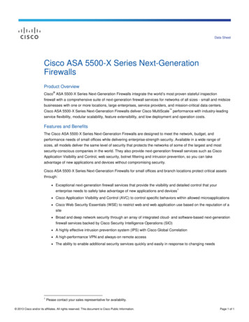
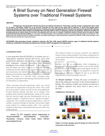
Next Generation Car Network - FlexRayFigure 1—FlexRay TopologiesFlexRay also offers many reliability features not available in CAN. Specifically, a redundantcommunication capability enables fully duplicated network configurations and schedulemonitoring by hardware. FlexRay also offers flexible configurations, with support for topologiessuch as bus, star, and hybrid types (Figure 1). Designers can configure distributed systems bycombining two or more of these topologies.Moreover, FlexRay allows both synchronous (real-time) and asynchronous data transfer to meetthe demand for various systems in vehicles. For example, a distributed control system usuallyrequires synchronous data transmission.To meet diverse communication requirements, FlexRay also provides both static and dynamiccommunication segments within each communication cycle. The static communication segmentprovides bounded latency, and the dynamic segment helps meet varying bandwidth requirementsthat can emerge at system run time. The fixed-length static segment of a FlexRay frame transfersmessages with a fixed-time-trigger method, and the dynamic segment transfers messages with aflexible, time-trigger method.In addition to operating as a single-channel system like CAN and LIN, FlexRay can operate as adual-channel system. The dual-channel option makes data available via a redundant network—avital capability for a high-reliability system.As shown in Table 1, FlexRay’s characteristics suit real-time control functions. FlexRay offers thehighest reliability among the protocols shown in the table. Figure 2 further compares networkingstandards by node cost and data rate. Table 2 gives a detailed comparison of FlexRay and CAN.3
Next Generation Car Network - FlexRayTable 1—Vehicle Network StandardsFigure 2—Comparison of Protocol Data Rates4
Next Generation Car Network - FlexRayTable 2—FlexRay and CAN Comparison#1234ITEMBaud rateNumber of channel forone nodeNetwork topologyConnection node (max.)56789Physical layerCommunicationIDData length code (DLC)Frame1011Bus line lockError status transition12Error counter13Type of errors14Oscillator1516Network managementNetwork synchronization17Bus lengthCAN1 Mbps1 chFlexRay10 Mbps2 / 1 ch (optional)Bus type16 nodes at 500 KbpsMix. of bus and star type22 nodes (bus) 22 / 64 nodes (star) 64nodes (mixed)MetalEvent triggered11 / 29 bits8 bytesData frame, remote frame, errorframe, overload frameDominant lock probableError active, error passive, busoff (software restorationpossible)Status transition counter valuefixedBit error, stuffing error, CRCerror, framing error, ACK errorCeramic and/or crystalMetal / POFTime triggered event triggered11 bits254 bytesData frameSoftwareSynchronization only withsync seg40 meters at 1 MbpsBabbling idiot (support with BG)Normal active, normal passive, haltAny status transition counter valueClock sync. errorCrystal oscillator (BG separated from CCclock)Hardware (controlled by BD and BG)Rate compensation and offsetcompensation possible22 meters (in an active star, and betweenactive starNotes: Babbling Idiot: Incorrect transfer causing damage BG: Bus guardianCC: Communication controllerBD: Bus driverFlexRay ApplicationsFlexRay targets many X-by-Wire uses in automobiles, as shown in Figure 3. Also shown in thefigure is a gateway that interfaces between FlexRay and CAN networks.5
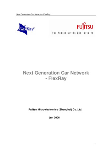
Next Generation Car Network - FlexRayFigure 3—FlexRay X-by-Wire applications with CAN ExpansionExamples of FlexRay X-by-Wire applications include:. Steering-by-Wire—Typically using electronic control unit. Anti-lock brake system (ABS)—Including vehicle stability control (VSC) andvehicle stability assist (VSA). Power train—Controlling an electronic throttle that replaces the currentmechanical system. The electronic throttle works in conjunction with existing systems such as acomputerized fuel injector, computerized variable intake control system, and computerized idlingcontrol system.FlexRay Node OperationEach FlexRay node consists of a controller part and a driver part (Figure 4). The controller partincludes a host processor and a communication controller. The driver part typically includes busdrivers and bus guardians (optional). The bus driver connects the communication controller to thebus, and the bus guardian monitors access to the bus. The host informs the bus guardian whichtime slots the communication controller has allocated. The bus guardian then allows thecommunication controller to transmit data only in these time slots and enables the bus driver. Ifthe bus guardian detects a gap in the timing, it disconnects the communication channel.6
Next Generation Car Network - FlexRayFigure 4—FlexRay NodeAs shown in Figure 5, a FlexRay node has several basic operational states:. Configuration (default config/config)—For making all kinds of initial settings,including the communication cycle and data rate. Ready—For making internal communication settings. Wakeup—For waking up a node that is not communicating. In this state, thenode sends the wakeup signal to another node, which wakes up and enables the communicationcontroller, bus driver and bus guardian. Startup—For starting clock synchronization and getting ready for communication. Normal (Active/Passive)—Communication-available state. Halt—For indicating that communication has stoppedFigure 5—FlexRay State Transitions7
Next Generation Car Network - FlexRayFlexRay nodes also have state transitions related to error handling (Figure 6). These transitionsare managed based on the value of error counters for clock synchronization and clock-correctionerrors. A clock-correction error occurs when an individual node clock differs from the FlexRaysync node clock. A FlexRay network has one or more sync nodes, which transmit sync messages.On reception of each sync message, a node compares its clock with that of the sync node clockand makes any changes needed to synchronize.Each node keeps an error count that includes the number of successive failures in clocksynchronization. A node also monitors errors regarding frame transmission/reception status,including syntax errors, content errors, bus-violation errors, and errors caused bytransmission conflicts. When a node detects any of these errors, it notifies the hostprocessor.The use of the error counter values depends on the application and is determined duringsystem design. Depending on the error condition, for example, a node can halt communication.Figure 6—Error State TransitionsFlexRay Frames and SignalsFlexRay uses a communication frame that has three segments (Figure 7).8
Next Generation Car Network - FlexRayTo transfer frames, FlexRay uses a time-trigger protocol, in contrast to CAN’s event-triggerprotocol. FlexRay’s time-trigger method enables accurate data transfers according to apredefined schedule. Additionally, the data is available on dual-redundant communicationchannels, Ach and Bch.The header segment includes the following bits:. Reserved bit—For future expansion. Payload preamble indicator—Indicates the existence of vector information in theframe’s payload segment. In a static frame, this bit indicates NWVector; in a dynamic frame, thebit indicates Message ID. Null frame indicator—Indicates whether the data frame in the payload segment isNULL. Sync frame indicator—Indicates that this is a synchronous frame. Startup frame indicator—Indicates whether the node sending the frame is thestartup node. Frame ID—Indicates the ID assigned to each node during system design (validrange: 1 to 2047). Length—Specifies the data length of the payload segment. Header CRC—Specifies the CRC calculation values of the Sync Frame Indicator,Startup Frame Indicator, Frame ID, and Length that are calculated by the host. Cycle—Indicates the cycle count of the node that transfers the frame during theframe transfer time.The frame’s payload segment includes these parts:. Data—Can be from 0 to 254 bytes. Message ID—Optional. This ID uses the first two bytes of the payload segmentfor definition and can be used as filterable data on the receiving side. Network management vector (NWVector)—Optional. This vector must be 0 to 12bytes long and common to all nodes.The frame’s trailer segment consists of CRC values specified by hardware. These CRC valueschange the seed value on the connected channel to prevent incorrect connections.FlexRay transfers frames in time slots. Figure 8 shows the organization of these time slots withregard to the FlexRay cycles.Figure 8—FlexRay Time SlotsAt the physical layer, FlexRay communicates using the differential signals BP and BM,corresponding to the voltages uBP and uBM. Four signals (Figure 9) represent various states ofthe FlexRay bus:. Idle LP: low-power state Idle: no-communication state Data 1: logical HIGH Data 0: logical LOW Note that conflicts between Data 1 and Data 0 are not allowed.9
Next Generation Car Network - FlexRayFigure 9—FlexRay Bus StatesFlexRay Solutions from Fujitsu MicroelectronicsAfter several years of refinement, the FlexRay standard is ready for system developers toleverage in next-generation vehicles. Fujitsu is supporting these efforts with a developmentsystem and a microcontroller containing FlexRay IP. Figure 10 shows the roadmap for thesedevelopments.10
Next Generation Car Network - FlexRayFigure 10—FlexRay RoadmapFujitsu’s FlexRay Evaluation Kit (MB2005-01/FlexRay-FPGA-Eva-Kit-369) includes theFPGA-based ERAY IP from Bosch. This ERAY IP implements the latest FlexRay protocol at thetime of shipment of the kit. Developers can use this kit with Fujitsu microcontrollers such as the32-bit Fujitsu FR (MB91F369 MCU) starter kit.FlexRay Node, Host controller FlexRay Node, FPGA-based (MB91F369)communication controller1Figure 11—Evaluation Kit BoardsAs illustrated in Figure 11, the starter kit includes all the functionality required for FlexRayapplication development. Specifically, the kit contains:ٛ . Host processor boarda.o 32-bit MCU MB91F369b.oTwo CAN interfaces, UART, SIOsc.o1 MB flash (on board)d.o512 Kbytes Flash (on chip)e.oOnboard monitor debuggerf.o2 MB SRAM (on board)g.o32 Kbytes RAM (on chip). FlexRay main and daughter boards with sockets for physical-layer modulesٛ . Softwarea.oDriver library for FlexRay interfaceb.oExample programٛ . Development toolsa.oSoftune Workbench on Micro CD 3.6 or later versionb.oDECOMSYS tool chain demo CDFujitsu’s new FlexRay starter kit (SK-91F467-FLEXRAY) enables designers to evaluate theFujitsu standalone FlexRay controller (MB88121A) along with the Fujitsu 32-bit flashmicrocontroller MB91F467DA. The kit includes an evaluation copy of theDECOMSYS::COMMSTACK driver library that allows easy access to the FlexRay communicationcontroller MB88121A. The kit includes:. 32-bit Flash microcontroller MB91F467DA FlexRay ASSP MB88121A Two FlexRay channels (Ch-A, Ch-B) FlexRay physical layer RS-485 on board11
Next Generation Car Network - FlexRay. FlexRay physical layer plug-in for PL modules from TZM (FT1080). 32 Mbit SRAM on-board memory. Three high-speed CAN interfaces. Three UART (RS232- or LIN-mode configurable). External bus interface on 96-pin/48-pin connectors (DIN 41612) for userapplications. Application examples on the FlexRay CD. Softune Workbench development environment on CD. DECOMSYS tool chain demo CDFigure 12—New FlexRay Starter Kit BoardFujitsu also offers a FlexRay ASSP that supports FlexRay protocol version 2.1 (ES2). This ASSPprovides the following features:. QFP64 package. 0.5-pin pitch/10 x 10 mm (M03-package). Single-supply voltage. Clock specification, 4/5/8/10 MHz crystal. Configurable parallel host interface compatible with 8-, 16-, and 32-bit MCUs.Max. frequency 33 MHz (target). Serial host interface (will be supported in the future devices)In 2006, Fujitsu will introduce two FR series 32-bit microcontrollers with an integrated FlexRaymacro. Figure 13 shows the features of the first of these MCUs, and Figure 14 shows asubsequent MCU with more on-board peripherals.12
Next Generation Car Network - FlexRayFigure 13—Fujitsu’s First FlexRay MCU (Plan)Figure 14—Fujitsu FlexRay MCU with Additional Functionality (Plan)13
Next Generation Car Network - FlexRayFor more informationFujitsu Microelectronics (Shanghai) Co., Ltd. was established in October 2003 as Fujitsu’ssemiconductor business representative in China. Headquartered in Shanghai, it has branchoffices in Beijing and Shenzhen to provide sales and service support to customers throughoutChina.Fujitsu Microelectronics (Shanghai) Co., Ltd. offers an extensive range of products frommicrocontroller, application-specific integrated circuit (ASIC), application-specific standardproduct (ASSP), system-on-chip (SoC) to system memory, that can be supplied as product orcomplete solution. With technology resource centres and ASIC design support centresstrategically located in Shanghai, Hong Kong, Shenzhen and Singapore, as well as Heavyinvestments in design and engineering capabilities and application support resources,complemented by a regional network of design partners, suppliers and distributors, FujitsuMicroelectronics (Shanghai) Co., Ltd. can readily delivers innovative and value-added solutionsand varied range of products to its target markets in China.More information, please go to http://cn.fujitsu.com/fmc/en14
control structure of automotive electronics for many years to come. FlexRay serves as the next step beyond CAN and LIN, enabling the reliable management of many more safety and comfort features. FlexRay suits X-by-Wire applications, for example. This technology backgrounder offe