Transcription
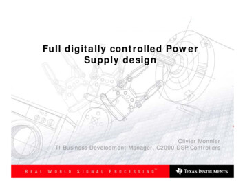
Full digitally controlled PowerSupply designOlivier MonnierTI Business Development Manager, C2000 DSP Controllers
Agenda The Digital Vision: Why DSP? Digital world: FACTS and FIGURES Digital AC/DC Rectifier challenges Software Strategy Implementation Next Steps
Agenda The Digital Vision: Why DSP? Digital world: FACTS and FIGURES Digital AC/DC Rectifier challenges Software Strategy Next Steps
The Digital Vision WhyDigital Approach for Power Supplies? WhyDSP Controllers?
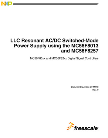
Typical Analog based AC/DC rectifierV IFilterBridgeInrush/Hot-plugControlVV IPFCVV Power controloptionalMonitorMCU(MCU ?)SupervisoryHouseKeepingCircuitsUARTAux P/STo Host
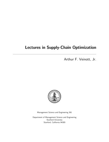
Digital approach with Single Device example for AC/DC RectifierA 1000W / 48 VF2810 DSP based2 Phase PFC-ILPhase shifted ZVS-FB200 KHz PWM (DC/DC)100 KHz PWM (PFC)
Typical ‘Control’ System On A ChipPWM(‘DAC’ U(DSP/uC/RISC) Memory(FLASH/ROM,RAM)ADCPeripheralsShown, Found On TI DSPC2000 Family Of DevicesQuad DecoderCapturei.e. BuckConverterControl Loop(i.e. PID/IIR)i.e. Vi.e. Encoderi.e. Hall Sensor
Why DSP for Power Supplies?ControllerAnalogorDigital ?PWMSensor/sAnalog Controller High bandwidthHigh resolutionEasy to understand / use“relatively’ low cost ?Component drift and aging /unstable Component tolerances Hardwired / not flexible Limited to classical control theoryonly Large parts count for complexsystems Power Elec.Digital ControllerInsensitive to environment (temp, drift, ) High reliability S/w programmable / flexible solution Precise / predictable behaviour Advanced control possible (non-linear, multivariable) Can perform multiple loops and “other”functions Bandwidth limitations (sampling loop) PWM frequency and resolution limits Numerical problems (quantisation,rounding, ) AD / DA boundary (resolution, speed, cost) CPU performance limitations System cost ?
DSP Controllers value-Proposition IntegrationFlexibilityEase of differentiationSystem cost optimization Two Main Power Supply domains targeted Industrial power supplies above 1kWMulti-phase DC/DC loops requiring synchronization
Agenda The Digital Vision: Why DSP? Digital world: FACTS and FIGURES Digital AC/DC Rectifier challenges Software Strategy Next Steps
Controller Considerations for DigitalPower Supplies Ease of Use!rotcafrSWF eaReliabilityCPU PerformancePWM resolutionLow Interrupt LatencyFast Sample RateNumeric ConsiderationsCostTechnical Support
Fully Digital System SomeFacts, Figures and Capabilities
Clock speed (MIPs) Word size (dynamic range) MAC size (16x16 / 32x32) Large on-chip SRAMs C / C ContinuallyImprovingspecs !"DAC"280x – DSPPWM"A D C "The Digital Domain ADCOutputs Buck / Boost Half bridge Full bridge / PS Multi phase ILInputs Current Voltage Temperature Resolution Linearity / Accuracy Sampling rate (speed) HV isolation
Processor capability# Inst. vs AlgorithmS/W algorithm# Instructions vs PWMPWM freq.(KHz)501002002503005007501000PWM per.(uS)20.010.05.04.03.32.01.31.0Processor 00133333500802003005313320040100150MIPS Million Instruction Per SecondclksController(2 pole / 2zero)26Controller(3 pole / 3zero)36PFC currentcommand30PFC OVP25BiQuad Filter46ZVSFB PWMdriver14PFC2PHIL PWMdriver26
Typical Power Stage Switching FrequenciesFreq. (KHz)Typ. ApplicationPower stage10 35Motor Control3 Phase Inverter50 120UPSBoost / Buck / ?80 160PFC boostAC/DC – RectifierSingle / Multi-phase Interleaved120 240DC/DC (isolated)AC/DC – RectifierH-bridge / Full-Bridge /FB-ZVS200 1000DC/DC (non-isol.)DPA-EnterpriseSingle phase Buck /Multi-phase Interleaved1 4 MHzDC/DC (non-isol.)DPA / BricksSingle phase Buck /Multi-phase InterleavedBenefits of higher frequencies1)2)3)Higher power densitySmaller magneticsLighter Power supplies4)5)Faster transient responseSmaller ripple amplitude
Agenda The Digital Vision: Why DSP? Digital world: FACTS and FIGURES Digital AC/DC Rectifier challenges Software Strategy Next Steps
Digital approach with Single Device example for AC/DC RectifierA 1000W / 48 VF2810 DSP based2 Phase PFC-ILPhase shifted ZVS-FB200 KHz PWM (DC/DC)100 KHz PWM (PFC)
Digital Control Design Steps Choose the topology for each power stage.Choose the location for the microprocessor: primary side orsecondary side.Define the gate drive circuits.Define the ADC signal conditioning circuits.Choose the configuration of the timing hardware that implementsthe PWM signals, ADC strobe and interrupt service routine (ISR)timing.Architect the firmware: time critical interrupts versus backgroundImplement the SWClosing the loop digitally offers several advantages when bringingup a system for debug.Each stage can be enabled separately.Loops can easily be run open-loop, usually by commenting out aline of code.Compensation parameters are quickly changed with a fewkeystrokes.Sophisticated diagnostics are possible, such as a circular buffers orcomplex event triggers.
Digital Control Design Steps Choose the topology for each power stage.Choose the location for the microprocessor: primary side orsecondary side.Define the gate drive circuits.Define the ADC signal conditioning circuits.Choose the configuration of the timing hardware that implementsthe PWM signals, ADC strobe and interrupt service routine (ISR)timing.Architect the firmware: time critical interrupts versus backgroundImplement the SWClosing the loop digitally offers several advantages when bringingup a system for debug.Each stage can be enabled separately.Loops can easily be run open-loop, usually by commenting out aline of code.Compensation parameters are quickly changed with a fewkeystrokes.Sophisticated diagnostics are possible, such as a circular buffers orcomplex event triggers.
Agenda The Digital Vision: Why DSP? Digital world: FACTS and FIGURES Digital AC/DC Rectifier challenges Software Strategy Next Steps
SoftwareModularity, re-useefficiency
Software - is key in Digital Power !Software playing a more significant role in AC/DC rectifier applicationsTraditionallyAnalog controlled power stageS/W role: Supervisory Monitoring Comms8 / 16 bit MCU basedDigital PowerDigitally controlled power stageS/W role: Supervisory Monitoring Comms Closed loop control16 / 32 bit DSP based“Opposing” approaches to Software development1. “Conservative approach” Strictly High level language (e.g. C / C ) Conventional function calling / parameter passing Real-time OS as needed2. “getting your performance entitlement” Combination C / ASM “flat” in-line coding non-conventional function calling / parameter passing simple single ISR structureWait for release ofappropriate devicee.g. 200-300 MIPdevice @ 5- 10Push perf. envelopeon existing devicese.g. 100-150 MIPdevices @ 5- 10
Defining “GOOD” Software Modularity – blocks with well defined inputs / outputs(“cause and effect”) Multiple instantiation of same module or function De-lineation (separation) between code and device peripheralsor target h/w i.e. use of peripheral (h/w) drivers Re-useable / Re-targetable (maximize return on investment) Efficient & high performance – code execution in minimaltime Easy to use / read / interpret / debug / modify . i.e. friendly!
1 of 2Exploring Modularity Function or object with well defined boundaries Clear relationship between inputs / outputs (“cause / effect”) Used multiple times, while maintaining a single source“Multiple Instantiation” Re-entrant (i.e. supports “nesting of itself”) “trust for now, explore / understand later”Module example 1 Single In / Single outNon-configurableNo HistoryMultiple Instantiationf(x) Sin (x)Out Sin (In)
Exploring ModularityModule example 2 Single In / Single out Configurable m, b, Constant ?or Variable ? No History Multiple Instantiation2 of 2f(x) mx bOut m.In bModule example 3 Single In / Single outNon-ConfigurableHistoryMultiple Instantiationf(x) ( xn xn-1 xn-2 xn-3 ) / 4BoxCarAvgInOutX(n)X(n-1)X(n-2)X(n-3)
Module TypesApplication Indep. /Peripheral Indep.Application Config. /Peripheral pplication Config. /Peripheral Depend.(“Peripheral Driver”)
Peripheral Drivers1 of 2Depends on: PWM frequency System clock frequencyCPU dependency only: Math / algorithms Per-Unit math (0-100%) Independent of HardwareDepends on: # ADC bits (10 / 12 ?) Unipolar, Bipolar ? Offset ?
Q-Math RepresentationFixed point format – S I . F (Sign / Integer . Fraction)Q15S.FFF FFFF FFFF FFFF- 1 N 0.99999 Q14SI.FF FFFF FFFF FFFF- 2 N 1.99999 Q13SII.F FFFF FFFF FFFF- 4 N 3.99999 Q12SIII. FFFF FFFF FFFF- 8 N 7.99999 Q0SIII IIII IIII IIII- 32,768 N 32,767Qn x Qm Qn m, e.g. Q15 x Q14 Q29SSI.F FFFF FFFF FFFF FFFF FFFF FFFF FFFF (32 bit format)SI.FF FFFF FFFF FFFF (adjusted for Q14, 16 bit format)e.g. Q15 x Q15 Q30SS.FF FFFF FFFF FFFF FFFF FFFF FFFF FFFF (32 bit format)S.FFF FFFF FFFF FFFF (adjusted for Q15, 16 bit format)
Exploring Ideas / Methods for “Good” software1. System Framework – Background loop (“C”) one ISR(“ASM”) with Time-Slicing for control loop2. In-line coding for the ISR3. Assembly Macros for the control loop modules4. Indirect or “pointer based” parameter passing / data flow5. “Signal Net” based Module connectivity Æ for theanalog guys!
Exploring Ideas / Methods1. System Framework Good choice for addressing many power systems (even complex ones)Simple to use and understandEfficient (incurs only 1 ISR context save/restore)Deterministic (all events synchronous and submultiples of ISR freq.)High degree of visibility during debug and developmentBack-ground loop (BG) C / C , large code, complex, feature rich, key customer differentiator System intelligence / personality, heavy in “if then else”Interrupt Service Routine (ISR) – Main control loop “lean and mean” in-line assembly (ASM) results in a very small footprint. Typically “Math function” type code (very few “if then else” branches or loops) Once developed, changes very little. Low maintenance burden.1 of 4
2 of 4Exploring Ideas / Methods2. In-line assembly ISRHow complex ?areFfar!octHow much code development ?How much maintenance burden ?How wasteful on memory?Number of Instructions / cycles 862502001507506005004293753003. ASM Macros – great for modularity !Modern compilers support:¾ Macro parameter passing¾ Macro variable & lable substitutionBenefits:¾ No call/return overhead (save 8 cycles/call)¾ Can easily build self contained modules (modular!)¾ Supports multiple instantiation¾ Supports “Re-entrancy”¾ Re-useable% impact per 10 .5%3.0%3.5%4.0%5.0%1501.3%1.7%2.0%2.3%2.7%3.3%
Exploring Ideas / Methods3 of 44. Pointer based parameter passing (data flow)Pseudo code0verheadmove ? , In1A(2)move ? , In1B(2)call f1(8)move ? , In2A(2)call f2(8)move Out1 , In3A (2)move Out2 , In3B (2)call f3(8)move Out3 , ?(2)Conventional approachIn1Af1Out3 f3( In3A, In3B )Out1In1BIn3Af2In2Af3In3BOut3Out2Pointer based n2APseudo code (without macros)call f1(8)call f2(8)call f3(8)*Out1*In3B*Out3Mem?Pseudo code (with macros)call f1(zero)call f2(zero)call f3(zero)
Exploring Ideas / Methods5. “Signal Net” based module connectivityInitialization time (“C”)Run time (ASM macros)// pointer & Net declarationsInt *In1A, *In1B, *Out1, *In2A,.Int Net1, Net2, Net3, Net4,.; Execute the code// “connect” the modulesIn1A &Net1; In1B &Net2; Out1 &Net5;In2A &Net3; Out2 &Net6;In3A &Net4; Out3 &Net7;In4A &Net5; In4B &Net6; In4C &Net7; Out4 &Net8;In5A &Net7; Out5 &Net9;f1f2f3f4f54 of 4
Digitally controlled AC/DC rectifier – an WF2810 DSP based2 phase interleaved PFCPhase shifted ZVS-FB200 KHz PWM (DC/DC)100 KHz PWM (PFC)PWM7PWM2PWM8T2PWMDiodeclampDiodeclampIphA PWM1VOUT(P)AIphBPrimary Side ControllerADCIOF2810DSPPWMCOMMSCAN busorSCI bus
PFC (2PHIL) Software control flow
DC-DC (ZVSFB) Software control flow
MIPS 100# TS 4S. rate 200ISRAllTS1TS2TS3TS4RateCPU Bandwidth utilization# inst / uS 100# inst / time slice 500Sampling period 5.0Function / Activity# CycPWM(KHz) 200PWM(bits) 9.0Tot. Cyc.292FW Isr200KHz Context Save / Restore32200KHz ISR Call / Return / Ack24200KHz Time slice Mgmt12Every ISR call200KHz ADCSEQ2 DRV200KHz CNTL 2P2Z 1 (V loop)14Context Save36200KHz CNTL 2P2Z 2 ( I loop)200KHz I FOLD BACK200KHz ZVSFB DRV200KHz ADCSEQ1 DRV200KHz FILT 2P2Z200KHz AC LINE RECT36ADCSEQ2 DRVCNTL 2P2Z(1)CNTL 2P2Z(2)ZVSFB DRVADCSEQ1 DRVFILT 2P2ZAC LINE RECT100KHz100KHz100KHz100KHzPFC OVPPFC ICMDCNTL 2P2Z 4 (I loop)PFC2PHIL DRV2530362611750KHz50KHz100 Hz50KHz1KHzBOXCAR AVG 1BOXCAR AVG 2PFC ISHAREExecution Pre-scaler(1:50)CNTL 2P2Z 3 (V loop)4242151036145100KHz100KHz100KHz100KHzPFC OVPPFC ICMDCNTL 2P2Z 4 (I loop)PFC2PHIL DRV2530362611750KHz50KHzFILT BIQUADINV SQR4678124% Util58%251457357% Util82%Time Slice mgr#Cyc. Rem.91% Util87%#Cyc. Rem.63% Util82%#Cyc. Rem.91% Util83%50 KHz50 KHz50 KHzFunction / ActivityComms Supervisory Soft-Start Other ?SLEW LIMIT 1SLEW LIMIT 2# inst.400Tot.Cyc.434TS2TS3TS4PFC OVPPFC ICMDCNTL 2P2Z(4)PFC2PHIL DRVBOXCAR AVG(1)BOXCAR AVG(2)PFC ISHAREExecPS(1:50)CNTL 2P2Z(3)PFC OVPPFC ICMDCNTL 2P2Z(4)PFC2PHIL DRVFILT BIQUADINV SQRStatsInt AckContext restore1717% ISR utilization Spare ISR MIPS BG loop rate (KHz) / (uS) 87%12.629.034.450 KHzTS1#Cyc. Rem.84BG200 KHzStatsReturn
Experimental results
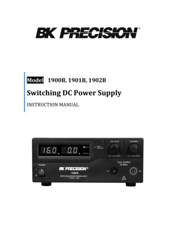
Interleaved Boost PFCPhase Acurrent Phase Bcurrent2 Interleaved boost convertersMOSFET Rds,on current senseExcellent current sharing between modules
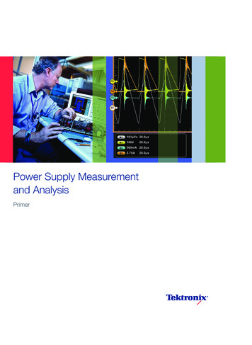
Phase Shifted Full Bridge DC-DC Phased-Shifted Full-Bridge operates off PFC boostVds of Q6/Q7
Zero Voltage Switching ZVS of the PSFBBottom trace is Vgs top trace is Vds.Vds falls to 0V before Vgs turns on MOSFET
DSP Controlled PFC ControllerInput Current,Po 860WInput Current,Po 580W
DSP Controlled PFC ControllerPFC MOSFETsDrain-Source VoltagesDC Bus VoltageTransient Response,Step load 250W
DC/DC Stage Transient Response Load step 230 W (580W Æ 350W Æ 580W)Voltage deviation 1.6% @ 48VSettling time to within 1% 250uS
Digital Rectifier Summary Digital control allows: Sophisticated fault detection. Supports wide voltage and load range (DCM and CCM). Soft start and bring up sequence completelyprogrammable. Long timeframe load sharing and deadband control loopseasily implemented. Diagnostic data logging. Single processor for communication and control. Performancedesigns.very similar to best analog
Agenda The Digital Vision: Why DSP? Digital world: FACTS and FIGURES Digital AC/DC Rectifier challenges Software Strategy Next Steps
Real-Time debug2 of 2 RTDebug is a Non-intrusive debug scheme supportedvia on-chip H/W (utilizes spare / dead cycles in CPU buses) Allows user full interaction while application runsun-disturbed (at speed) Can interrogate / modify any memory, register, variable, .etc Supports Single step / Break point in back-ground codewhile ISR (time critical loops PWM) continues to run at speed. Clock / cycle profiling allows time critical code analysis.
Agenda The Digital Vision: Why DSP? Digital world: FACTS and FIGURES Digital AC/DC Rectifier challenges Software Strategy Implementation Next Steps
C2000TM 08F2809C2802HigherPerformanceC281xTM 150 MIPS 128-256 KB 12.5 MSPS ADCC2810FutureLowerCostF2812DPSC280xTM 100 MIPS 32-256 KB 150ps PWM 7 pin-compatibledevicesC240xTM10 DevicesLF/C240xA 40 MIPS 16-64 KB 10-bit ADCIntegrationF FlashC Custom ROMR RAM only
How to get Started today? F2812 eZdsp & R2812 eZdsp developer’s kit ( 495) F2808 eZdsp kit in 1Q05 ( 495)TMToolsSoftwareTrainingand Support Code Composer StudioTM IDE for C2000TM ( 495 today) Application specific libraries Math functions Communications drivers Pre-bundled system solutions Control developers seminar DMC workshop One-day technical introduction to C28x Multi-day get started developing C28x workshopTMTMHighPerformanceAnalogThird PartyNetworkNumerous data converter and power managementproducts designed for motor control Development boards and emulation tools Large consultant network Increasing range of application software
TI Provides the Systems Expertise, Silicon, Software andSupport for Control ApplicationsSystems ExpertiseSiliconSoftwareDigital Software )Position/SpeedFeedbackTMS320C2000SupportWeb castsWorkshopsKnowledgeBaseApplication notesEEPromKalman FilterPrecision PIDFilter LibFieldOrientedControlSPIEV(PWM)CAN SCI-A/BPeripheralDrivers“IQmath”DSP/BIOSTI PowerManagementFoundation SoftwareCANNetworkPC TestEquipment
Modular Software Development for DigitalControl DACdrvReal-Time MonitorRealTime DSP/BIOS C24xTMC28xTMThird PartiesQEPPositiondrvS/W Test Benches (STB)Modular Libraries (DMC, FFT, Math, Filters etc)Hardware ToolsApplication Specific Systems (ACI, BLDC, PID cntl )Code Composer Studio All Modules Available in C/C ti.com/c2000sigproclib Reduces timeto market ProvidesreuseablesoftwareGets youtherequickly
The Foundation: Software LibrariesMotor Control Specific SW ModulesForward and Inverse Clarke/Park Transforms,, BLDC Specific PWM Drivers, Leg CurrentMeasurement Drivers, BLDC Commutation triggers, ACI Speed and Rotor PositionEstimators, PID Controllers, Extended Precision PID Controllers.Peripheral & Communication DriversSCI (UART) Packet Driver, Virtual SPI Drivers, Virtual I2C Drivers, Serial EEPROM Drivers,GPIO Driver.Fixed Point Trigonometric and Log RoutinesFixed Point Sine, Cosine, Tangent routines, Square Root, Logarithm Functions. Reciprocalcalculation.IQ Math 32-Bit Virtual Floating Point LibraryMultiply, Divide, Multiply with Rounding, Multiply with Rounding and Saturation, SquareRoot, Sine and Cosine, routines.Signal Processing FunctionsFIR (Generic order), FIR (10th order), FIR(20th order), FIR using circular buffers. 128, 256,and 512 point complex and real FFTs.Signal Generator FunctionsSinewave generators, Ramp Generators, Trapezoidal Profile generatorsPower Conversion Related FunctionsRMS computation, real power and apparent power computation, THD computation, PFCcontrollers.
Digital Power Modules – Some ExamplesSymbolDescr.Controller,2 pole / 2 zero# r.T2PWMHWT4PWMAdj# CyclesPFC 2-phaseInterleavedPWMs/w driver26Zero VoltageSwitchedFull BridgePWMs/w driver14Analog /Digital conv.Sequencers/w driver57Multi-phase3InterleavedPWMs/w 8rlegdbADC A030ADCSEQ1DRVADCHWADC A1ADC A2ADC A3ADC A4Rslt[0:5]Slew rateLimiterfunctionPFC overvoltagemonitorADC PWM3AEPWM3B
S/W driver module – ZVSFB1 of 2
S/W driver module – PFC2PHILPFC2PHILDRVNet1DutyNet2AdjEVHWT2PWMT4PWM1 of 2
Digital Power Supplies: collaterals First version of the Digital Power Supply Library has beenreleased Check out: www.ti.com/c2000appsw Digital Power Theory application note: SPRAAB3
Graphical Ease of Development Use high-level, predebugged blocks Support simulation ofcontroller at block level onPC Allow mouse probe of everyinput and output to displayvalues at any instant Debug block-level simulationon PC
Hardware-in-the-Loop Pure simulation plus DSP-in-loop simulation and block level monitoring givesrapid feedback of controller responseVisSim on PCExternalHardwareC2000TMDSPPeripheralInput BlocksPeripheralOutput Blocks(I/OOnly)VisSim block dBlocksTest DSP based controller against virtual plant on PC using JTAG HotLink Inject plant failure modes to test controller response High/Low watermark on fixed-point blocks gives numerical “headroom” safety factor Interactive DSP utilization gives continuous CPU load factor Interactively Change DSP controller gains from VisSim and plot DSP response.
Conclusion Digital Power is the future One of the Traditional Fear Factors industry is SW complexity TI is enabling Digital Power with the Digital Power Supply Library 28x has the right set of peripherals for Digital Power Supply Tools, Documentation are in place to start today TI can support for a complete design with Analog and Digitalproducts
Thank youVisit usStand 134, Hall 12Meet our experts anddiscover our expandedrange of productsThird parties exhibiting at TI booth:
Analog controlled power stage S/W role: Supervisory Monitoring Comms 8 / 16 bit MCU based Digital Power Digitally controlled power stage S/W role: Supervisory Monitoring Comms Closed loop control 16 / 32 bit DSP based “Opposing” approaches to Software development 1. “Conse