Transcription
Structural DesignGuide
TABLE OF CONTENTS1.Introduction & Scope of Manual-page 12.Standards Used and Other References-page 23.Background - TR019: calculation models forprefabricated wood based loadbearing stressedskin panels for use in roofs.-page 34.Material Properties-page 45.Loading on structural SIP Panel elements andassociated deflections (for SLS)-page 66.SIP Roof Panels-page 97.Design of SIP roof panels (single span) withouttimber “spline” reinforcement.-page 9Design of SIP roof panels (single span) withtimber “spline” reinforcement.-page 14Design of SIP wall panels (single span) withouttimber “spline” reinforcement.-page 1610.Lintels-page 1911.Racking Resistance-page 198.9.Annex A:SIP Roof Load-Span Tables-page 21Annex B:SIP Wall Load-Span Tables-page 36Annex CGlued SIP-Lintels Tables-page 38Sips Eco Panels Design Guide
1.Introduction & Scope of Manual1.1This Design Manual has been prepared by Tim Kelly Consulting Engineers Ltd. onbehalf of Sips Eco Panels as a design aid to Structural Engineers in the structuraldesign of their Structural Insulated Panels (heretofore known as “SIP panels”). It isexpected that the Structural Engineers shall have a good working knowledge ofEurocode 0, Eurocode 1 (parts 1, 3 & 4) and Eurocode 5. It is further assumed thatthe Structural Engineer is experienced in timber frame / SIP frame design.1.2Sips Eco Panels Ltd's SIP panels are a composite, sandwich panel manufactured bygluing outer skins of OSB/3 to expanded polystyrene insulation (of minimum gradeEPS90).1.4The Sips Eco Panels section depths that form the integral part of this document are119mm, 144mm, 169mm, 194mm and 219mm. This should not exclude other sizesbeing added in the future as the calculation methods described within can be readilyadapted for any combination of thickness of OSB skins and EPS insulation.1.5The SIP panels described within are currently limited to roof and wall elements.Glued SIP lintels are also designed and incorporated as part of the wall design.The “SIP structure” will also include some or all of the following elements:1.5.1. Solid timber ceiling ties.1.5.2Internal solid timber stud walls (studs typically at 600mm or 400mm crs.) as perstructural engineers design and specification.1.5.3. Solid timber or engineered timber floor joists (engineered timber floor joists aretypically proprietary I-joists or open web joists) which are seated on the load-bearingSIP external wall panels and the solid timber internal load-bearing stud wall panels.There is typically a rimbeam running around perimeter of floor.Joists may also be hung from side of SIP panels using proprietary joist hangers suchas Simpson Strong-tie IUQ and HIUQ hangers or similar. The joist hangers must beallowed by the proprietary hanger manufacturer for this purpose.1.5.4. Solid timber, engineered timber or steel floor beams and purlins which shall bedesigned to adequately resist the applied loading as per normal structural designprinciples.As items described in 1.5.1 to 1.5.4 are not limited to SIP structure and their design isstandard and very well described in numerous publications, this document shall,henceforth, limit itself to structural design specifically relating to the SIP panels.1.6Previously, Sips Eco Panels Structural Design Guidance was based primarily on testresults which were used to produce tables and prescriptive design guides to theprinciples of BS 5268 and associated British Standards. The previous design guideswere, thus, limited to the section sizes tested and to use of BS5268. Therefore thedesign guide wasn’t “future-proof” as it didn’t allow for differing panel thicknesses orchanging of standards to Eurocodes. There is nothing stopping a designer fromcontinuing to use the older design guides as long as designs to British Standards ispermitted and assuming that correct design principles are being applied. Principlessuch as shear deflection and time dependent designs are critical. The use of tableswhich only state “short-term” loading are confusing for an inexperienced designer.1Sips Eco Panels Design Guide
The main objectives of this design guide are as follows:1.6.1To allow for a design methodology based, to a much greater extent, on design from1st principles. This allows for a greater design flexibility in the use of materials andsection depths.1.6.2To produce a design guide and accompanying tables to provide a basis for design ofthe Sips Eco Panels to Eurocode design. Note that all British Standards conflictingwith Eurocode have now been withdrawn (although it is understood that until 2016 itis permitted to use either Eurocodes or British Standards. These designs should, asalways, be carried out by a Structural Engineer experienced in the design of SIPpanels.1.6.3To include Glued SIP lintel table to the Structural Design Manual (Annex C).2.Standards Used and Other References2.1BS EN 1990: 2002 A1: 20062.2BS EN 1991: 2002 A4: 2004Action on Structures: Part 1-1:General actions – densities, self-weight, imposed loads on Buildings.2.3BS EN 1991-1-3: 2003Snow loads.-Actions on Structures: Part 1-3:2.4BS EN 1991-1-4:2005 A1: 2010Wind loads.-Actions on Structures: Part 1-4:2.5BS EN 1995-1-1:2004 A1:2008Design of Timber Structures: Part1-1: General -Common rules and rules for Buildings.2.6BS EN 300: 2006Definitions, Classifications and Specifications.2.7BS EN 13163Thermal insulation products forbuildings. Factory made expanded polystyrene (EPS) products: Specification.2.8BS EN 301:2006Adhesives, phenolic andaminoplastic, for loading bearing timber structures. Classification and performancerequirements2.9BS EN 12369-1: 2001Wood-based Panels –Characteristic Value for Structural Design – OSB, particleboard and fibreboards.2.10BS EN 338: 2009Classes.2--Basis for Structural Design.Oriented Strand Boards (OSB) –Structural Timber: StrengthSips Eco Panels Design Guide
2.11Non-standard References2.11.1 TR019 EOTA Technical Report: calculation models for prefabricated woodbased loadbearing stressed skin panels for use in roofs.2.11.2 Manual for the Design of Timber Building Structures to Eurocode 5 by TRADA andI.Struct.E.2.11.3 Structural design to Eurocode 5 by Jack Porteous and Abdy Kermani.2.11.4 Sips Eco Panels 119, 169, 194, 219mm Structural Insulated Panels (SIPs): DesignTechnical Report for Third Party approval to Eurocode by Milner Associates.2.11.5 Lightweight Sandwich Construction by JM Davies.3.Background - TR019: calculation models for prefabricated wood basedloadbearing stressed skin panels for use in roofs.3.1There are several types of stressed skin panels presented in TR019. In relation toSIP panel design, there are 2 of relevance:3.1.1Type A Stressed skin panels, closed box type double skin, without woodenribs, with load-bearing insulation (i.e. SIP panels with SIP splines only at panel /panel connection).3.1.2Type B1 Stressed skin panels, closed box type double skin, with wooden ribsand load-bearing insulation (although the design methodology for SIP panels withsplines ignores the effect of the insulation in this case. Longer spans may be possiblein the future with clarity on the TR019 design method of sandwich panels withwooden ribs and load-bearing insulation).3.2In all cases, it is critical to the design that the grain / strand direction of timber / OSBis parallel to the span direction.3.3Although TR019 is primarily for use for roof panels, the principles of TR019 andEN1995-1-1 can be used to design SIP wall panels as will be described in furtherdetail in Section 9.3.4Shear deflection: Due to the relatively low shear modulus (Gc) of the expandedpolystyrene core (which transfers shear loads within the sandwich panel), the sheardeflections in SIP panel design are significant and must be calculated for both theinstantaneous deflection and final deflection stages.3.5Creep: The deformation modification factor, kdef for both OSB and ExpandedPolystyrene (EPS) are high and hence the additional deflection due to creep overtime is very often critical. The effect of creep must be applied to both bending andshear deflections.In addition, the ultimate limit state design checks (bending, shear, etc) must becarried out for both the instantaneous response of the material to the applied actionsand the final (re-distributed) response. These are based on the reduced moduli ofelasticity and shear moduli of the outer skin OSB (typically in Service class (SC) 2),the Inner skin OSB (typically in Service Class (SC) 1) and the EPS core.3Sips Eco Panels Design Guide
Note that the kdef value of OSB in SC1 (1.5) and SC2 (2.25) differ. This means that,even when the OSB for inner and outer skins are identical, the neutral axis of the SIPpanel at the final (re-distributed) response stage shall not be at mid-depth of the SIPpanel.3.6TR019 is based on the Kreuzinger model which shall be described in greater detail inSection 7.4.Material Properties4.1Outer and inner wood panel skins - These are both 11mm OSB/3 which shall be incompliance with BS EN 300 and BS EN 12369-1. Both skins are glued to theexpanded polystyrene core in a quality controlled factory process (whereby OSB/EPS samples are regularly tested to ensure failure does not occur along adhesivebond-line - samples taken as required to comply with CATG certification).Material Properties of OSB3 have been used as described in Table 1 below, whichrepresents the minimum permitted strength and stiffness values (based on BS EN12369-1: 2001). Only values of relevance to the design of SIP roof panels, SIP wallpanels and glued SIP lintel have been stated.Table 1:Properties and Density Values for 11mm OSB outer and inner boardsStrength / Stiffness / DensityPropertyEC5 notationValues and unitsCharacteristic tension stressft,0,k9.4N/mm2Characteristic compression stressFc,0,k15.4N/mm2Characteristic panel shear stressfv,0,k6.8N/mm2Characteristic rolling shear stressfr,k (or fv,r,k)1.0N/mm2Characteristic flexural stressfm,0,kCharacteristic densityρkMean modulus of Elasticity (MOE)Et,0,mean & Ec,0,mean3800N/mm2Mean Panel modulus of rigidity ed on Table 3.2 of EN1995-1-1, the values for kdef (permanent load deformationmodification factor) is as follows:4.1.1OSB/3 in Service Class 1 environment 1.5.4.1.2OSB/3 in Service Class 2 environment 2.25.4Sips Eco Panels Design Guide
4.2Properties of the Expanded Polystyrene (EPS) core:4.2.1The core material comprises of expanded polystyrene and is assumed to be ofStrength Class EPS90 or better. The expanded polystyrene should be laid onto theOSB/3 lower layer (during production) in one piece with a 45mm rebate around theedges to allow for placement of SIP or timber splines as required by the design.In cases where it is not possible to place the EPS layer in one piece, the pieces mustbe glued together ensuring full glue spread between the abutting pieces.It should be verified by tensile testing that failure is away from the bond-line, i.e. theglue has greater strength than the EPS.Material properties of EPS90 have been used in the design as stated in Table 1below.Table 2:Expanded polystyrene EPS90 (min. strength class) PropertiesPropertynotationValues and unitsCharacteristic panel shear stressfv, kMean Core modulus of rigidity (shearmodulus)Gc,mean2.48N/mm2 (b)Deformation modification factorkdef,perm3.0 (c)kdef,med1.0 (d)kdef,short0.0 (e)0.0675N/mm2 (a)(permanent and long-term loads)Deformation modification factor(medium-term loads)Deformation modification factor(short-term and inst.-term loads)Characteristic density of coreρk18.75kg/m3 (f)Table Notes:(a)Characteristic panel shear stress is based on interpolation from table in SectionE3.1.1 of TR019.(b)Mean core modulus of rigidity is based on interpolation from table in Section E3.1.1of TR019.(c)Deformation modification factor, kdef,perm for permanent and long-term loads is basedon previous Sips Eco Panels test data and is the value given in previous qualityscheme.(d)Deformation modification factor, kdef.med for medium-term loads is based oncalculation (kdef,perm * ψ2), where ψ2 0.3 for floor imposed loading.5Sips Eco Panels Design Guide
(e)Deformation modification factor, kdef.short for short and instantaneous-term loads isbased on calculation (kdef,perm * ψ2), where ψ2 0.0 for roof imposed, snow and windloads.4.3Properties of the Timber Splines and Rails:The characteristic strength and stiffness properties and the densities and deformationmodification factors for the range of timber grades are as per BS EN 338: 2009 andEN 1995-1-1.These are widely documented and should be well known to engineers using thisguide. Hence it is not considered necessary to repeat them here.4.4Adhesives4.1The adhesive used for fixing of OSB to EPS90 (or better) shall have greater strengththat the EPS. This shall be proven at regular intervals, in accordance with CATGcertification requirements, by tensile testing which must demonstrate that failureoccurs in the EPS and not within the bond-line.4.2The glue used to fix the OSB to the top and bottom timber flanges in the Glued-SIPsLintels shall be in accordance with BS EN 301: 2006 and shall be a structuraladhesive of Type 1 or 2.4.3All gluing shall be done in a factory environment and the glue laid in strict compliancewith the glue manufacturers requirements.5.Loading on structural SIP panel elements and associated deflections (for SLS)5.1SIP panels will typically be subjected to some or all of the following loads:5.1.1Gravity loading: This is a combination of permanent (Gk) and variable loads (Qk)applied to the structure based on loads to EN1991 loads (or BS6399 if continuing touse British Standards if / where permitted). There can be several different types ofvariable loads, each with different load durations.Uniformly distributed loads for the SIP panels themselves can be calculated from thecombined: (thickness of 2 no. outer skins in metres x 550 thickness of core inmetres x 19) to give a self-weight load in kg/m2. Clearly if timber ribs / splines areused these should be additional to this based on mean timber density for the timbergrade used.5.1.2Wind Loads perpendicular to plane of SIP panels, i.e. those loads resulting incompressive stresses on one OSB skin and tensile forces on the other skin. Thisload is also a type of variable load, qk,wind.5.1.3Wind loads applied in the plane of the SIP panels, i.e. applying racking / shear forcesto the SIP panels.5.2Load Cases:6Sips Eco Panels Design Guide
5.2.1The various loads are applied to the structure in the form of a set of load-cases whichare separately applied in accordance with EN 1990. There are often several loadcases for the ultimate limit state and several load cases for the serviceability limitstate.5.2.2Ultimate limit state load cases:The basic equation, from which several load cases can be defined at ultimate limitstate is: ƔG,j.Gk,j ƔQ,1. Qk,1 ƔQ,i. ψ0,i . Qk,ij 1i 1whereGk and Qk Characteristic permanent and variable actions (loads) respectively.ƔG ULS partial load factor for permanent loads, i.e. 1.35.ƔQ ULS partial load factor for variable loads, i.e. 1.5.ψ0 Factor for combination value of a variable action (See table A1.1 of EN 1990or table in UK NA if different). For domestic floor load and for imposed roofload, the value of ψ0 0.7, for snow load and for wind load,ψ0 0.5.On a SIP roof panel, there would be typically 4 load-cases with each case having adifferent “leading” variable load, i.e. roof imposed load, snow load, man point loadand wind load (for the purposes of the Load-span tables within this document, a roofimposed load only has been considered, there will be cases where the snow load iscritical and the design engineer must consider the possibility of snow load beingmore critical than roof imposed load in their design.On a SIP wall panel, there can be several other load-cases to consider due to thepossibility of floor imposed loads, etc.5.2.3Serviceability limit state load cases:In relation to SIP panel design of roof and walls only, limiting deflection to acceptablelimits is the sole serviceability limit state criteria (vibration not a consideration forthese elements). There are 2 parts to the deflection of a SIP panel, i.e. instantaneousdeflection, uinst and creep deflection, ucreep. These are added together to obtain thefinal deflection, ufin.5.2.3.1 The basic equation, from which several load cases can be defined for instantaneousdeflection is: Gk,j Qk,1 ψ0,i . Qk,ij 1(instantaneous deflection loadcases)i 1This is the basis for similar loadcases as set-up for the ultimate limit case, except thepartial load factors are omitted for the serviceability limit state cases.7Sips Eco Panels Design Guide
5.2.3.2 The basic equation, from which the load case can be defined for creep deflection is: Gk,j ψ2,i . Qk,ij 1(creep deflection loadcase)i 0ψ2 are the factors for the quasi-permanent value of variable actions (Table A1.1 ofEN1990).For all of the common roof applied variable loads, i.e. roof imposed, snow and wind, 0 and therefore the creep deflection for roof loads is based on permanent (andinclude long-term loads such as storage also) loads only.For walls, the main load causing deflection, i.e. wind load normal to the SIPs panel,has a “0” creep associated with it but there will be a creep deflection resulting fromaxial load induced deflections, i.e. from permanent, long-term and medium-termloads.N.B. If designing using BS 5268, note that rafter imposed and snow loads aremedium-term loads (short-term to Eurocodes) and floor loads are long-term loads(medium-term in Eurocodes). Therefore there may be a creep deflection to considerfrom roof panels and a larger creep deflection to consider from floor, snow and rafterimposed loads than would be case for Eurocode design.5.3Deflections:5.3.1Due to the large shear deflections and the large creep deflections, this is often thelimiting criteria for SIPs. The final deflections are best calculated as follows for SIPpanels:ufin, ufin,G ufin,Q,1 ufin,Qiwhere i 1 for final part of equation.ufin,G uinst,G (1 kdef)(final defl. resulting from perm. action)ufin,Q,1 uinst,Q,1 (1 ψ2,1. kdef)(final defl. resulting from lead variableaction).ufin,Q,i uinst,Q,i (ψ0,i ψ2,i. kdef)(final defl. resulting from lead variableaction;i 1 (i.e. secondary variable actions).For SIP roof panels to Eurocode designs (for sites 1000m above sea level), thissimplifies to:ufin uinst,G (1 kdef) uinst,Q,1 uinst,Q,i . ψ0,iSIP wall panels, on the other hand, will generally require a full deflection derivationas ψ2 will not be equal to 0 for all wall applied loads.The instantaneous deflection, uinst is comprised of both bending and shear deflectioncomponents. The final deflection equations therefore account for both also being amultiplier of the instantaneous deflection.Deflection limits are now subject to agreement between the designer and the client(or his representative)8Sips Eco Panels Design Guide
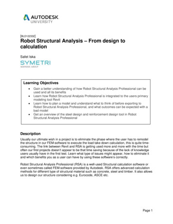
For the load span tables in Annex A, B and C, the following deflection limits havebeen assumed:5.3.1.1.Instantaneous deflection: L/350.5.3.1.2.Final deflection:L/250.This may be relaxed if there are no brittle finishes to ceiling. The client may alsodictate more onerous deflection limits for certain elements.6.SIP Roof Panels6.1Roof of SIP panel buildings can be from loose rafters, ceiling joists,prefabricated roof trusses or SIP roof panels. SIP roof panels are usuallysupported on a ridge purlin, possibly with intermediate purlins and on wall (orfloor member) at eaves level.6.2Generally, supports should downstand below SIP roof panels, with the SIPpanel supported on triangular wedges which are connected down tosupporting structure. The connections from the SIP panel to the wedge andthe wedge down to the supports must be able to fully resist the “sliding” forcedue to the “in-plane component of the gravity roof load (permanent andvariable loads) along the slope of the roof, i.e. panel to wedge screws inshear. They must also resist the worst wind load-case which is causing anuplift force on the roof, perpendicular to the plane of the roof, i.e. panel towedge screws in tension.6.3A SIP roof, without additional bracing, will generally provide adequate roofdiaphragm action.6.4The design of a SIP roof requires the determination of loads perpendicular tothe plane of the panel. The length of the span is the slope length.6.5The use of SIP panels in flat roofs is permitted, however the designer shouldbe aware of the very significant risk of failure (serviceability limit state andpossibly ultimate limit state in extreme cases) if the roof is subjected to waterponding due to inadequate falls. This is particularly high risk for SIP panelsdue to the additional long-term load from the water, which would not havebeen accounted for in the creep deflection calculation (as no variable loadrelated creep is accounted for in roofs (see section 5.2.3.2)).7Design of SIP roof panels (single span) without timber “spline”reinforcement.The following steps should be taken to verify the design of a SIP roof panel (the useof a computerised calculation, such as spreadsheet or similar is stronglyrecommended due to the complexity of the design calculations for these compositepanels). The design is based on TR019 and the structural engineer should becomefamiliar with this document before attempting to apply a design to SIPs.97.1Calculate the structural span on slope for the SIP panel. This is the span tobe used in the design.7.2.Resolve the dead (GDL) and variable loads (QIL) in the load diagram shownbelow so that the vector components of these loads acting perpendicular toSips Eco Panels Design Guide
the roof are derived. The wind load, QWL shall already be acting perpendicularto the plane of the roof. See Figure 1 for forces to be resolved.In figure 1 where:GDL dead (permanent) loadQIL variable gravity loads (variouscombinations of roof imposed, snow, man pointas laid out in section 5.2).QWL variable wind load.QILQWLGDLαLplanFigure 17.3.Calculate the unfactored maximum forces i.e. moment and shear for the various loaddurations, i.e. permanent (include long-term if applicable), short-term (worst case forman load / roof imposed / snow load) and instantaneous (wind load).These calculated forces can then be factored using the partial load factors, ƔG and ƔQin previously stated combinations in which the appropriate ψ0 factors (as per Section5.2).7.4State the geometric and material properties of the 3 layers (due to differences in kdefbetween inner and outer OSB skins) similar to that shown on the page overleafState the relevant material types, thicknesses, service classes and strength andstiffness properties (as well as densities and calculated relevant areas) for each ofthe 3 layers.10Sips Eco Panels Design Guide
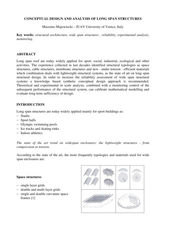
Figure 27.5Determine the Steiner bending stiffness and shear stiffness of virtual beam B for theinstantaneous response period:This is based on calculation of the neutral axis position as shown overleaf (diagram isalso appropriate for derivation of neutral axis based on final response stiffnesses).Note that the neutral axis will be central at the instantaneous response check whereOSB skins are the same but will not be centred at final response check due to theouter skin stiffness being lower than that of the inner skin due to differing kdef values(as outer skin in SC2 and inner skin in SC1).11Sips Eco Panels Design Guide
7.6Ultimate Limit State design checks at the instantaneous response (these checks tobe made for all relevant load duration cases).7.6.1Calculate the compression stress in the upper OSB layer and the tensile strength inthe lower OSB layer resulting from the applied ULS moment on the SIP panel asdescribed in C2.1.3 of TR019. Design to ensure that these are less than theallowable design compression stress (and tension stresses) of the top (and bottom)OSB layers respectively:i.e. verify that σc,d,1 fc,0,d for compression andσt,d,1 ft,0,d for tension.fc,0,d fc,0,k x kmod / ƔMwhere:and ft,0,d ft,0,k x kmod / ƔMkmod is modification factor for duration ofload and moisture content where kmodfor various timber members and woodbased panels are defined in Table 3.1 ofBS EN 1995.ƔM material modification factor asdefined Table 2.3 of BS EN 1995.7.6.2Carry out shear checks for each layer as well as the interface between the layers asper C2.1.4 and C2.1.5 of TR019. The designer should verify that the maximumapplied design shear stress be less than the permissible design shear stress of theEPS90 (or better) core.7.6.3The local design compressive stress in the EPS90 core should be checked at eachsupport in accordance with C2.1.6 of TR019.Verify:7.7σc,d,2 Rd / Aeffwhere the notation is as described in C2.1.6.Ultimate limit state design after internal force re-distribution (final response):At final response stage, the stresses within the layers will be re-distributed due to thechanges in relative bending and shear stiffnesses of the 3 layers (primarily due to thefact that the outer OSB layer is in service class 2 environment and is subject to ahigher kdef than the Service class 1 inner OSB layer). The different stiffnesses ofeach layer is due to reduced Emean and Gmean values for the layer based on thecalculation for each layer:12Sips Eco Panels Design Guide
Emean,fin Emean,i / (1 ψ2. kdef)andGmean,fin Gmean / (1 ψ2 . kdef).(for roof loads, ψ2 1 for permanent / long-term loads and 0 for short andinstantaneous loads. For wall panel designs, derivation may be required for bothEmean,fin ,perm and Emean,fin,med as well as Gmean,fin,perm and Gmean,fin,med to check at mediumterm response also)Verify that the design compression, tension and shear stresses, based on the finalresponse re-distribution of stresses are less than the design resistance stresses(similar to checks carried out for instantaneous response as described in 6.4.6.1 and6.4.6.2 above).7.8Verification of serviceability limit states:7.8.1The deflection should first be calculated based on instant loading of the panel. Thisshall be based on the equations stated in Section 5.3 of this document and mustinclude a calculation of shear deflection in addition to bending deflection.From Annex A (A.2) of TR019, the instantaneous deflection shall be calculated basedon the below equation for each of the instantaneous deflections from permanent,lead variable and secondary variable loads:uinst 5 w L4 384 (EI)B,instw L28 (GA)B,instSee equation above and equations in Section 5.3 for calculation of uinst,total andcalculation of ufin,total.7.9For SIP roof panel designs it is critical that the permanent (and long-term ifapplicable) loads are correctly applied as these will have a significant effect on thecritical final deflection calculation.It is also critical that shear deflections are accounted for and also that the effect ofcreep is fully calculated. The shear deflection is often much larger than the bendingdeflection while the creep deflection component is often larger in magnitude to theinitial deflection, i.e. the final deflection is 2 x initial deflection.7.10Roof load span tables in Annex A are based on the calculation methodologydescribed in this section (see also load-span table notes in Annex A for guidance onusing tables).7.11The principles of the design methodology set out above, based on TR019 andEN1995-1-1 could be used to produce a design calculation to BS 5268 if consideredappropriate by the designer. This would be based on the working stress principle oftimber design to the British Standards.Alternatively, previously produced design tables based on loading can be used todetermine allowable spans for SIP roof panels. These are based on short-termloaded tests and it is critical that due account is taken of creep deflection and alsoreduced permissible stress resistances for permanent / long-term portion of load.Using the spans as stated in these test-based tables, without accounting for theseitems, may yield unsafe designs!13Sips Eco Panels Design Guide
7.12SIP splines are used to connect adjacent SIP panels together. These should not beconsidered structurally in the design of the SIP roof panel.7.13The designers first preference, where possible, should always be to place purlins, etcat centres to allow for unreinforced splines as this avoids repeat thermal bridges. Dueto the constraints of some projects this is not always possible and in these cases atimber spline reinforced SIPs panel is required as described below in section 8.8.Design of SIP roof panels (single span) with timber “spline” reinforcement.8.1Timber splines are used to stiffen / strengthen SIP roof and wall panels. They areplaced within the 45mm wide rebate at each end of the 1.2m wide SIP panels.Therefore there are 2 no. 45mm timber splines at 1.2m crs. The depth of the timbersplines is: depth of SIP panel – 11mm upper OSB – 11mm lower OSB – 2mm, i.e. a144mm deep SIP panel will have a 120mm deep timber spline, etc, etc.The OSB connects to the timber splines with 3.5 x 50mm screws @ 150mm crs. (intoeach 45mm wide timber member). There are 2 splines within a 1.2m panel so it isappropriate to design for a 1.2m panel with 90mm wide timber splines screwed @75mm crs. (2 no. screws @ 150mm crs.).SIP roof panel with reinforced timber splines achieve longer spans, as demonstratedwithin load-span table in Annex A. On rare occasions the roof spans may dictate anaddition full depth (of SIPs panel) timber spline between the “rebated” timber splines.8.2The design of a SIP roof panel with timber splines can be undertaken as follows:8.2.1The loads are calculated in the same manner as for the unreinforced SIP roof panel(Section 6.4.2) except that design should allow for a 1200mm wide panel and hence1200mm wide loading.8.2.2Additionally, the moments and shear forces are calculated similarly as described inSection 6.4.3.
2.11.2 Manual for the Design of Timber Building Structures to Eurocode 5 by TRADA and I.Struct.E . 2.11.3 Structural design to Eurocode 5 by Jack Porteous and Abdy Kermani . 2.11.4 Sips Eco Panels 119, 169, 194, 219mm Structural Insulated Panels (SIPs): Design Technical Report fo