Transcription
Introduction to Motor Design Ltdand Motor-CAD1
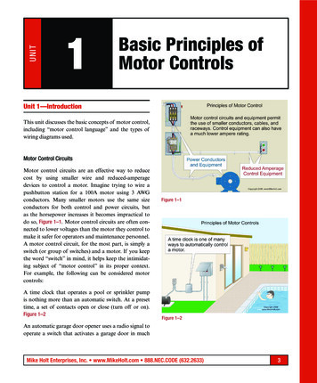
MDLAbout Motor Design LtdSoftware developers: Motor-CAD Developers of Motor-CAD – world-leading tool for thedesign and analysis of electric motors High level of customer support and engineering know-how Developed with expert electric machine designers.Consultancy Design, analysis & training Led by motor design experts with significant industry andacademic experience.Research Involved in collaborative government/EU-funded researchprojects Collaborate with Universities worldwide to develop electricmachine modelling techniques and create validation data.2
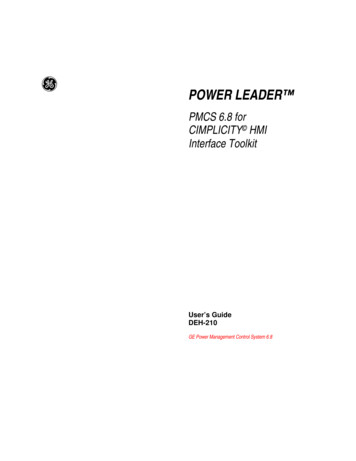
Motor-CADMotor Design Software The market leading tool dedicated to thedesign and analysis of electric motors. Enables rapid and accurateelectromagnetic, thermal and mechanicalanalysis of an electric machine acrossthe full operating envelope. Designed and developed in closecollaboration with expert electricmachine designers. Embedded engineering expertise. Great customer support and response touser feedback.3
Motor-CADMotor Design SoftwareSlot temperaturedistribution Covers all typical types of radial fluxrotating electric machines Motor Types:‒ Brushless permanent magnet(inner & outer rotor)‒ Induction‒ Synchronous reluctance‒ Switched reluctance‒ Synchronous wound field‒ Permanent magnet DC‒ Single phase induction Uses a combination of analytical andnumerical modelling techniques3D visualisation and CAD exportTransient thermalanalysisFlux Density shadingEfficiency map4
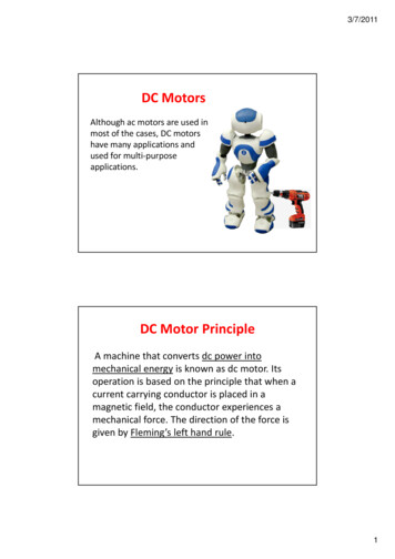
Motor-CAD EMagMotor-CAD electromagnetic module Extensive range of parametrisedtemplates & geometriesInterior PM machine designSwitched reluctance machinedesignSynchronous wound field machinedesignInduction machine design Calculates torque, power, losses,voltages, currents, inductances, fluxlinkages and forces. Designs can be input and calculatedin minutes allowing lots of iterationand full exploration of the designspace; ensuring optimal designdecisions.5
Motor-CAD EMagMotor-CAD electromagnetic module Combined 2D finite element andanalytical modelling approach Calculates electrical & electromagneticperformanceRadial winding patternInduction machine equivalent circuitFourier analysis of the voltagewaveformLinear winding layout Coupled solution with the thermal model Automatically set-up calculations fordifferent performance tests.6
Motor-CAD EMagMotor-CAD electromagnetic module Embedded 2D transient FEA solver Meshing, boundary conditionsautomatically set-up Advanced calculations such a eddycurrent in magnets, inductionmachine rotor bars & AC windinglosses.Flux density plot from FEA solverCalculated voltage waveformFEA geometry and region editorAC loss in a hairpin winding DXF and scriptable geometries,custom current waveforms, multi-sliceskew. Enables engineers to account forcomplex electromagnetic effects earlyin the design process7
Motor-CAD ThermMotor-CAD thermal module Industry standard tool for thermal analysis ofelectric machines with over 20 years ofinbuilt experience. Calculates temperature of the motorcomponents in steady-state and transientoperating conditions. Enables accurate modelling of thermalbehaviour within seconds of calculation. Enables understanding of main heat transferpaths and opportunities to significantlyimprove output. Allows iteration and full exploration of thedesign space, alongside electromagneticanalysis; ensuring optimal design decisions.Visualisation of oilspray coolingRadial temperaturedistributionThermal networkThermal transient solution8
TENV: Totally enclosed non-ventilatedThermCooling Types‒ Natural convection from housing TEFC: Totally enclosed fan cooled‒ Forced convection from housingFan cooledmachine withcowling Through Ventilation TE with Internal Circulating Air‒ Internal air circulating path‒ Water jacket as heat exchanger Open end-shield cooling Water JacketsWater jacketwith axialchannels‒ Axial or circumferential Submersible cooling Wet Rotor & Wet Stator cooling Spray Cooling‒ e.g. Oil spray cooing of end windings Direct conductor cooling‒ e.g. Slot ducts with oilThroughventilationwith radialducts9
Motor-CAD ThermThermal Network Thermal and flow network generatedautomatically 3D network includes radial & axial heattransferCross-Section Showing AxialTemperaturesSlot cross section for aconcentrated windingThermal Resistance NetworkSlot cross section forhairpin winding Detailed visualisation and calculation ofthe slot cross section CFD, FEA and empirical correlationsbehind all calculations.10
Motor-CAD ThermManufacturing Data Thermal modelling of electric machine can be challenging asthermal behaviour is significantly affected by manufacturingaspects. Examples of manufacturing uncertainties that affecttemperature rise:‒ Goodness of effective interface between stator andhousing‒ How well the winding is impregnated or potted Equivalent interface gapthat is useful for non heattransfer specialistExperience is built into the software to assist users inselecting appropriate values.Interface resistance andconductance data that issuitable for thermal expertsExample ofguidance given toset stator laminationto housing interfacethermal resistance11
Motor-CAD LabCalculatedefficiency map inmotoring andgenerating regionMotor-CAD Virtual Testing Laboratory Efficiency & loss maps Peak torque/speed curves Continuous torque/speed curves Duty cycle analysis Open & short circuit testsCalculated lossesover time for aduty cycle Automatically applies maximumtorque/amp control strategies toreplicate performance of machine withinverter Essential calculations for designing andanalysing inverter driven machines withrange of operating conditions.12
Motor-CAD LabModel buildinterface inMotor-CAD LabModelling Approach To generate the map and cycle data,thousands of operating points have tobe calculated. We use the FEA and analytical EMagsolvers to build inductance and lossmaps of the machine design. Couples with the thermal solver topredict combined EMag and thermalbehaviour.Response surfaceof iron losses vscurrent magnitudeand angle,calculated usingthe FEA solver All calculations efficiency maps, dutycycles etc. can be calculated inminutes, and hence used during aniterative design process.13
Motor-CAD LabPeak and continuous operation Machines are often specified on theirpeak and continuous operatingcharacteristics. The peak curve is typically constrainedby the inverter current limit and DC linkvoltage. The continuous operating curve istypically limited by the winding and/orthe rotor temperature. The lab model can be used to easilygenerate these characteristics curves forany electric machine design.Transient operationregionTorque is limitedhere on maximumwindingtemperatureTorque is limited here onmaximum rotor/magnettemperatureCalculated peak and continuous torque/speed curves14
Motor/Generator: Time vs Torque vs SpeedMotor-CAD LabCo-solvedelectromagneticand thermalbehaviour overcycleDuty cycle analysis Losses, efficiency and energy usagecan be calculated across any dutycycle. The behaviour of the machine issolved with the thermal model to givetemperature rise against time.Motor/Generator: Temperature Vs Time The variation of losses and magnetflux (torque/amp) with temperature isaccounted for. This enables engineers to design amachine with minimum size/cost andoptimise the design for maximumcycle efficiency.15
Motor-CAD MechanicalStress Analysis for High Speed rotorsVon Mises Stress in IPM rotor at maximum speed FE solution based Very fast – solves within acouple of seconds Template or DXF importoptions available Enables engineers to considerMagnetic and Mechanicalperformance trade-off in designoptimisation16
Motor-CADUsage in development lifecycle Motor-CAD is primarily used byelectric machine designers It is particularly useful for initialdesign, topology selection, sizing,analysis and optimisation acrossthe full operating envelope. However, it can also be usedalongside 3D FEA and CFD toolsfor more detailed analysis in thelatter stages of design. Motor-CAD software’s usabilitymeans that it can also be used bynon-experts in electric machinedesign.Verification &ValidationConcept ofOperationsInitial design,topology &sizingOperation &MaintenanceSystemVerification &ValidationRequirements &ArchitectureDetailed DesignDetailed design& optimisationIntegration,Test andVerificationImplementationTimeEngineering product development lifecycle17
Test rig input data,model validation &analysisMotor-CADUsage in development lifecycle Motor-CAD is useful for systemsanalysis; to generate reduced orderthermal models, flux linkage/inductancemaps, forces for combined motor andgearbox analysis, co-simulation withsystem tools etc. It is also really valuable to use duringthe motor test and validation process.This often helps provide input data forthe testing and helps identify anymanufacturing issues with the machineand provides improved modelling for thenext design iteration.Verification &ValidationConcept ofOperationsOperation &MaintenanceSystemVerification &ValidationRequirements &ArchitectureDetailed DesignIntegration,Test andVerificationImplementationReduced ordermodels, couplingand co-simulationTimeEngineering product development lifecycle18
Software LinksMotor Design Limited Software LinksMotor-CAD links to ANSYS software (Maxwell, Mechanical, Fluent)Motor-CAD couples with OptiSLang to provide cutting-edge optimisation workflowMotor-CAD links to RomaxDESIGNER software (Transmission Integration & NVH)Motor-CAD links into GT-Suite for co-simulation and model exportMotor-CAD links to Simulink for electromagnetic and thermal reduced order modelling19
This document contains proprietary information of Motor Design Ltd.Such proprietary information may not be used, reproduced, or disclosed to any other parties for any other purpose without the expressed written permission of Motor Design Ltd. Motor Design Ltd 2016 All Rights Reserved.20
MDLAbout Motor Design LtdResearch‒ Concept e – Prototype Electric vehicle developmentwith Jaguar Land Rover (JLR)‒ HVEMS – High Volume E-Machines ManufacturingSupply. Make-Like-Production prototyping facility in theUK with JLR‒ Tevva – Design of SRM motors for Trucks‒ ReFreeDrive – Rare Earth Traction motors withimproved performance and lower cost (Induction andReluctance Motors)‒ ELETAD – Helicopter electric tail rotor21
Motor Types: ‒Brushless permanent magnet (inner & outer rotor) ‒Induction ‒Synchronous reluctance ‒Switched reluctance ‒Synchronous wound field ‒Permanent magnet DC ‒Single phase induction Uses a combination of analytical and numerical modelling techniques Motor Design So