Transcription
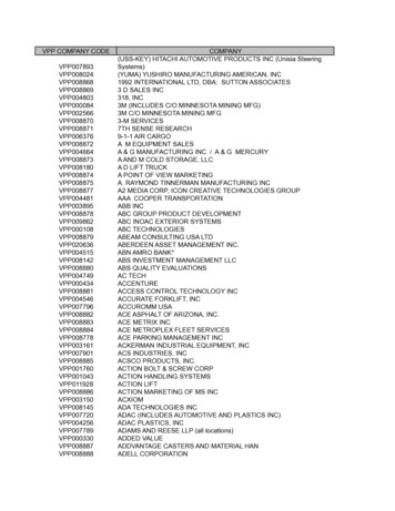
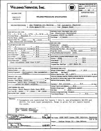
."WESERvicEs,INCWELDINGwps-.' WELDING PROCED)URE NO.WE-(GPRCEUEO111 432REVISION A0317 4-NNC'LDING. .1PAGEOF2SUPPORTING PQR(S)WELDING CODEA03N432WELDING PROCEDURE SPECIFICATIONASME B & PVSECTION IXWELDING PROCESS(ES)i.Gas Tungsten Arc WeldingTYPE2. Code cape N 432BASE METALS (OW-403)to P No. 23- Gr. No.P No.3"MaximumThichness RangenonePipe Dia. RangeRange for Fillet. Thk.noneDie.Max Deposited thickness 3"FILLER METALS (W-4O4)FNo. 1.62.Gr. No.TYPE.POSTWELD HEAT TREATMENT (OW-407)ResistanceElectricalType.IN. TemperatureIN. Time RangennneN/AN/AN/AN/ASize of Filler 1.035"Electrode - Flux Class nonenoneConsumable insertlessPass thicknessN/A2.GAS (OW--408)"Shielding Gas 1.PercentComp.Argon)9995%Shielding Gas Flow Rate40 to 50PurgeGas noneFlow RateTrailing Shielding Gas Composition-none.than 0,50"POSITION (OW-405)-125"9WTHCFH(min)CFH(min.)noneIN.-IN. -ELECTRICAL CHARACTERISTICS(OW-409).2.Current1. DCEN2.Amps Range 1. *2. .*Volts Range l.Tungsten Mec. Size/Typewelding PositionWelding ProgressionOF450OF to 550'F2 hoursIN.N/AANo.1. See Chemial AnarJsisSFA Spec. No. 1.I 282.AWS Class. No. 1.FR8nl,05,-D22.Size of Electrode 1.N/A2.Automatic (Machinbe),Temper BeadN/AN/A/A2%TECHNIQUE (QW-41 0)2(Horizontal ;sheets,See parameterStringer of Weave Bead 1.StringerBead WidthSee Page 2Orfice or Gas Cup Size #4 (.250")2:N/AIN. (min.)Initial and Interpass cleaning: Welding surfaces shall be wire brushed or groundOF (Min.) as requied to remove slag, scale or other contaminants.PREHEAT (OW-406)Preheat Temp. 300 OFInterpass - Temp. Range 45 0 F MaxOFPreheat 30 minutesMin:PreheatMaint. '30Fpriorto startwelding,JOINT DESIGN (E-402).Weld Repair Code Case N432GrooveDesignJoint Type OB -noneCnoneBSnoneBacking Mati TypenoneMethod of back gougingnoneOscillation 1. Not ,allowed2.N/AContact Tube to work distanceN/AMutipleorslngle Layer I.MultipleLayer2.N/A(PerSde)Multiple or single electrodes SingleTravel Speed (Range) 1. *IN. (max.)IN.2.N/AIPMREMARKS*Parameters are restricted for layers 1 thru 6,QW-410, for each layer parameters.see attachments QW-409 andRange is given for all layers beyondthe sixth. 8911220164 89111-7PDRADOCK 05000247PDR@ i/I2t/iFab.Codes: ASME B&PV Codes 1981 Edition, SectionsIII & IXProject:Indian PointIIMaterials EngineeringSobNo.Quality Assuince.- Con Edison
WELDING PROCEDURE NO.WELDING TECHNIQUE SHEETPNO. R Eu MTHK. RANGE "Maximum3TOPNO.GROUP.133WPS- A03174-N4321REVISION3'GROUP"I.IN.,TYPICAL JOINT DESIGNS PERMITTED Plate Dimensions 12"x30",PAGETOLAYERSINGLE VALUES ARE MINIMUM-FILLER METALSIZE-PROCESS(AWSGASfMAX.TELECTRICAL DAT A-CLASSTYPE(IN.)1GTAW2GT 0/',GTAV4 LT35LOW.RATE (CFH)SHIELD.935ER80S-D2,,0-L":A-'noneoE5R80S'2, ',L«-:.L5.4t) GTAWTYPE/lYPURGE POLAR.nonet9 20. . . ." Y-125NP194o"-B13B150B8 .9,B9.19.".2.7-5.0PREHEAT TEMP.0.i01 Loverlap"1- n 4)40-60% none-BACK GOUGINGMETHODTINTERPASS TEMP. 490 MaxOFCONTACT TUBE TO WORK DIST.N /APREHEAT MAINT.0.min,,prior-tc.welrdanjL OFIFI EORCUPSIZE -1: #4 (.250!!)EWTh.2%Wee;'NINSTRUCTIONS .i.:TIN. WELDING PROGRESSION.52k'-3.2P9.9885- to -25025.(IN.).375"B9.4 13.4"'3,B140.7 t:). 13.2WIDTH"'3.2B9.2P9'.8.P220TUNGSTEN ELECT. SIZE & TYPEIN.IN.B .,BS.e!WELDING PARAMETERSWELDING2ROOT OPENINGS O.B.7 1/4" thick.NObTOF2IN. (min.)IN.(min.)See technique sheetst-ech!gique sheets'' *'::c.it . : F, -,;Preheat to 300OF 30 minutes prior to start of weldinj10" ar 6nd ar4-to'bewelded.Thermocouples and recording instruments shall be used to monitor preheat, interpassand pQst.weid-hqat trat ment.o.pd.r.,.-,No oscillat'ion is5.6.7.8.9.10.11.to be used on layer,lt.hiugh,.cr5.Peening is not permitted.Parameters for layers 1 thro uh6s stated inQW409.pd.QW410 .hall,.be strictlyadhered2 .CI'. .I'.6 ,.d. (Weld heat iTn bu OCoiyi-si taisough"ahl l'e i10of 09QWsA and W41OITravel speed shall be measured at the work .irfce.''Welding power supply shall be Gold Track II or equivalent.When welding is done remotely, optics for weld puddle shall begin working order.After welding, no non-destructive examination shall be performed for 48 hours.The finished surface of. the repair shall be substantially flush with the surfaceof the component surrounding the repair.
1.7. -2C , . ,I4K,P . **Wel.WZ?-2Ti3,ZNC.WELDING SERVICES,INC.):',ELE:TNG PROCEDURE SPECIFICATION"S }'CIAL INSTRUC I.NS.We1Cdngof.-iA-the- re-ai-r- area- :hall- b bns, and ;delin :foll.wJ. ng insftu1.The area to be repairedby weiAdng,-f:nd an, ghearea, shall'eprelhet-d to "-30Q dec"rees,.i ,tempirature shall 45e I ainaiLaat-least- 3 , d-tAesbefore welding is started, dur ng w:lding, and' u til .starting the postweld heating *as: dqscribe3 below.2.The width of: the Preheat (band shall be at 1 ,a t threetimes thb thicknessfof the cynpbnrit to be w l.ded!apd :asneEded to--accommsdate -hermocb'jae--at achmcnt- and" --tr-ation application, -but need. .co,'.,:3.4.The into6.sh.ncbes.i45eThermo&cup -es and fecordrignstrmments sha-r be used to--monitor - pret-h,--intoerpa.T.t.;tE:per6ature.Thermocouples may be attb.ch :d by mechanical methods orapaLtor,5.t,1 peratur4as7ee-d t.t.(s charge-.,".The first six(6) layers of woldjbde0Vtit--- shall :- .as shown on the attah d, .ctcha,.'*. z,.The' Weld heat in ruit f'dr eachshal!.be controledto w thin.p r o ce diaur ec ati p., ,Letl ,.'-irst sixf.;,- h.-*JJ-'.ofZ, .-*.C,- rappj.i-,;Lirj().einpiU.L,.laye z .-.b-itae, : .-w''I,q'T .
Welding Procedure No.WPS-A03174-N432Page 2 of 27.The remainder of the weld deposit shall be completed withthe heat input equal to or less than that used for layersbeyond the sixth in procedure qualification.8.At the:D!,pletion of wCe71.ng, the heated bend described in#1 and #2 above, shall :je maintained in the r-ange ofdecrees F /'- 50 degrees for two (2) hou -s miinua.500
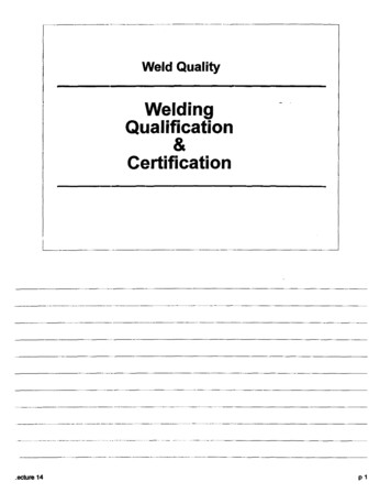
WELDING SERVICES, INC.WELDING PROCEDURE SPECIFICATIONWelding Procedure No. WPS-A03174-N432STEP 1: Deposit layer one withfirst layer weld parametersused in qualifications.STEP 2:Deposit layer two withsecond layer weld parametersused in qualifications.STEP 3: Deposit next four layerswith layer three through sixweld parameters used inqualifications.STEP 4:Subsequent layers tobe deposited as qualified.AUTOMATIC OR MACHINE (GTAW) TEMPERBEAD TECHNIQUE
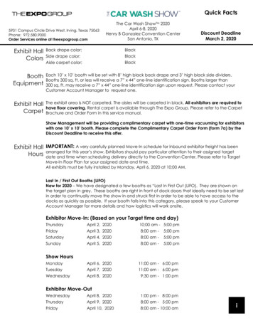
(.Temper Bead GTAWRef. Code Case N-432lOAttachmenLElectrical Charecteristics (QW-409)LayerCurrent: DCENPulsing CurrentLow Pulse Frequency 20Low Pulse Width 6 6Machine ModeAmperage:.PrimaryPrimaryWire Feed: Primary. 35.180BackgroundVoltagePulse ArcBackground1209.7Background 8.9TungstenSize .125aTypeEWTh 2%Technique (QW-410)Layer1Stringer Beads OnlyGas Cup Size #4(.250") Min.Multiple LayerSingle ElectrodeTravel SpeedjMHEAT INPUT SHALL NOT EXCEED 10% OF THE ABOVE PARAMETERS
Temper Bead GTAWRef. Code Case N-432Attachment 2Electrical Charecteristics (QW-409)Layer 2Current: DCENPulsing CurrentLow Pulse FrequencyLow Pulse Width66Machine Mode Pulse ArcAmperage:Wire Feed: y 9.6Background 9.1TungstenSize .125"TypeEWTh 2%Technique (QW-410)Layer2Stringer Beads OnlyGas Cup Size#4 (.250")Min.Multiple LayerSingle ElectrodeTravel Speed 3 ZTpMHEAT INPUT SHALL NOT EXCEED 10% OF THE ABOVE PARAMETERSy
Temper Bead GTAWRef. Code Case N-432Attachment IElectrical Charecteristics (QW-409)Layer 3Current: DCEN-Pulsing CurrentLow Pulse FrequencyLow Pulse WidthAmperage:066ArcMachine Mode,Primary 2 m.-Wire 9.8Background9.2Size .125"TypeEWTh 2Technique (QW-410)LayerPrimary . 5 03Stringer Beads OnlyGas Cup Size#4 (.250") Min.Multiple LayerSingle ElectrodeTravel Speed Z.2 PMHEAT INPUT SHALL NOT EXCEED 10% OF THE ABOVE PARAMETERS
Temper Bead GTAWRef. Code Case N-432AttachmentElectrical Charecteristics (QW-409)Layer--- thru 6Current: DCENPulsing CurrentLow Pulse Frequency 2Low Pulse Width. 66Machine Mode Pulse ArcAmperage:PrimaryWire Feed: Primar.YL.Backgrou.djVoltage.Primary 220Background 140Tu\ngstenSize .125"Tv.e:,71-i 2/%Technique (QW-410)Layer 4 thru 6Stringer Beads OnlyGas Cup Size#4 (.250") Min.Multiple LayerSingle ElectrodeTravel Speed -. 4IJPMHEAT INPUT SHALL NOT EXCEED 10% OF THE ABOVE PARAMETERSBackground.504
dTemper Bead GTAWRef. Code Case N-432-Attachment 5Electrical Charecteristics (QW-409)Layer 7 thru Remaindercurrent: DCENPulsing CurrentLow Pulse Frequency 2.3 to 2.Low Pulse Width U to 60Machine Mode Pulse ArcAmperage:Primary 2 to 260 .Wire Feed: Primary 10-90Backgroupd IM to 170VoltagePrimary 90-1Background 1 0-Q.5.Backgrou4 8.j 5.5. 0TungstenSize .125"TypeEwTh 2%Technique (QW-410)LayerStringer Beads OnlyGas CupSize#4 (.250") Mn.Multiple LayerSingle ElectrodeTravel .Speed7HEAT INPUT SHALL NOT EXCEED 10% OF THE ABOVE PARAMETERS?---"-.[2 : --,.
QW-483SUGGESTED FORMAT FOR PROCEDURE QUA-LIFICATION RECORD (POR)(See QW-201.2, Section IX, ASME Boiler and Pressure Vessel Code)Record Actual Conditions Used to Weld Test Coupon.Company NameWelding Services Inc.Procedure Qualification Record No. A03N432 Revision 1-WPS No.Date6-22-89A03174-N432Welding Process(es)Gas TungestenTypes (Manual, Automatic, Semi.Auto.)ArcWeldingAutomatic(Machine)!! 60JOINTS (QW-402)tAN&C4.INOTTOGroove Design of Test Coupon(For combination qualifications, the deposited weld metal thickness shall be recorded for each filler metal or process weld.)BASE METALS (OW-403)POSTWELD HEAT TREATMENT (QW-407)Material Spec. SA 102Temperature500 FType or GradeTimeB3P-No.Thickness of Test CouponDiameter of Test Coupon2HoursOther Cool to ambient temperature for 48toP.No.7.25 "hours prior to any testingnoneOtherGAS (QW-408)Type of Ggs or GesesArgon99 .995%Composition of Gas MixtureOtherFILLER METALS (0W-404)Weld Metal Analysis A-No. See ChemicalSize of Filler Metal.03l"DiaFiller Metal F-No.6SFA Specification5.28AWS ClassificationER80S-D2Anya1sisELECTRICAL CHARACTERISTICS (OW-409)CurrentDirectStraightVoltsTungsten Electrode SizeMax Deposited thickness 3"POSITION (QW-405)Position of Groove2GWeld Progression (Uphill, Downhill)HorizontalWeld bead placement is restricted for- .layers1--thru6- See attachmentsPREHEAT(QW-406)Preheat Temp. 3000 F 30 minutes prior to welding.InterpassTemp. 4500F maxOther Temperatures to be monitored by r* See Attachments for QW409Parameters are restricted for layers 1through 6,TECHNIQUE (QW-410)Travel Speed*String or Weave BeadStringerOscillationNot allowedMultipass or Single Pass (per side)MultipassSingle or Multiple Electrodes Single ElectrodeOther* See attachments for OW-410Parameters are restricted for layers1 thru 6recorder.This form (E00007) may be obtained from the Order Dept., ASME, 345 E. 47th St. New York, N.Y. 10017NOTE: This PQR was revised for editorial reasons.
OW-483 (Back)A03 N432., Tensile Test (OW-150)SpecimenNo.,Width2M, 2 4 7 7. 0 5.--Q0.2883MUltimateTotal LoadArea-UltimateUnit StressType ofFailure &psiLocation9.S400097500BMDlb.0.04820 04910 0486--0.24966B.' . .: ;Jhickness4530.4780477Q4800.0489Rev 1POR No.BMD98000798000Guided Bend Tests (OW-160)Type and Figure No.S1; -.21Result.224),," 1: PF .'-.q:BMDBMD.pal.-. .-:-- 3.Toughness Tests (QW-170)Specimen0o.No.NotchuJr,Location .s--Notch'.yeiTe tTem.f .SEE ATTACHMENTCL'mpactValues.,LateriIE3p% ShearMilsA--rp.WeightNo BreakBreak-,.Fillet Weld Test (QW-180)Result-Satisfactorv-Yps.-,.NoPenetration into Parent MetalYesMacro-ResultsNo.-Other TestsType of TestMT,Deposit AnalysisOtherUT,4bleloeptc iI K. .u.0sa*--"9110vI. '.1.51.e.i. . .:.::: .E' . . . . . a .V 5. . .K. Buba h/e.YV' t rt11we1Welder's Name.Tests conducted by:kLi.jJE7575HarmonC.APPLIED TECHNICAL SERVICES0.e1 /ScH6517Laboratory Test No. AO-O394&HO 0516We certify that the statements in this record are correct and that the test welds were preprared, welded and tested in accordance withthe requirements of Section IX of the ASME Code.ManufacturerDate'ByWELDING SERVICES INC.''.(Detail of record of tests are illustrative only and may be modified to conform to the type an4 number of tests required by the Code.)(6/82)L .-j,:'"'
ATTACHMENT ATPQR1V(5T. A03N'43'2TestsToughnessI. . . . .1.22tVnfl.x . .5'y A.:.r . .I3Aj :A.,T t,c4b,.-It -1TBase MealWeld M tal-"Specimen-Type p3,:Specim4nsASTM E208Specimens. .- .r-Drop Weight 9rests.-. .j ,.-'-10 degrees-F:-40 degrees F: Break.No-Break .-10 deqve 4ti-grF1N brr-eF:No break 20 Degreps. F:uf]iT 30 degrees F .Nil. e. 0-degre:s F:.No PreakDuctiLty -.20:Tempe ature/ --,- 40 degrees F: No--Break.-.Nil--Ductility- - .Te erature- --30 -d geree.F .CV TestsWeld Metal3-. .: .,2- : '163 :ft.lb. . 63---m i l s- l at .- ex p . .tc.---4Oegre s. . . . . .-. . .40% shear2:--105 ft-lb62 .mils- latex.705% shearRT NDT Tcv -60'h7-.Ai.q'.-RT NDT: -203: 80 ft-lbexp.62 mils lat.&M,,,q .shear4-",-gr-eS,l-7 7'v 173 aY U."I C1')'nberiborn Sr. ' F'MOf,virv3li ?' LNy ?1oEMS10O O)'1 J
ATTACHMENT APQR No. A03N432Toughness Tests(QW-170)Heat AffectedZone1: 46 ft-lb39 mils lat. exp.20% shearTcv 90 degrees FT NDT 30 degreesF (base metal-droptest)2: 51 ft-lb46 mils lat. exp.20% shear29 mils lateralexpansion and 28 ftlb. average for basemetalatTvc 90degrees F3. 35 ft-lb32 mils lat. exp.20% shearBase Metal3C1:27 ft-lb28 mils lat. exp.10% shearTcv: 90 degrees FC2:31 ft-lb28 mils lat. exp.10% shearT NDT: 30 degrees FC3:39 ft-lb37 mils lat. exp.10% shear
ATTACHMENT APQR No. A03N432Toughness Tests(QW-170)Base Metal3D1:39 ft-lb36 mils lat. exp.20% shearTcv:120 degrees FD2:27 ft-lb27 mils lat. exp.30% shearD3:34 ft-lb34 mils lat. exp.30% shearHeat AffectedZone1: 61 ft-lb45 mils lat. exp.50% shear2: 52 ft-lb47 mils lat exp.50% shear3: 49 ft-lb45 mils lat. exp.50% shearTcv 120 degrees F
Temper Bead GTAWRef. Code Case N-432AttachmenLElectrical Charecteristics (QW-409)LayerCurrent: DCENPulsing CurrentLow Pulse Frequency 2 0Low Pulse Width 66Machine se Arc1209.7Background 8.9TungstenSize .125"TypeEWTh 2%Technique (QW-410)Layer1Stringer Beads OnlyGas Cup Size#4 (.250") Min.Multiple LayerSingle ElectrodeTravel SpeedpMHEAT INPUT SHALL NOT EXCEED 10% OF THE ABOVE PARAMETERSI-
Temper Bead GTAWRef. Code Case N-432Attachment 2Electrical Charecteristics (QW-409)Layer 2Current: DCENPulsing CurrentLow Pulse Frequency2Low Pulse Width 6Machine Mode Pulse groundTungsten9.1Size .125"TypeEWTh 2%Technique (QW-410)Layer2Stringer Beads OnlyGas Cup Size#4 (.250")Min.Multiple LayerSingle ElectrodeTravel Speed. 2 T.IPMHEAT INPUT SHALL NOT EXCEED 10% OF THE ABOVE PARAMETERS
Temper Bead GTAWRef. Code Case N-432Attachment -Electrical Charecteristics (QW-409)Layer 3current: DCENPulsing CurrentLow Pulse Frequency 2Low Pulse WidthMachine ModeAmperage:PrimaryPrimary2,.se Arc,9.8Background 9Tungsten662nBackgroundVoltage02Size .125"TypeEWTh 2%Technique (QW-410)Layer3Stringer Beads OnlyGas Cup Size#4 (.250")Min.Multiple LayerSingle ElectrodeTravel Speed3,?JPMHEAT INPUT SHALL NOT EXCEED 10% OF THE ABOVE PARAMETERS//
Temper Bead GTAWRef. Code Case N-432AttachmentElectrical Charecteristics (QW-409)Layer-A- thru 6Current: DCENPulsing CurrentLow Pulse Frequency-2Low Pulse Width66Machine Mode Pulse ArcAmperage:Primary 22sBackground4jVoltagePrimary220Background 140TungstenSize .125"TypeEWTh 2%Technique (QW-410)Layer 4 thru 6Stringer Beads OnlyGas Cup Size#4 (.250") Min.Multiple LayerSingle ElectrodeTravel Speed-LAIPMHEAT INPUT SHALL NOT EXCEED 10% OF THE ABOVEPARAMETERS4
litAttachment 5Electrical Charecteristics (QW-409)Layer 7 thru RemainderCurrent:LkxNPulsing CurrentLow Pulse Frequency 2.3 to 2.6Low Pulse Width 50 to 60Machine Mode Pulse ArcAmperage:VoltagePrimary 20to 260Backgrund-1to 170PrimaryBackgroundTungstenSize .125"TypeEWTh 2%Technique (QW-410)LayerStringer Beads OnlyGas Cup Size#4 (.250") Min.Multiple LayerSingle ElectrodeTravel SpeedHEAT INPUT SHALL NCT EXCEED 10% OF THE ABOVE PARAMETERS/Temper Bead GTAW'Ref. Code Case N-432
-.rN .dTAlIANTA.SEOROIACOCDVr1.IK,.-3 DLdO?76 H-t a--Dr"veJ. O T .lol l oala.00 .0omltoku 0 ug ik u * c g g0oA Ug m *sw aWWSW iblkgaah,LWJLRJ2JLJ§JjMf6)rInlDIA. & VAILTXIC OhT.S*- aiIPI5ISDi-.off----yaI INIIli sJ'FRMAT 3oo F039?Uapamsosa ss%.0 "00DOOn-a'4lWOO.IJsNOfteatiob- ua.77LUtR MTERDIALITrnJFR 9 OS DSIZE.0359(TRAYLRrcTIrz o,Mor2.s Ro.I-V"LlIi. ii/ AJ Im'C.atvCCV ZML4JPrnE OFT n XInP RO -r 70AlS--Od970Cc AVTLO7'VP,MO ld 1rO rS.,jCUP. it. IOTUNG STLK Iroomr'pe i5*1 .O
(4)4z,,ooo5WILE7)ONCATLANTA."LI.i.N CODE:.ITlllW ieo cIA OX0I l' TKtIIIgap lmO li l utwml0b,rG ,6 1t''',1i1 IIiIKATERIAL1276 Harlan Drive*IOTANI@?OIM Ifoavel p illvj Jjja-lIi"-""gViSmug* ts P911 Fug Igleekpvl voegITK P, tMDIA. & VA!,TXIMM DSS0 ONI34lfl II ouEINSWIQ .%opt-fe.IN*TANgIMiyfwamv S ualaEI-lSN POSITION.S*Cmigpgw s %eea tI cZlist*, ",/0will EE L NIIMC 'I INlmmcmFEoof2vuoaLEE7b,. um.7ILAR MTERIAL,4TYM 8IZEE.C8o050zSnga"llI.IIourINVcl lilam-peivsSECOND LtPIE,.(sj --Fro,"COVA/EZL-J,qp "0ILrdrCUP, I(D.! 0,,TUNGSC)(I'LB,-4.Vy CVL JDL-UP.R.QE#mo-EapammIp"(TA 'RETZIhOF**I.M " orTrn OF onItl l0,1FAla03scI:- IE8'ccE? w i*1, '*-.0'.
ATLANTA.'ZIDZN, CODEo m0340.0kIiIPNa ilvlmI.ma 3276AHa0altmml ggmailm,Ni'IDr:0s0ntIfmI "fibK&TERMA9smugS5q-7oz2 6.)as3lsaiDIA. & MATy-?ooGaWtitl*aucI hrERPAss Z//os mtagaSollarvasej7LZRI URIALSIZETrPCCVCv3,.-V,O'/erLA'PT*n OF non .0'FwCUP.PO/(O3IE 8Errfu eC"er,"Nit.tiOE JWZ.offP u".p.-IN Nilllm 1mgI IllI'Pl 1 IIIM.b" manvFOSITIOTUNSDlusAMml I e-feavysLyIN
IrLEPNON) 43-2005AY#0LAN14%'.S.141'lo"00S4aaygwmfo. ATIRMMarian-276camv"Avttia u--sIi9.9ARINTln,I*riveISPv'Ii 0,aFlula"IPwIU*INDIA. & WALLTHI CKMESSOMSCIlull.w."rEnAToS ireIsaIv*iU'lt5ll 8U "etcSulD"taeSol,&AugP*XLLER KAMrIALDtI S IiliMi?ro-2,TlflV 1F.-cC-V-foUt TNo.fgILbutsoftof\baa.,'/14O014m ost"IC/'lrIlersoJer"-,T4.,I.HT.o *VERLAP * ronrP4C)31,ej /O)CUP. Mo. IoTUNCST mg ECOI'BI1*JAMES I p A-RAY(ifl9., 'uIm4gI IDLVUftI9%0,,
ALANT& Sto atA 30340. 176Haran IWING CODE(si-mpmsug5gsmalmy aatec '.5vm twealv0vi ima1W1ig 1 11PAIAI'VaawI11ll fDIh. & YAUtThi C)QTSSSl {rDIL1111I l INI IgmIw0i wi-ll I.11iy Bga I-DvTIM bell"WANTun goFix FPaOasmmlllmimcl.ia."Isli-O so obtatALA " 1. .a.t.1.fulWoaI "61477LLER K&ATRIALTYPESIZETRAMHor2./ A-. / U,F.SEVErg- LA.er 7-.Wlkub-s'ELOEAD PICEAhE T qS.EEEC p-o o.o* TMPfROF nonC In7TE ."70 CO'HAiCTC wEiD,9*OD. ,-'C.Pc,-rI t-0S-cuNp ItO oCLTP. /0TU NSTL- g(c DM*NT 8,ZU?mtL5N"cev.0Ilol P
CASEN-432CASES OF ASNIE BOILER AND PRELSSURVESSEL CODEApproval Data: February 20. 1916- '"See Numeric Index for expirationed conoeafflrmptiondreC&Case N-432Repair Welding Using Automatic or Machine GasTungsten.Arc Welding (GTAW) Temperbead TechniqueSection XI. Division 1IX and additional requirements of Section Ill, as niudi.fled by 2.1,2.2, and 3.0(c) and (J).2.1 Procedure QualificationsInqfliry: Ma) tile' ailtiamatic or machimI;i'TAW pro.ces* ie u1sed as an alternative to the SMAWR' process forperfomitig the teniperh,.ad technique on Ua.s I cornpollenth?Reply: It is the opinion of the Committee that repairto P-Nos. 1, 3. 12A, 1211, and 12C base material andassociated welds may be made by the automatic ormachine TAW lemperbead techniqe without thespeci.fled postweld heat treatment requirements of SectionIII, provided the requiremenLs of 1.0 through 5.0 beloware met. The depth otfrepair is not limited provided theteet as smicll mrets the rrequin'me.nt lf2.1.1.0 GENERAL REQUIREMENTS(a) Tle requirei. gith or IWA4(Xi(1, as apliceable,shall Iet'int.(b) Only the automatic or ma,-hine (;TAW proecssusing cold wire fee d shil be used. No arc oscillationiall be used.(c) W.'Idig material! shall be coontrolle'd during repair so that thae'yarc identified as acceptable materialuntil vomsunmed.(d)TIl.eae'mtrinm fluuem in te"repair art-as shall beal,-si initoarccmnt %fhrsr'.tablibhi.g the weld metalcompisetieara linmie.(P) Pe'miimg *11al nitl I permie d.(a) Tlme test assembly materials feir the wcllineg iro.cedure qualification shall be of the salie speiricatitintype, grade, and class as the materials being repaired.The test assembly shall receive a poitield heat treatlseistthat is at least cquivalent to the time and temperatureapplied to the materials being repaired. The procedureand perfunnance qualification tests may be osmtbip,.d,provided Section IX requirements are met. The test assembly dimensions, including joint details, shall be documneeted on the PQIi. (b)Th. test assembly thickness shall be at lertrtetimes tile depth of repair, but nveed iit exceed tile thicksloes. t [ime material to lie repaired preividd thi re-quiiredtest slt.cimei can be removed. Wien'i lite thit Lee-,iSiftlst la-e iirtal to be repaired is greater tlia. 2i i. Ih,deplth iltie cavity in tie test asbrinlly seall le tiegreater tof I in. or the depth of the cavity Itsloe'rel-liail.lowev.r, in no case shall the pr(ceellre ilualilicatitan testasenbly be less than 2 in. thick, nor shall tileh lih ofthe cavity in the test assembly be less than I ins.(c) The te t assenitly diniensiuns semrrmiidiiig thai:cavity shall be al least lice tIickness of the cwaili.oit atthe' location of the repair or 6 in., whichever i.gr,-ate-r.If the re-'airweld is to be prrfir.d rm:etmt'i,.i1,' lai.ce'dure, qualification, lest assembly shall be- ,'u.,iel,,te.dwith tile salmi t duplicate irenming andel eiee lrIleqiiij.nmellotlia t, use'il fir the' repair. Ti le' t'sa.'saill hallAniielatl' t-e pitilii and bstructictnrm eelisti- ait-ilIe'imair.2.0 WELDING QUALIFICATIONSTh," W'i iing Pr.'.dore Sl,,.rifivation aoid the we'ldisigool,'rateors shal b. q ialifieel in ar:,irdair', with Se'elien'P.No. 12A. 1210. and 124:dr'iaeli,re. rr'.r t s,,l'ifr mihetrialecfireaiois,erindnallh i.ififi,.d in,Se-iin Ill. ald .wilowtqe.'ie.i)rrrlaeii'ed in a li'r ediliN, 401 Set'11m Al.(d) h'lereott width arid time'immi'hldI'atiililmliaii.,' il tIhrill' 'llartab. eibl) ,hall hi,sie gre'at-'rii sp'cifieid Illlin'u.o-edil il, re.'ir.hli tamd.(e) "l'ii6 te',t Ue.s'ill nai)i)li . .4 ltee 4 h iai r0 ,eitn'e. etr #eIehl buildup sof prrir., rllaiiiiii ai ateril,.pooir tim.milliatiellm. tihe' do'1 1 tipe i,-eas'vit) hiall littltoe.h', Ililiih,tlistirkiil.lt 111e'vll lellilill.ir I ilm.wioil'ievr i;Ngr'allr. Itsailijiem. tImt are's uelIlle10i1A-I.2noppiWN--N-wwmmm-.ii
CASE (continued)N-432CASES OF ASME BOILER AND PRESSUREVESSEL CODEshall not be less than the area of tilewell buildup to b.applied or 54 sq in., whichever is less.e() For all applications, the lestassembly and cavit)shall be of sufficient sizeto obtain the required lesispecime:ns.(b,) Welding material shallmee.t the reqlireneni iSeetions IX andN2.-h-,ll lIeperfer,,med illaccordan.,. it i Sec tioriIX ellIll fior groove %rlds, andthe Edition and Addendashallbe, stat.d in tile repairprogram. Dropweighttests,impact tests.Welding of the cavity or areabeing repaired shall bein accordance with the following.(a) The cavity or area tohe repaired by welding anda band around the cavity orarea300*F minimum. This temperatureshall be preheated toshall be maintainedfor at least 30 min beforewelding is started, duringweldinf, said until startingthe postweld heat treatmentof 450 F to 550*F describedin (e) below. The width ofthe Land shall be at least threetimes the thickness (37)of the component to he welded,but need not exceed 10in. The component thickness(7) shall be determined forthe area to be welded priorto formation of the cavity.The interpass temperature shallnot exceed 450 F.(b) Thermocouples and recordinginstruments shallbe used to monitor the preheat,interpass, and postweldheat 'treatment temperatures.Thermocouples shall he at.tached by welding or mechanicalm.thods.(c) The first six layers of thecavit" shall be butteredas shown in Fig. 1, Steps I through3.(d) The essential welding variablesshall be controlledas follows.side bendIitransition temperature (RtTDT)of the weld--"wzmetalInl-seNB 00 metalf, shall be establishedinaccordancewith0 f RTN is less thanor equal to 60 0 F,tilequa ification test shall beRT.VDT is greater than 600F, conisidered acceptable, Ifthe qualificatiun test shallle rijt'cte.d and a requalificaimnof the procedure shallbe performed. Test specimensshall lie obtained from thecompleted test assenblyat the maximum practicaldepthof rtpair.(i) Impact tsting of theprocehre qualification testas.,'nbl% HAZ shall be conductedas follows.The TNDT of the unaffectedbased material shall bedetrmined by dropweighttest to establish the testtemlerature for the C,tests.The Ce specimens represent.ing tileIIAZ material and th.sall b, tested at the (T.'DT unaffected base material 60 F) temperature oftheunaff,.ct,.d base material.The HAZ.C, absorbed energyaill lateral expansion shallbe equal to or greater thanIll,uiafft'ct,.d ba.e material atthe (N 7')T 60UF) t'nlieratlrc of the haze' material.2.2 Performance QualificationTil, weldiing operator shall bequalified ill accerlao.ewill Sction IX andi Ih.f-Jl, ing addition.ul reqoire.t'o.-. If til r,.pair %,.Ildis to lirperfoni d W.her.I111.i,'al.lltnie.jtimiimpair ihe' w,'ldingoperalor'b abilit)thp,'rfnii , ti,"w,'ling ,'liratr shall al.o d,:nin.,trath.thI,. abilil tI',, e,.' .iuil'I o4-'l,l ei'tal ill ti.oJe.,itioll.rt"l'lir'e , i.if,ihl i. sat,', partel,.t,.rs ami oiiiillhdIh. ial -h.-Inietitins tIhatare inoh'd ill tia- r'pair. or duplicate sensing and controlequipmelt tobe used for tie repair. Forthese applicatiolis, only non.destructive examination3.0 REPAIR WELDINGtests, and all weld metal tensiontests of the welI depositare required. A referencenilductility-Also, if tile repair weld is to be performedremotely, thepec.vmance qualification test shallbe coilipleted withlthesameof the weld is required.Tileprocedure and welding opcrateir performance qalifia.ion tests may be combined, provided ection IX require.mentsare met.Ill, and the Editiun and Addenda ofshallbe mtated in tie repair program.Th,. appropriate tough.hess tetiiig requirementsof NI-2000 rhall be completedfor tili: uld materials used.(h) Wdling procedure qualificationdestructive testsh .(I) Tile weld heat input for each oftilefirst sixlayers shall be controlled to within IO'/A of that used inthe procedure qualification test.(2) The remainder of the Welddeposit shall becomleleted (see Fig. I, Step 4) withthe heat input equalto or less than that used for layersbeyond the sixth intheprc-'edore qualificationi.(3) Th. finished surface of th,.repair shall be substantially fl.-h with the surfaceof the. component sur.roindui./ig tIII"re'pair.(4) 'l,. ti'einhilur descril,welin this plaragralplsshall he-perfin.,.dl in the procedur,,qualificatin, t'st.(P) At tll'. compl,.ion ofweling. tlia! 37' land1 a.,d,'fiul'd il (a) aie eve i allbe maitaned in the rang: ,if.4l50 1- toa5500F1for at lea.tI 2 hr.A-1.3
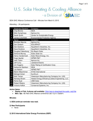
CASE (continued)CASES OF ASME BOILER AND PRESSURE VESSEL CODElayer one withStep 1,:Depositlirsl'ayer weldparameters used inquail fications.Step 2: Depositlayer two withsecond layer weldParameters used inqualifications.Step 3: Depositnext four layerswith layer threethrough sixweldparameters used inqualificationsStep 4: Subsequentlayersto bedeposited asqualified.FIG. 1AUTOMATIC OR MACHINE (GTAW) TEMPERSEADTECHNIQUEA-1.4N-432
CASE (continued)N-432CASES OF ASME BOILER AND PRESSURE VESSEL CODE4.0 EXAMINATION(a) The repair area and the 3T band as defined in3(a) shall be nondestructively examined after the completed weld has been at ambient temperature for at least48 hr. The nondestructive examination of the repairwelded region shall include radiography (if practical),ultrasonic examination, and surface examination.(b) Areas from which weld-attached thermocoupleshave been removed shall be ground and examined usinga surface examinatioi, method.5.0 DOCUMENTATION'iThe use of this Code Case shall be recorded on FornNIS.2 or other applicable docunients.71.11'1A-1.5
* 'STRUCTURALINTEGRITYASSOCIATES, INC.3150 Almaden ExpresswaySuite 226San Jose, CA 95118(408) 978-8200M3ssil8SMay 31, 19896.AJG-89-035.TELEX: IM17 STRUCTFA: (408) 978 894P,1 OperationsuM er R dSute I0A(o )o 4313(216 8 8 6FAX: (216) 869-5461Mr. S. BurkhalterWelding Services Incorporated3276 Marjan DriveAtlanta, GA 30340Subject:Revision to Letter AJG-89-031, dated May 19, 1989,"Consulting SupportforQualificationof WeldingTechnique for Temperbead Welding on Indian Point Unit 2Steam Generator Shell"Dear Steve:The purpose of this letter report is to document my review of theresults of the subject temperbead welding qualification testprogram conducted by Welding Services Incorporated (WSI) forConsolidated Edison Company.The temperbead qualification wasperformed for the Indian point Unit 2 (IP-2) steam generatorshell.The shell material is SA302 Grade B low alloy steel,designated by the ASME Code as P-3 Group 3 material.' The purposeof the temperbead qualification was to be prepared to perform acavity weld repair to one or more of the IP-2 steam generatorshells using this welding approach, such that an elevatedtemperature (11500F) post weld heat treatment would not berequired.ASME Code Case N-432, issued in February, 1986 [1],provided guidance for the temperbead qualification activity atWSI.Both weld parameter trial tests (on a thinner plate ofSA302 B material) and procedure qualification tests (on a thickerplate) were performed in order to select a weld procedure andthen to qualify it. Although a dilemma arose wherein the thickerplate was not entirely representative in terms of toughness, theresults on the thinner and thicker plates, taken together,demonstrate that the procedure should be technically acceptablefor use on the 3.5 inch thick steam generator shell at IP-2, asdiscussed in the following sections of this report.Weld TrialsIn the technical progr
Welding Procedure No. WPS-A03174-N432 Page 2 of 2 7. The remainder of the weld deposit shall be completed with the heat input equal to or less than that used for layers beyond the sixth in procedure qualification. 8. At the :D!,pletion of wCe71.ng, the heated bend described in #