Transcription
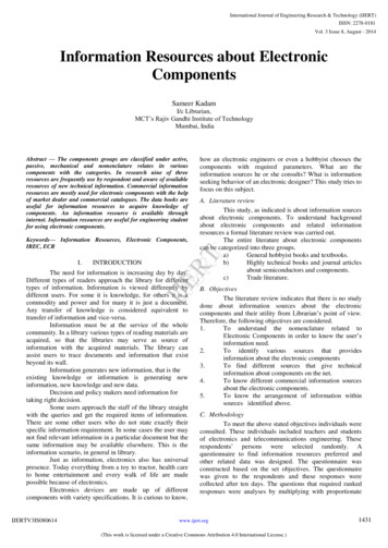
Familiarisation of Electronic Components and Equipments1Electronic ComponentsGenerally electronic components are classified into Passive componentsPassive components are the components, they themselves are not capable of processing anelectrical signal such as amplification, oscillation, modulation etc. But these components aid theactive components in functioning. The behavior of passive components is linear.Examples: resistor, capacitor, inductor and transformer. Active componentsActive components are those, they actually processing, when signal passes through it. Thisprocess may be amplification, modulation, frequency conversion etc. The behavior of activecomponents is nonlinear.Examples: transistors and diodes.An electric circuit becomes an electronic circuit when it has one or more active component(s).However, an active component all alone cannot perform any useful function.ResistorsA resistor is a device which provides a force opposing the charge-flow (or current) in acircuit. This opposing force is called resistance (R). It is measured in ohms (symbol is Ω. All resistorshave power ratings. It is the maximum power that can be dissipated without raising the temperaturetoo high. In electronic circuits, the common standard power ratings are ¼ W, ½ W, 1 W and 2 W.Fig: Resistor Symbols
Familiarisation of Electronic Components and Equipments2There are two basic types of resistors.1. Linear Resistors2. Non Linear Resistors1. Linear ResistorsThose resistors, which values change with the applied voltage and temperature, are called linearresistors. In other words, a resistor, which current value is directly proportional to the appliedvoltage is known as linear resistors.Generally, there are two types of resistors which have linear properties.a) Fixed Resistors b) Variable Resistors.a) Fixed ResistorsAs the name tells everything, fixed resistor is a resistor which has a specific value and we can’tchange the value of fixed resistors.Types of Fixed resistors.1. Carbon Composition Resistors2. Wire Wound Resistors3. Thin Film Resistors4. Thick Film ResistorsCarbon Composition ResistorThese types of resistor are very commonly used low cost resistor. The construction of carboncomposition resistor is very simple. It is also commonly referred as carbon resistor. It is mainly madeof carbon clay composition covered with a plastic case. The lead of the resistor is made of tinnedcopper. The main advantages of these resistors are that they are easily available in local market invery low cost and they are very durable too. But the main disadvantage is that they are very muchtemperature sensitive. These resistors are available in wide range of values. It is available in as lowas 1 Ω value and it is also available in as high as 22 Mega Ω value. The tolerance range in resistanceof carbon composition resistor is of 5 to 20 %. Such resistor has a tendency of electric noise dueto passage of electrical current from one carbon particle to other. Where low cost is the maincriteria of designing a circuit rather than it's performance, these resistors are normally used.
Familiarisation of Electronic Components and Equipments3Wire Wound ResistorThe first commercial resistors made were formed by wrapping a resistive wire around a nonconducting rod. The rod was usually made of some form of ceramic that had the desired heatproperties since the wires could become quite hot during use. End caps with leads attached werethen placed over the ends of the rod making contact to the resistive wire, usually a nickel chromiumalloy. The value of wirewound resistors remains fairly flat with increasing temperature, but changegreatly with frequency. It is also difficult to precisely control the value of the resistor duringconstruction so they must be measured and sorted after they are built. Different sizes and ratings ofwire wound resistor can easily be achieved by using different lengths and diameters of the wire.These resistors are easily available for wide range of ratings. The range of resistance values variesfrom 1 Ω to 1 MΩ. Typical tolerance limit of these resistors varies from 0.01 % to 1 %. They can beused for high power applications of 5 to 200 W dissipation ratings. The cost of these resistors ismuch higher than carbon resistor. Normally wire wound resistor is used where carbon compositionresistor cannot meet the purpose because of its limitations.Thin Film ResistorsBasically, all thin film resistors are made of from high grid ceramic rod and a resistive material. Avery thin conducting material layer overlaid on insulating rod, plate or tube which is made from highquality ceramic material or glass.
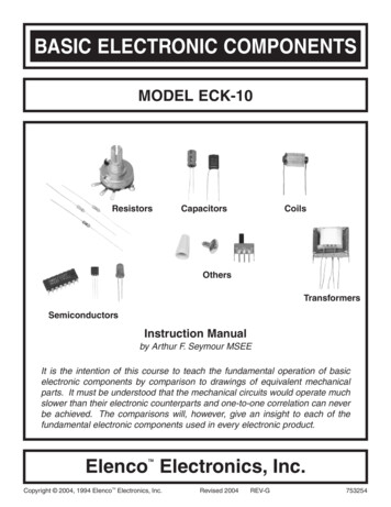
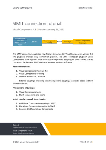
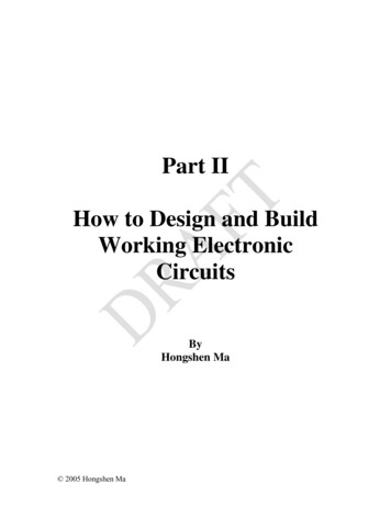
Familiarisation of Electronic Components and Equipments4Thick Film ResistorsThe production method of Thick film resistors is same like thin film resistors, but the difference isthat there is a thick film instead of a thin film or layer of resistive material around. That’s why it iscalled Thick film resistors. b) Variable ResistorsWhen a resistor is constructed so its value can be adjusted, it is called a variable resistor. Figurebelow shows the basic elements present in all variable resistors. First a resistive material isdeposited on a non-conducting base. Next, stationary contacts are connected to each end of theresistive material. Finally, a moving contact or wiper is constructed to move along the resistivematerial and tap off the desired resistance. There are many methods for constructing variableresistors, but they all contain these three basic principles.Fig: Variable Resistor2. Non Linear ResistorsWe know that, nonlinear resistors are those resistors, where the current flowing through itdoes not change according to Ohm’s Law but, changes with change in temperature or appliedvoltage.In addition, if the flowing current through a resistor changes with change in bodytemperature, then these kinds of resistors are called Thermisters. If the flowing current through aresistor change with the applied voltages, then it is called a Varistors or VDR (Voltage DependentResistors).Following are the different types of Non Linear Resistors.1.Thermisters2.Varisters(VDR)3. Photo Resistor or Photo Conductive Cell or LDR
Familiarisation of Electronic Components and Equipments5ThermistorsThermistors are thermally sensitive resistors whose prime function is to exhibit a large,predictable and precise change in electrical resistance when subjected to a corresponding change inbody temperature. Thermisters are made from the cobalt, Nickel, Strontium and the metal oxides ofManganese.Negative Temperature Coefficient (NTC) thermistors exhibit a decrease in electricalresistance when subjected to an increase in body temperature and Positive Temperature Coefficient(PTC) thermistors exhibit an increase in electrical resistance when subjected to an increase in bodytemperature.When thermistor is subjected to a temperature change,the resistance of the thermistorchanges.This change in resistance become a measure of the change in temperature whencalibrated.Fig: Thermistor SymbolVaristorsVaristors are voltage dependent Resistors (VDR) which is used to eliminate the high voltagetransients. In other words, a special type of variable resistors used to protect circuits fromdestructive voltage spikes is called varistors. When voltage increases (due to lighting or line faults)across a connected sensitive device or system, then it reduces the level of voltage to a secure leveli.e. it changes the level of voltages.Photo Resistor or Photo Conductive Cell or LDR (Light Dependent Resistors)Photo Resistor or LDR (Light Dependent Resistors) is a resistor which terminal value ofresistance changes with light intensity. In other words, those resistors, which resistance valueschanges with the falling light on their surface is called Photo Resistor or Photo Conductive Cell orLDR (Light Dependent Resistor). The material which is used to make these kinds of resistors is calledphoto conductors, e.g. cadmium sulfide, lead sulfide etc.When light falls on the photoconductive cells (LDR or Photo resistor), then there is anincrease in the free carriers (electron hole pairs) due to light energy, which reduce the resistance of
Familiarisation of Electronic Components and Equipments6semiconductor material (i.e. the quantity of light energy is inversely proportional to thesemiconductor material). It means photo resistors have a negative temperature coefficient.Fig: Light Dependent Resistor (LDR)Resistor MarkingMarkings on resistors can vary. Larger resistors have printed resistance values, while smallerresistors have color-coded bands. The correspondence between the digits and the colors of thebands is named resistor color code. This code is used to determine the value of a resistor or indicateits values by using a color code. It is defined by the international standard “IEC 60062” entitled‘Marking codes for resistors and capacitors’. To determine the resistance of a colour-coded resistor,start from the end opposite the silver or gold band. Use the colour code chart shown in table todetermine the resistance values.There are three types of resistors depending on the number of bands: 4-band, 5-band and 6-bandresistors.4-band resistorsIn 4-band resistors, the first two bands identify the first and second digits of the resistance value,and the third band indicates the number of zeroes. The fourth determines the tolerance of theresistor that indicates the incertitude on the effective value of the resistor given by themanufacturer. The selling price of the resistor is inversely proportional to its precision.
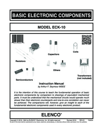
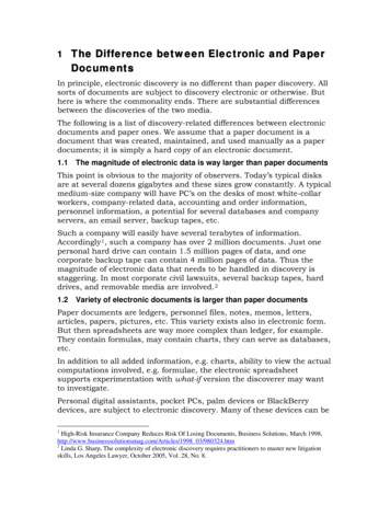
7Familiarisation of Electronic Components and EquipmentsBandValue Band colour & its tolerancecolourBlack0Gold 5%Brown1Silver 10 %Red2No colour means 20 %Orange3Yellow4Green5Blue6Violet7Grey8White9Table: Colour Code ChartFigure: Four Band ResistorFor example,refer the four band resistor shown below. Where, brown 1, black 0, red 2(10 2)and silver 10 % tolerance. Hence its value is 10 x 10 2 Ω 1000 Ω 1 k Ω.
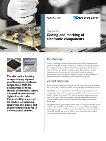
Familiarisation of Electronic Components and Equipments8CapacitorsThe Capacitor, sometimes referred to as Condenser, is a simple passive element that is used to‘store electricity’. The capacitor is a component which has the ability or ‘capacity’ to store energy inthe form of an electrical charge producing a potential difference across its plates, much like a smallrechargeable battery.A Capacitor consists of two or more parallel conductive (metal) plates which are not connected ortouching each other, but are electrically separated either by air or by some form of a good insulatingmaterial such as waxed paper, mica, ceramic, plastic or some form of a liquid gel as used inelectrolytic capacitors. The insulating layer between capacitor plates is commonly calledthe Dielectric.By applying a voltage to a capacitor and measuring the charge on the plates, the ratio of the chargeQ to the voltage V will give the capacitance value of the capacitor and is therefore given as: C Q/V.This equation can also be re-arranged to give the more familiar formula for the quantity of chargeon the plates as; Q C x V. The property of a capacitor to store charge on its plates in the form of anelectrostatic field is called the Capacitance of the capacitor. The capacitance is given by C ε0 εr A /d, where A is the area of plates, d is the plates separation, ε0 is the permittivity of free space ( 8.84x 10⁻¹² F/m ) and εr is the relative permittivity of the material being used as the dielectric .Fig: Operational Diagram of a CapacitorThe conductive plates of a capacitor are generally made of a metal foil or a metal filmallowing for the flow of electrons and charge, but the dielectric material used is always an insulator.The various insulating materials used as the dielectric in a capacitor differ in their ability to block orpass an electrical charge.
Familiarisation of Electronic Components and Equipments9This dielectric material can be made from a number of insulating materials or combinationsof these materials with the most common types used being: air, paper, polyester, polypropylene,Mylar, ceramic, glass, oil, or a variety of other materials.Capacitance is defined as being that a capacitor has the capacitance of One Farad when a chargeof One Coulomb is stored on the plates by a voltage of One volt. Capacitance, C is always positiveand has no negative units. However, the Farad is a very large unit of measurement to use on its ownso sub-multiples of the Farad are generally used such as micro-farads, nano-farads and pico-farads. Microfarad (μF) 1μF 10-6 F Nanofarad (nF) 1nF 10-9 F Picofarad (pF) 1pF 10-12 FFig: Capacitor SymbolsThere are three main classes of capacitors: (i) Non electrolytic or normal capacitors and (ii)electrolytic capacitors and (iii) variable capacitors.(i)Non electrolytic capacitorsNon electrolytic capacitors are mostly of parallel plate type and can have mica, paper, ceramic orpolymer as dielectric.Mica CapacitorsMica capacitors are made from plates of Aluminium foil separated by sheets of mica. Theplates are connected to two electrodes. The mica capacitors have excellent characteristics understress of temperature variations and high voltage applications ( 500 V). Available capacitances rangefrom 5 to 10,000 pF. Its leakage current is very small (Rleakage is about 1000 MW).
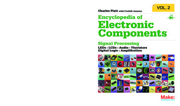
Familiarisation of Electronic Components and Equipments10Fig: Construction of a Mica CapacitorCeramic CapacitorsCeramic capacitors are made in many shapes and sizes. A ceramic disc is coated on two sideswith a metal, such as copper or silver. These coatings act as two plates. After attaching tinned-wireleads, the entire unit is coated with plastic and marked with its capacitance value—either usingnumerals or colour code. The colour coding is similar to that used for resistances. Ceramic capacitorsare very versatile. Their working voltage ranges from 3 V (for use in transistors) up to 6000 V. Thecapacitance value ranges from 3 pF to about 3 mF. Ceramic capacitors have a very low leakagecurrent (Rleakage is about 1000 MW) and can be used in both dc and ac circuits.Fig: construction of a Ceramic CapacitorPaper CapacitorsThis capacitor consists of two metal foils separated by strips of paper. This paper is impregnatedwith a dielectric material such as wax, plastic or oil. Since paper can be rolled between two metalfoils, it is possible to concentrate a large plate area in a small volume. Paper capacitors havecapacitances ranging from 0.0005 mF to several mF, and are rated from about 100 V to severalthousand volts. They can be used for both dc and ac circuits. Its leakage resistance is of the order of100 MW.
Familiarisation of Electronic Components and Equipments11Fig: Construction of a Paper Capacitor(ii)Electrolytic CapacitorsAn electrolytic capacitor consists of an aluminium-foil electrode which has an aluminiumoxide film covering on one side. The aluminium plate serves as the positive plate and the oxide asthe dielectric. The oxide is in contact with a paper or gauze saturated with an electrolyte. Theelectrolyte forms the second plate (negative) of the capacitor. Another layer of aluminium withoutthe oxide coating is also provided for making electrical contact between one of the terminals and theelectrolyte. In most cases, the negative plate is directly connected to the metallic container of thecapacitor. The container then serves as the negative terminal for external connections.The aluminium oxide layer is very thin. Therefore, the capacitor has a large capacitance in asmall volume. It has high capacitance-to-size ratio. It is primarily designed for use in circuits whereonly dc voltages are applied across the capacitor. The terminals are marked ve and –ve. Ordinaryelectrolytic capacitors cannot be used with alternating currents. However, there are capacitorsavailable that can be used in ac circuits (for starting motors) and in cases where the polarity of the dcvoltage reverses for short periods of time. The capacitance value may range from 1 mF to severalthousand microfarads. The voltage ratings may range from 1 V to 500 V, or more.Fig: Construction of Electrolytic Capacitor
Familiarisation of Electronic Components and Equipments12Electrolytic Capacitors are generally used in DC power supply circuits due to their largecapacitance’s and small size to help reduce the ripple voltage or for coupling and decouplingapplications. One main disadvantage of electrolytic capacitors is their relatively low voltage ratingand due to the polarisation of electrolytic capacitors, it follows then that they must not be used onAC supplies. Electrolytic’s generally come in two basic forms; Aluminium ElectrolyticCapacitors and Tantalum Electrolytic Capacitors.(iii) Variable CapacitorsA Variable Capacitor is one whose capacitance may be intentionally and repeatedly changedmechanically. Variable capacitors are often used in L/C circuits to set the resonance frequency, forexample, to tune a radio (therefore they are sometimes called tuning capacitors), or as a variablereactance for impedance matching in antenna tuners. The most common variable capacitor is theair-gang capacitor. The dielectric for this capacitor is air. By rotating the shaft at one end, we canchange the common area between the movable and fixed set of plates. The greater the commonarea, the larger the capacitance.In some applications, the need for variation in the capacitance is not frequent. One setting issufficient for all normal operations. In such situations, we use a variable capacitor called a trimmer(sometimes called padder). Both mica and ceramic are used as the dielectric for trimmer capacitors.Fig: Construction of a Mica TrimmerColour and Number code of capacitorsDifferent marking schemes are used for electrolytic and non-electrolytic capacitors.Temperature coefficient is of minor importance in an electrolytic filter capacitor, but it is veryimportant in ceramic trimmers for attenuator use. One never finds temperature coefficient on anelectrolytic label, but it is always present on ceramic trimmers.(i) Electrolytic Capacitors
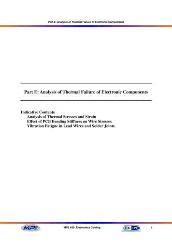
Familiarisation of Electronic Components and Equipments13There are two designs of electrolytic capacitors: (i) Axial where the leads are attached to eachend (220µF in picture) and (ii) Radial where both leads are at the same end (10µF in picture).Fig: Axial and Radial Electrilytic Capacitors(ii) Non-polarised capacitors ( 1µF)Small value capacitors have their values printed but without a multiplier. For example 0.1means 0.1µF 100nF. Sometimes the unit is placed in between 2 digits indicating a decimalpoint. For example: 4n7 means 4.7nF.Fig: Examples of Number Coded CapacitorsInductorsInductors are the passive components consisting of coils of insulated copper wire woundaround a former that will have some type of core at its centre. This core might be a metal such asiron that can be easily magnetised; or in high frequency inductors, it will more likely to be just air.Inductors resist or oppose changes of current but will easily pass a steady state DC current.This ability of an inductor to resist changes in current and which also relates current, i with its
Familiarisation of Electronic Components and Equipments14magnetic flux linkage, Nφ as a constant of proportionality is called Inductance which is given thesymbol L . Inductance of a coil is measured in Henry’s. This name comes from an outstandingscientist by the name of Joseph Henry who studied coils and their properties in the early days ofelectronics. One Henry is the amount of inductance required to produce an e.m.f. of 1 volt in aconductor when the current in the conductor changes at the rate of 1 Ampere per second. Typically,milli Henry’s or even micro Henry’s are used to measure inductance. Large power transformers inpower substation may have 1000 Henry’s or more of inductance.Fig: Inductor BasicsTransformersTransformer is a static device which transforms electrical energy from one circuit to anotherwithout any direct electrical connection and with the help of mutual induction between twowindings. It transforms power from one circuit to another without changing its frequency but maybe in different voltage level. Transformers are commonly used in applications which require theconversion of AC voltage from one voltage level to another.There are two broad categories of transformers: electronic transformers, which operate atvery low power levels, and power transformers, which process thousands of watts of power.Electronic transformers are used in consumer electronic equipment like television sets, CD players,personal computers, and many other devices, to reduce the level of voltage from 220V (availablefrom the AC mains) to the desired level at which the device operates. Power transformers are usedin power generation, transmission and distribution systems to raise or lower the level of voltage tothe desired levels. The basic principle of operation of both types of transformers is the same.
15Familiarisation of Electronic Components and EquipmentsWorking Principle of TransformerTransformer works on the principle of mutual induction of two coils or Faraday Law’s OfElectromagnetic induction. Faraday’s law states that a voltage appears across the terminals of anelectric coil when the flux linkages associated with the same changes. This emf is proportional to therate of change of flux linkages.e dφ/dt . (1)Where, e is the induced emf in volt and φ is the flux linkages in Weber turn.Fig:Basic Structure of a TransformerThe figure shows the simplest form of a transformer. Basically a transformer consists of twoinductive coils; primary winding and secondary winding. The coils are electrically separated butmagnetically linked to each other. When, primary winding is connected to a source of alternatingvoltage, alternating magnetic flux is produced around the winding.The core provides magnetic path for the flux, to get linked with the secondary winding. Mostof the flux gets linked with the secondary winding. As the flux produced is alternating,emf getsinduced in the secondary winding according to Faraday's law of electromagnetic induction. This emfis called 'mutually induced emf', and the frequency of mutually induced emf is same as that ofsupplied emf. If the secondary winding is closed circuit, then mutually induced current flows throughit, and hence the electrical energy is transferred from one circuit (primary) to another circuit(secondary).
Familiarisation of Electronic Components and Equipments16Types of TransformersThe transformers are classified based on voltage levels, design, Core medium used,windingarrangements and the type of cooling employed.Transformers based on voltage levelsThe transformers are classified as step-up and step-down transformers as the voltage ratios fromprimary to secondary. These are widely used transformer types for all the applications. Here theimportant thing to remember is that there will not be any difference in primary power andsecondary power. That means if the voltage is high at secondary side then the current drawn fromthe secondary will low so that the power will be same. Same as in the reverse case when the voltageis low the current drawn will be high.Step-up transformerAs the name specifies the secondary voltage is stepped up with a ratio compared to primaryvoltage. This is achieved by increasing the number of coil turns in the secondary as shown in figure.In power plant this transformer is used as connecting transformer of Generator to Grid. TheGenerated low voltage should be suitably stepped up to connect to high voltage grid.Step-down transformerIn this transformer the voltage is stepped down at the secondary from high voltage primary so that itis called as step-down transformer. The winding turns will be high at primary side where as it willless at secondary side. In power plant the use of this transformer are very high where the grid powersupply stepped down and given to corresponding plant auxiliaries during starting of the powerplant. Once the plant has started then the voltage stepping down is necessary where the plantauxiliaries will operate at low voltage compared to its generated voltage. In distribution also the stepdown transformer is widely used to convert the high grid voltage to the low voltage which can beused at house purposes.
Familiarisation of Electronic Components and Equipments17PN Junction DiodeDiode is a two terminal device consisting of a PN junction formed either in Ge or Si crystal.Here the terminal on the P-side is called the anode and the terminal on the N-side is called thecathode. In the symbol of the diode anode is identified by large arrow. The forward current directionin the diode is in the direction of the arrow(ie,from P to N).The PN junction conducts the currentonly when it is in forward biased and no current flows through it when it is in reverse biased(i.e.,current flows in only one direction). Thus the diode is called uni directional device.Types of diodesWe can distinguish the following types of diodes: Rectifier diodes are typically used for power supply applications. Within the power supply, you willsee diodes as elements that convert AC power to DC power. Switching diodes have lower power ratings than rectifier diodes, but can function better in highfrequency application and in clipping and clamping operations that deal with short-duration pulsewaveforms.A number of special purpose diodes for specific applications in this fast developing world. Some ofthe more common special-purpose diodes are (a) Zener diode (b) Light-emitting diode (LED) (c)Photo-diode (d) Tunnel diode (e) Varactor diode and solar sells.
Familiarisation of Electronic Components and Equipments18Zener DiodesZener diodes are also called breakdown diodes. These are specially doped PN junction diodesto produce controlled break down characteristics without damage and are operated in the breakdown region. The break down in zener diode is influenced by two phenomenon, zener effect andavalanche effect. Here zener effect is predominant for break down voltages less than about 4V andavalanche break down is predominant for voltages greater than 6V.Between 4V and 6V, both effectsare present. Because of high temperature and current capability, Silicon is usually preferred for themanufacture of zener diodes. The break down voltage Vz and resistance Rz of zener diode iscontrolled by varying the doping level of the PN junction. Increasing the impurity will decrease bothbreak down voltage and resistance.Light Emitting Diode (LED):Light emitting diode is a PN junction that emits optical radiation generated by therecombination of electrons and holes, when the junction is forward biased. Most of the commercialLEDs are realized using a highly doped N and a P Junction.Photo-diodeA photo-diode is a reverse-biased silicon or germanium pn junction in which reverse currentincreases when the junction is exposed to light. The reverse current in a photo-diode is directlyproportional to the intensity of light falling on its pn junction. This means that greater the intensityof light falling on the pn junction of photo-diode, the greater will be the reverse current.
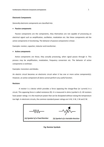
Familiarisation of Electronic Components and Equipments19Varactor DiodeThese are also known as Varicap diodes. It acts like the variable capacitor. Operations areperformed mainly at reverse bias state only. These diodes are very famous due to its capability ofchanging the capacitance ranges within the circuit in the presence of constant voltage flow. They canable to vary capacitance up to high values. In varactor diode by changing the reverse bias voltage wecan decrease or increase the depletion layer. These diodes have many applications as voltagecontrolled oscillator for cell phones, satellite pre-filters etc. The symbol of varactor diode is givenbelow.Fig: Symbol of a Varactor DiodeTransistorsThe transistor is the main building block “element” of electronics. It is a semiconductordevice and it comes in two general types: the Bipolar Junction Transistor (BJT) and the Field EffectTransistor (FET).Bipolar Junction Transistor (BJT)Bipolar Junction Transistor is a three terminal active device which transforms current flowfrom low resistance path to high resistance path. This transfer of current through resistance path,given the name to the device ‘transfer resistor’ as transistor. Transistors consists of junctions withinit, are called junction transistors. The bipolar junction transistor (BJT) is a three terminal deviceconsists of two P-N junctions connected back to back. Current carries inside is by two oppositepolarities of charge carriers (electrons and holes), hence the name bipolar junction transistor.If a P-type material is sandwiched between two N-type materials as shown in fig (a), theresulting structure is called NPN transistor. Similarly when N-type material is sandwiched betweenthe two P-type materials as shown in fig (b), the resulting structure is called PNP transistor. In both
Familiarisation of Electronic Components and Equipments20cases, the first layer where the emission or injection of the carriers starts is called emitter. Thesecond layer through which carriers passes is called the base and the third layer which collects theinjected carriers is called collector. In the symbol, the emitter has an arrowed head; it points thedirection of the conventional emitter current (from P to N region).Although the emitter and collector are same type of material, they have different physicaland electrical properties. The collector section is physically larger than the emitter section, since ithas to collect all injected carriers and to withstand the large reverse bias voltage. The base is verythin and lightly doped. The size of the emitter falls between the base and collector region and isheavily doped. The doping level of colle
Familiarisation of Electronic Components and Equipments 8 Capacitors The Capacitor, sometimes referred to as Condenser, is a simple passive element that is used to ‘store electricity’. The capacitor is a component which has the ability or ‘capacity’ to store energy in the form of