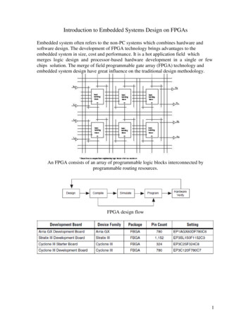
Transcription
Embedded System Design:Concepts and ToolsDaniel D. GajskiAndreas GerstlauerSamar AbdiCenter for Embedded Computer SystemsUniversity of California, IrvineASPDAC’07 TutorialOutline Requirements Modeling Verification and synthesis Summary, conclusions and outlookASPDAC’07 TutorialCopyright 2007 CECS1
Embedded System Design:RequirementsDaniel D. GajskiCenter for Embedded Computer SystemsUniversity of California, IrvineASPDAC’07 TutorialOutline Requirements Issues Models Platforms Tools Modeling Verification and synthesis Summary, conclusions and outlookASPDAC’07 TutorialCopyright 2007 CECS2
Closing the System GapReal gap: behavior and structure (semantics and syntax)ASPDAC’07 TutorialCopyright 2007 CECSSimulation Based MethodologyAmbiguous semantics of hardware/system level languagesSimulatable but not synthesizable or verifiableASPDAC’07 TutorialCopyright 2007 CECS3
In Search of a SolutionAlgebra: objects, operations Arithmetic algebra allows creationof expressions and equivalencesASPDAC’07 TutorialCopyright 2007 CECSModel AlgebraModel algebra: objects, compositions Model algebra allows creation of models and model equivalencesASPDAC’07 TutorialCopyright 2007 CECS4
Specify-Explore-Refine MethodologyDesign decisionsModel refinementReplacement orre-compositionFPGA boardCopyright 2007 CECSASPDAC’07 TutorialGeneral System Design EnvironmentModel ooltiModel BASPDAC’07 TutorialCopyright 2007 CECS5
How many models?Minimal set for any methodology(Are 3 enough ?) System specification model (application designers) Transaction-level model (system designers) Pin&Cycle accurate model (implementation designers)Copyright 2007 CECSASPDAC’07 TutorialThree Models (with Respect to OSI)Pin / Cycle Accurate ModelTransaction Level ModelSpecification workSpec2b. Link Stream2a. Media Access CtrlApplication2b. Link StreamTLM2a. Protocol1.7.2a. Media Access Ctrl2a. ProtocolPhysical1.PhysicalAddress linesData linesControl linesP/CAMSource: G SchirnerASPDAC’07 TutorialCopyright 2007 CECS6
How many components?Minimal set for any design(Are 4 enough?) Processing element (PE) Memory Transducer / Bridge ArbiterCopyright 2007 CECSASPDAC’07 TutorialGeneral System ModelArbiter 2Arbiter 1Interrupt2.1PE 2.1(Master)Interrupt1.1PE 1.1Transducer1-2Interrupt2.2PE 2.2(Slave)Arbiter 3PE 1.2PE 3.1Interrupt3.1Interrupt3.2Transducer2-3Memory 1Memory 3Bus1ASPDAC’07 TutorialBus2Bus3Copyright 2007 CECS7
How many tools?Minimal set for any methodology(Are 2 enough?) Front-End (for application developers)–Input:C, C , Mathlab, UML, –Output:TLMBack-End (for SW/HW system designers)–Input :TLM–Output:Pin/Cycle accurate Verilog/VHDLCopyright 2007 CECSASPDAC’07 TutorialES rInterface(VUI)CompilerESE Front – EndCreateDebuggerSystem Capture Platform ompileCYCLEACCURATEReplaceESE Back – EndCompileSW Development HW DevelopmentCheckSimulateVerifyApplication Tools : Compilers/DebuggersASPDAC’07 TutorialCommercial Tools : FPGA, ASICCopyright 2007 CECS8
Does it work? Intuitively it does– Well defined models, rules, transformations, refinements– Worked in the past: layout, logic, RTL?– System level complexity simplified Following talks will prove the concept––––ES modeling abstractionsAutomatic model generationModel synthesis and verificationEmbedded System Environment (ESE)Copyright 2007 CECSASPDAC’07 TutorialOutline9 Requirements9 Issues9 Models9 Platforms9 Tools Modeling Verification and synthesis Summary, conclusions and outlookASPDAC’07 TutorialCopyright 2007 CECS9
Embedded System Design:ModelingAndreas GerstlauerCenter for Embedded Computer SystemsUniversity of California, Irvinehttp://www.cecs.uci.edu/pub slidesASPDAC’07 TutorialOutline Requirements Modeling Introduction Languages and models System modeling semantics Automatic model generation Design example Tools Summary and conclusions Verification and synthesis Summary, conclusions and outlookASPDAC’07 TutorialCopyright 2007 CECS10
Introduction Growing SoC complexities and sizes Heterogeneous multi-processor SoC (MPSoC) Networked, distributed systems¾ System modeling Validation and analysis Concurrent hardware/software development Specification for further implementation/synthesis¾ Higher levels of abstraction for speed/accuracytradeoffs¾ Rapid, early design space explorationCopyright 2007 CECSASPDAC’07 TutorialSystem Modeling Abstraction based on level of detail/granularity Computation Communication¾ System-level design flow¾ Path from model A to model UntimedFEA. System specification modelB. Component modelC. Bus-arbitration modelD. Bus-functional modelE. Cycle-accurate computation modelF. RTL/ISS Implementation modelBApproximatetimedCycletimedComputationSource: Lukai Cai, D. Gajski. “Transaction level modeling: An overview”, ISSS 2003ASPDAC’07 TutorialCopyright 2007 CECS11
System Design Languages Netlists Structure only: components and connectivity¾ Gate-level [EDIF], system-level [SPIRIT/XML] Hardware description languages (HDLs) Event-driven behavior: signals/wires, clocks Register-transfer level (RTL): boolean logic¾ Discrete event [VHDL, Verilog] System-level design languages (SLDLs) Software behavior: sequential functionality/programs¾ C-based [SpecC, SystemC, SystemVerilog]ASPDAC’07 TutorialCopyright 2007 CECSESL Modeling Today Simulation-centric system modeling Co-simulation at lower RTL/ISS levels [Axys, VaST]– CPU-centric, limited architectures/designs [ARM] Transaction-level models [CoWare, Summit]– Multi-processor system simulation [SystemC]– Graphical platform assembly [Eclipse]– Processor customization [Tensilica, Lisatek] Algorithmic specification [SPW, MATLAB, COSSAP]– Varying models of computation (MoC) [Ptolemy]– Model-based design [UML, MATLAB/Simulink]¾ Horizontal integration of different models / components¾ Lack vertical integration for synthesis-centric approachASPDAC’07 TutorialCopyright 2007 CECS12
System Modeling Needs Language ambiguities Simulation vs. synthesis (subsets) Impossible to automatically discern implicit meaning¾ Well-defined, rigorous semantics Unambiguous, explicit abstractions, models– Objects and composition rules– Computation and communication Systematic flow from specification to implementation– Transformations and refinements¾ Reliable feedback at early stages¾ Design automation for synthesis, verification¾ Rapid, early design space explorationCopyright 2007 CECSASPDAC’07 TutorialOutline Requirements Modeling Introduction Languages and models System modeling semantics Automatic model generation Design example Tools Summary and conclusions Verification and synthesis Summary, conclusions and outlookASPDAC’07 TutorialCopyright 2007 CECS13
Computation ModelingProcess B1(){ waitfor(15000); waitfor(25000); }; Application modeling Native process execution (C code) Back-annotated execution timingCPU Processor modeling Operating systemB1B2– Real-time multi-tasking (RTOS model)– Bus drivers (C code)OSHAL Drv ISR Hardware abstraction layer (HAL)– Interrupt handlers– Media accesses Processor hardwareBus– Bus interfaces (I/O state machines)– Interrupt suspension and timingInterruptsSource: G. Schirner, A. Gerstlauer, R. Doemer. “Abstract, Multifaceted Modeling of Embedded Processors for System Level Design,” ASPDAC, 2007.Copyright 2007 CECSASPDAC’07 TutorialRTOS Modeling High-level RTOS abstraction Wrap around SLDL primitives, replace event TOS Comm. & Sync. APIChannelsRTOS – High-level, abstract model– Target-independent, canonical API– Small overhead, low complexityApplicationB1 Dynamic scheduling behaviorB2B3B4B5RTOSModel– Real-time scheduling, multi-tasking– Preemption, interrupt handlingCPU HW Model IPC channelsSLDL– Task communication, synchronizationSource: A. Gerstlauer, H. Yu, D. Gajski. "RTOS Modeling for System-Level Design," DATE, 2003.ASPDAC’07 TutorialCopyright 2007 CECS14
Communication Modeling¾ SoC communication ApplicationChannels, -end typed messagesData formattingApplication6End-to-end untyped messagesSynchronization,MultiplexingOS kernel5TransportEnd-to-end data streamsPacketing, Flow control,Error correctionOS kernel4NetworkEnd-to-end packetsRoutingOS kernel3Point-to-point logical linksStation typing,SynchronizationDriver2bStreamPoint-to-point control/data streamsMultiplexing,AddressingDriver2bMedia AccessShared medium byte streamsData slicing,ArbitrationHAL2aSessionLinkProtocolMedia (word/frame) transactionsProtocol timingHardware2aPhysicalPins, wiresDriving, samplingInterconnect1Source: A. Gerstlauer, D. Shin, R. Dömer, D. Gajski, "System-Level Communication Modeling for Network-On-Chip Synthesis," ASPDAC, 2005.Copyright 2007 CECSASPDAC’07 TutorialTransaction-Level ModelingPin / Cycle Accurate ModelTransaction Level ModelSpecification workSpec2b. Link Stream2a. Media Access CtrlApplication2b. Link StreamTLM2a. Protocol1.7.2a. Media Access Ctrl2a. ProtocolPhysical1.PhysicalAddress linesData linesControl linesP/CAMSource: G. SchirnerASPDAC’07 TutorialCopyright 2007 CECS15
Modeling ResultsSimulation Time [s]100000100001000MP3JPEGGSM1001010.10.01Spec.TLM (Net)TLM (Prot)PAMCAMAverage Error [%]25MP3JPEGGSM20151050Spec.TLM (Net)TLM (Prot)PAMCAMSource: G. Schirner, A. Gerstlauer, R. DoemerCopyright 2007 CECSASPDAC’07 TutorialOutline Requirements Modeling Introduction Languages and models System modeling semantics Automatic model generation Design example Tools Summary and conclusions Verification and synthesis Summary, conclusions and outlookASPDAC’07 TutorialCopyright 2007 CECS16
Automatic Model Generation Problem: Writing of system models is Time consuming, error-prone, tedious Solution: Automatic model generation Refinement-based approach System designer : makes design decisions Refinement tool : automatically generates the model Benefits No manual model writing, focus on design decisions Low error rate by automating error-prone tasks Easy change/upgrade for incremental/derivative design No change in basic design methodology¾ Enables fast, extensive design space exploration¾ Productivity gains (1000x)¾ Shorter time-to-marketCopyright 2007 CECSASPDAC’07 TutorialESL Design FlowPlatform ArchitecturePlatform Services/ApplicationSystem tware)(Hardware/Software)Back-EndBack-EndObject CodeASPDAC’07 TutorialSystemCInstruction-Set ront-EndVHDL/Verilog RTLCopyright 2007 CECS17
Platform ro(Custom)MSMSTXArbiter1M1CtrlBUS1 (AHB)ArbBUS2 I/O4(HW)IP BridgeMDCTBusSDCT(IP) Components ConnectivityProcessorsMemoriesIPsCustom HW BusesBridgesPortsCopyright 2007 CECSASPDAC’07 TutorialPlatform ServicesApplicationARMM1DSPv1v2JpegHWEnc Dec15MBUS10CodebkRTOSM1CtrlTXArbiter1Test codeBUS1 (AHB)IP BridgeBUS2 (DSP)I/O1DMASIDCTBusI/O2BOI/O3I/O4BISODCTv3DCT Computation ASPDAC’07 TutorialProcesses (hierarchical C)Scheduling (static/OS)Copyright 2007 CECS18
Platform ServicesM1DSP0x400x48HWEnc DecCodebk0x0C00,intCMBUSC3C40x0C50,intCint0IP BridgeI/O1DMASIDCTBusC7I/O2I/O3BOC8BUS2 t1BUS1 ARMI/O4BISO0x80DCTv3DCT Computation Processes (hierarchical C)Scheduling (static/OS) Communication High-level IPC (channels)Storage (variables)Copyright 2007 CECSASPDAC’07 TutorialModel Generation Process Synthesis Decision making model elModel nModel nOptim.Optim.algorithmalgorithmDesign decisionsRefinementRefinementLibLibModelModeln 1n 1Implementation modelImplementation model¾ Successive model refinement¾ Layers of implementation detailASPDAC’07 TutorialCopyright 2007 CECS19
Specification ModelDMASerInBIDSP OSRcvDataSIDSPARM7MemSpchInCtrlARM ocessOSModelBOSerOutDCTSODCT IPSpchOutCopyright 2007 CECSASPDAC’07 TutorialTransaction-Level Model (Network)linkBIlinkBriBIlinkBriSBI HWBridgeDMADSP OSMDMA HWlinkDMASlinkSISIDSPMSI HWDCTAdapterMemlinkHWHWARM7ARM OSllinkBOOSModelBODCTBO HWDCT IPlinkSOSO Data conversion, channel mergingTransducer insertion, Packeting, RoutingASPDAC’07 TutorialSO HWCopyright 2007 CECS20
Transaction-Level Model (Protocol)POLL ADDRADDRADDRmacahbProtocolmacmacSI HWHW HWARM7polli semaphoreADDRT HWADDRADDRdspProtocoldspSlavememSIADDRDSP HALARM OSdspMasterADDRBI HWPOLL ADDRmacADDRmacADDRmemDSP OSDSPARM HALcfMastermemMem HWArbiterHWPOLL ADDRmacDCTBridgeBIpollcfSlaveDMADMA HWMemmacmacmacpollDCT IPintCintDBOBO HWpollPOLL ADDRADDRmacintBADDROSModelintA SOSO HWSynchronization, addressing, media accesArbitration, data slicing, interrupt handlingCopyright 2007 CECSASPDAC’07 TutorialBridgeADDRADDRPin-Accurate ModelADDRADDR,POLL ADDRDMABIDSP HALDSP OSSISI BFARM HALARM OSHW BFlADDRMemARM HWADDR,POLL ADDRADDRDSPARM BFDSP BFDSP HWADDRBI BFDMA BFMem BFHWDCT IPADDR,POLL ADDRlARM7ADDRADDRDCTPICBOT BFISROSModelBO BFPICArbiterADDR,POLL ADDRISRSOSO BF¾ Implementation synthesis in backend tools¾ Interface synthesis on hardware side¾ Bus driver and RTOS synthesis on the software sideASPDAC’07 TutorialCopyright 2007 CECS21
Outline Requirements Modeling Introduction Languages and models System modeling semantics Automatic model generation Design example Tools Summary and conclusions Verification and synthesis Summary, conclusions and outlookCopyright 2007 CECSASPDAC’07 TutorialExample: MP3 Decoder Functional block diagram (major blocks only)2 granulesAliasRedIMDCTFilterCoreLeft t channel Timing constraints 38 frames per second Frame delay 26.12msASPDAC’07 TutorialCopyright 2007 CECS22
System Definition Components allocated from database Bridge used to interface two busses Hierarchical processes inside PEs Parallel, sequential, leaf (C code) Channels and variables between CTFilterCorereal MPCMCopyright 2007 CECSASPDAC’07 TutorialOutput: Transaction-Level Model CMASPDAC’07 TutorialCopyright 2007 CECS23
TLM Simulation Timed-simulation Computation delays back-annotated in processes Communication delays modeled in the bus channels Simulation of TLM Functionally correct but frame delay far exceeds timing constraintCopyright 2007 CECSASPDAC’07 TutorialComputation Analysis View computation time of processes FilterCore is the most computation-intensiveDecodeMP3 tim e distributionARMARMv7Progranule tim e distributionChannel tim e distributionComm.View imdctrightchannelComm.left channelaliasredfiltercore Look for parallelism in process hierarchy FilterCore processes are running in parallel Use two identical custom HWsASPDAC’07 TutorialCopyright 2007 CECS24
System Modifications Add two more PEs: HW1 and HW2 Connect HW1 and HW2 to the mainBus Move processes from ARM to HWs Channels are automatically edIMDCTch3HuffEncFilterCorereal FilterCorepcmBusBridge.PCMCopyright 2007 CECSASPDAC’07 TutorialModified 7 TutorialPCMFilterCorePCMCopyright 2007 CECS25
Modified TLM Simulation Simulation of TLM Functionally correct Frame delay still violates timing constraintCopyright 2007 CECSASPDAC’07 TutorialCommunication Analysis Bus utilization graph Bus contention graphASPDAC’07 TutorialCopyright 2007 CECS26
More System Modifications Make two ports in HW1, HW2 Connect HWs directly to the DHS bus Remove the cmBusBridgech3IMDCTch2ArbiterAliasRedreal ch1ch0Copyright 2007 CECSASPDAC’07 TutorialModified ASPDAC’07 TutorialCopyright 2007 CECS27
Modified TLM Simulation Simulation of TLM Functionally correct Frame delay now meets timing constraintCopyright 2007 CECSASPDAC’07 TutorialOutline Requirements Modeling Introduction Languages and models System modeling semantics Automatic model generation Design example Tools Summary and conclusions Verification and synthesis Summary, conclusions and outlookASPDAC’07 TutorialCopyright 2007 CECS28
ELEGANT EnvironmentAnalog-to-digital decision emodelmodelRTLRTLHDLHDLBehavioral synthesisCyberSource: InterDesign Technologies, Inc.ASPDAC’07 TutorialCopyright 2007 CECSELEGANT Environment Complete ESL design environment Japanese Aerospace Exploration Agency (JAXA) Focus on correctness and reliability Integration of tools for simulation, synthesis, verification Specify-Explore-Refine (SER) tool 1st-generation of automatic model generation Top-down design– Specifiy desired system functionality– Explore architectural design alternatives– Refine specification into automatically generated TLM or PAMASPDAC’07 TutorialCopyright 2007 CECS29
Embedded Systems Environment face(VUI)CompilerESE Front – EndCreateDebuggerSystem Capture Platform ompileCYCLEACCURATEReplaceESE Back – EndCompileSW Development HW DevelopmentCheckSimulateVerifyApplication Tools : Compilers/DebuggersCommercial Tools : FPGA, ASICCopyright 2007 CECSASPDAC’07 TutorialES Environment (ESE) Next-generation ESL tool set ESE Front-End––––Platform capture and virtual prototyping (modeling, simulation)Embedded software development environmentCommunication network model (advanced TLM) generationHeterogeneous multi-processor SoC (MPSoC) target support ESE Back-End– Platform customization, optimization and implementation– Software and hardware synthesis– FPGA board prototypingASPDAC’07 TutorialCopyright 2007 CECS30
ESE: System DefinitionESE – atform1p1.scPlatform2p2.scp2 ltercorerightaliasredEdit source.imdctAdd childfiltercoreAdd channelBridgeuCosIIAdd variablemainBusAMBA sSRAM64SRAM128HardwaresHW StandardNISCPCMint process mode;c1 c double handshakei sendi receivec2 c handshakevoid antialias(real xr[SBLIMIT][SSLIMIT],struct gr info s *gr info){int sblim;}c3 c semaphoreif(gr info- block type 2){if(!gr info- mixed block flag)return;sblim 1;}else {sblim gr info- maxb-1;}void main(void){Outputscc: SpecC Compiler V 2.2.0(c) 1997-2005 CECS, University of California, IrvineReadyCopyright 2007 CECSASPDAC’07 TutorialESE: System ModificationsESE – orm1p1.scPlatform2p2.scp2 emainBusAMBA emoriesSRAM64SRAM128HardwaresHW StandardNISCChannelsHW1HW2PCMc1 c double handshakei sendi receivec2 c handshakec3 c semaphoreOutputReadyASPDAC’07 TutorialCopyright 2007 CECS31
ESE: System ModificationsESE – 1HW2PCMMainPlatform1p1.scPlatform2p2.scp2 ghtaliasredBridgeuCosIIimdctfiltercoremainBusAMBA UsARMv7MemoriesSRAM64SRAM128HardwaresHW StandardNISCHW1HW2c1 c double handshakei sendi receivec2 c handshakePCMConnectmainBusDisconnectpcmBusAdd port.masterCPUc3 c semaphoreslaveRemoveOutputReadyCopyright 2007 CECSASPDAC’07 TutorialESE: System ModificationsESE – orm1p1.scPlatform2p2.scp2 mdctfiltercorefiltercoremainBusAMBA emoriesSRAM64SRAM128HardwaresHW StandardNISCChannelsHW1HW2PCMc1 c double handshakei sendi receivec2 c handshakec3 c semaphorem1m2m3m4m5c double hc double hc double hc double hc double hOutputReadyASPDAC’07 TutorialCopyright 2007 CECS32
ESE: TLM SimulationESE – scp2 2.scPCMKill simulationleftView reBus ercore25%mainBusAMBA Channels3%CPUsARMv7 Simulation logMemoriesMP3DecoderSRAM64 Input MP3 file: funky.mp3SRAM128 Output file: funky.pcmHardwaresBitrate 96000 bits/s, Sampling frequency 44100 samples/sHW StandardFrame 1 . 10.67 msNISC Frame 2 . 21.33 msFrame 3 .PCMc1 c double handshakei sendi receivec2 c handshakeBus tracec3 c semaphoreOutputRunning simulation % xterm -e ./mp3decoder funky.mp3 funky.pcmReadyASPDAC’07 TutorialCopyright 2007 CECSSummary and Conclusions Technology advantages Platform can be easily captured using GUI TL models are automatically generated fordevelopment and testing of application code Legacy or preliminary SW can be easily captured andmapped to the platform ESL allows concurrent development of platform SW,HW and application code ESL allows easy upgrade of platform and reuse oflegacy application SW and RTL HW code¾ Early, rapid prototyping for design space exploration¾ Significant productivity gainsASPDAC’07 TutorialCopyright 2007 CECS33
References System-level languages and modeling T. Grötker, S. Liao, G. Martin, S. Swan. System Design with SystemC.Kluwer, 2002. A. Gerstlauer, R. Dömer, J. Peng, D. D. Gajski, System Design: APractical Guide with SpecC, Kluwer, 2001. F. Ghenassia. Transaction-Level Modeling with SystemC: TLM Conceptsand Applications for Embedded Systems, Springer, 2006.System prototyping and simulation L. Benini, D. Bertozzi, A. Bogoliolo, F. Menichelli, M. Olivieri. “MPARM:Exploring the Multi-Processor SoC Design Space with SystemC,”Journal of VLSI Signal Processing, Sept. 2005. T. Kempf, M. Dörper, R. Leupers, G. Ascheid, H. Meyr, T. Kogel, B.Vanthournout. “A Modular Simulation Framework for Spatial andTemporal Task Mapping onto Multi-Processor SoC Platforms,” DATEConference, March 2005.System-level design and design environments F. Balarin, H. Hsieh, L. Lavagno, C. Passerone, A. Pinto, A.Sangiovanni-Vincentelli, Y. Watanabe, G. Yang. “Metropolis: a DesignEnvironment for Heterogeneous Systems,” Multiprocessor Systems-onChips (Editors: W. Wolf, A. Jerraya), Morgan Kaufmann, 2004. A. A. Jerraya, F. Petrot, A. Bouchhima. “Programming Models and HWSW Interfaces Abstraction for Multi-Processor SoC,” DAC, June 2006. D. Gajski, A. Gerstlauer, R. Doemer, S. Abdi, J. Peng, D. Shin, R. Ang,"ESE Front End," http://www.cecs.uci.edu/pub slides, March 2006.Copyright 2007 CECSASPDAC’07 TutorialOutline9 Requirements9 Modeling Verification and synthesis Summary, conclusions and outlookASPDAC’07 TutorialCopyright 2007 CECS34
Embedded System Design:Verification and SynthesisSamar AbdiCenter for Embedded Computer SystemsUniversity of California, Irvinehttp://www.cecs.uci.edu/pub slidesASPDAC’07 TutorialOutline9 Requirements9 Modeling Verification and synthesis Existing verification methods TLM verification using transformations Issues in ES synthesis Synthesis of MP3 player design Results Summary, conclusions and outlookASPDAC’07 TutorialCopyright 2007 CECS35
Design Verification Methods Simulation based methods Specify input test vector, output test vector pair Run simulation and compare output against expected output Formal Methods Check equivalence of design models or parts of models Check specified properties on models Semi-formal Methods Specify inputs and outputs as symbolic expressions Check simulation output against expected expressionCopyright 2007 CECSASPDAC’07 TutorialSimulation Task : Create test vectors and simulate modelTools: VCS(Synopsys), ModelSim(Mentor), NC-Sim(Cadence)Inputs Specification– Typically natural language, incomplete and informal– Used to create interesting stimuli and monitors Model of DUT– Typically written in HDL or C or both Output Failed test vectors– Pointed out in different design representations by debugging toolsDUTMonitorsStimulusSpecificationTypical simulation environmentASPDAC’07 TutorialCopyright 2007 CECS36
Logic and FSM Equivalence Checkingoutputs121’2’Equivalenceresult1 1’ ?2 2’ ?outputsinputsinputs LEC uses boolean algebra to check for logic equivalence SEC uses FSMs to check for sequential equivalencex pay q bx ray sby txypsxx pr bpt xyaayx qrqsyybbqt yybbCopyright 2007 CECSASPDAC’07 TutorialModel Checking Model M satisfies property P? (Clarke, Emerson ’81) Inputs State transition system representation of M Temporal property P as formula of state properties Output True (property holds) False counter-example (property does not hold)P1s1s2s4s3P4MASPDAC’07 TutorialP3P2P P2 always leads to P4ModelCheckerTrue /False counter-exampleCopyright 2007 CECS37
New Verification Challenges for SoC Design Design complexity Size– Verification either takes unreasonable time (eg. Logic simulation)– Or takes unreasonable memory (eg. Model Checking) Heterogeneity– HW / SW components on the same chip– Interface problems Modeling abstraction– No formalism exists to prove equivalence of high level models– LEC and SEC are not applicable above RTL Possible directions Methodology– Unified HW/SW models– Model formalization– Automatic model transformationsASPDAC’07 TutorialCopyright 2007 CECSSystem Verification through Refinement Set of models Designer Decisions transformations Transformations preserve equivalence Same partial order of tasks Same input/output data for each task Same partial order of data transactions Equivalent replacementsModel A All refined models will be “equivalent” toinput modelStill need to verifyDesignerDecisionsLibrary ofobjectsRefinementToolt1t2 tmModel BFirst modelCorrectness of replacementsASPDAC’07 TutorialCopyright 2007 CECS38
Formal Model Representation Model Algebra {objects}, {composition rules} Objects Behaviors (for computation) Channels (for synchronized communication)Variables (for storage)Ports (for hierarchy / connections)b– Identity behaviors (output identical to input) q2ce1Control dependencyChannel transactionVariable read/writeq3Hierarchical behavior q1v1e2Composition rules b1v2b2Grouping of sub-behaviors, channels, variablesand their compositionsSystem Top level behaviorCopyright 2007 CECSASPDAC’07 TutorialRefinement Example Design decisionsMs Select PEs Map leaf behaviors to PEsb1b2 Resulting model refinement Additional hierarchy for PEs Distribute leaf behaviors inside PEs Add Identity behaviors and channelsto preserve control flow– Each PE has independent control Refinement verificationMaPE1PE2b1e2synce1b2 Express refinement as sequence ofmodel transformationsASPDAC’07 TutorialCopyright 2007 CECS39
Transformation Step 1q1q2b1b2b1eq1b2q2Identity Addition Ruleb1Mse1b1e2b2b2( Original Model )( Intermediate Model 1 )Copyright 2007 CECSASPDAC’07 TutorialTransformation Step 2e1e21e1synce2Channel Addition Ruleb1b1e1e1e2b2( Intermediate Model 1 )ASPDAC’07 Tutorialsynce2b2( Intermediate Model 2 )Copyright 2007 CECS40
Transformation Step 3bsyncbsyncHierarchy Addition Ruleb1e1MasyncPE1PE2b1e2e2synce1b2b2( Intermediate Model 2 )( Final Model )Copyright 2007 CECSASPDAC’07 TutorialSummary of ES Verification Variety of verification techniques available But they apply to traditional design flow based on RTL Challenges for verification of large system designs Simulation based techniques take way too long Most formal techniques cannot scale in size or abstraction level Future design and verification Well defined semantics for models at different abstraction levels Well defined transformations for design decisions– Verify transformations– Automate refinements Modeling semantics are the key to verification !ASPDAC’07 TutorialCopyright 2007 CECS41
Outline9 Requirements9 Modeling Verification and synthesis9 Existing verification methods9 TLM verification using transformations Issues in ES synthesis Synthesis of MP3 player design Results Summary, conclusions and outlookCopyright 2007 CECSASPDAC’07 TutorialESL Design FlowPlatform Arch
System Design Languages Netlists Structure only: components and connectivity ¾Gate-level [EDIF], system-level [SPIRIT/XML] Hardware description languages (HDLs) Event-driven behavior: signals/wires, clocks Register-transfer level (RTL): boolean logic ¾Discrete event [VHDL, Verilog] System
