Transcription
White PaperMODEL-BASED DESIGN FOREMBEDDED SOFTWARE
MODEL-BASED DESIGN for EMBEDDED SOFTWARENeed for Model Based DevelopmentModel-based design (MBD) is a framework used in virtual prototyping of embedded software. MBD has evolved toovercome various difficulties and complexities that typically arise during the design lifecycle of embedded software forclosed-loop control systems. Such software needs to be designed in an iterative manner with extensive involvementof multi-disciplinary teams. In most practical scenarios, the need for embedded software design has to start early (aswell as tested) before physical prototypes and systems are made available. Using traditional design processes, thediscovery of design and requirements errors found late in the design cycle can lead to expensive delays. The MBDframework aims to address these issues early on in the design phase while significantly minimizing the rework involvedin later phases of lifecycle.In traditional design processes, the design information is usually communicated and managed in the form of textbased documentation. Frequently, such documentation is difficult to understand and subject to interpretation bias.The embedded code is created manually from specifications and requirements documents, hence, leading to a timeconsuming and error-prone process. There is also little tracking to ensure that changes are implemented correctly.Embedded software designs, such as those used in avionics and automotive systems, have become so complex todevelop and create that a design environment without coordination is becoming common for all developers involved.In this context, MBD, when used effectively, is able to provide a single design environment so that developers canuse a single model of their entire lifecycle for data analysis, model visualization, testing and validation, and ultimatelyproduct deployment, with or without automatic code generation.Brief Introduction to MBDAt its minimum, MBD can be used as a specification which contains far greater details compared to text-basedspecifications. In real-time applications, they enable developers to evaluate multiple options, predict systemperformance, test system functionality by imposing I/O conditions that might be operationally expected (beforeproduct deployment), and test designs in a virtual/simulated environment.After the model is built and completely tested, real-time embedded code can be automatically generated for theproduction quality embedded deployment, which saves time and reduces costs compared to traditional manualcoding. Model-based designs with automatic code generation can also be used in rapid prototyping, enablingsubsystem designs to be tested and optimized.Model-based design is very important in highly complex design applications such as guidance systems, enginecontrols, autopilots, anti-lock braking systems, to name a few. They can also be used effectively and economically forless complex designs.MBD creates a structure for software reuse that allows established designs to be effectively and reliably upgraded in amore cost effective manner.2
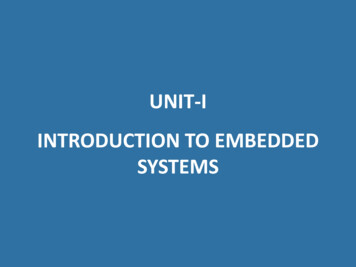
MODEL-BASED DESIGN for EMBEDDED SOFTWARE“Lifecycle” in MBD FrameworkMBD refers to the use of models and modelling environments as the basis of embedded systems development. Amodel represents a dynamic system whose response at any time is a mathematical function based on their inputs,current state, and current time. MBD provides graphical modelling environments consisting of block diagrams andstate machines and is used to analyze, simulate, prototype, specify, and deploy software algorithms within a variety ofembedded systems and applications.Systems for which embedded software can be developed using MBD include: Aircraft avionics systems Commercial vehicle electronics Power plant regulators Digital motor controllers Medical devices Audio signal processorsFigure 1: MBD workflow within V Cycle3
MODEL-BASED DESIGN for EMBEDDED SOFTWAREThe Model-Based Design framework typically includes the following steps: Modeling Simulation Rapid prototyping Embedded deployment In-the-loop testing Integral activitiesModeling:System Modeling activities involve creating a mathematical and behavioral representation of the system underconsideration. Within an MBD framework, it refers to a visual method used to design complex control systems,communication systems and signal processing systems. Such systems represent a dynamic setup whose response atany time is a mathematical function based on their input, current state and current time.In a graphical modeling environment, the use of block diagrams and state machines enable faster design andimplementation. Blocks and lines can be real or virtual. Virtual blocks or lines have no effects on the simulation resultsbut help in constructing or understanding diagrams. Blocks and subsystems can be stored in custom libraries for reuseand abstraction. This enables consistency across subsequent design cycles as well.Models can be classified as either continuous-time systems or discrete-time systems depending on whether themodel contains continuous or discrete dynamics. A continuous-time system is a system where the state of the systemis continuously changing. Continuous system models are used to represent analog signals or real-world effects wheretime continues without interruption. Such continuous time models represent systems under control such as vehicle,turbine, hydraulic actuator or a chemical reactor.A discrete-time system is one in which the state of the system changes at finite intervals of time. An example of adiscrete-time system is an embedded software running on a microcontroller since it relies on clocks or interrupts tobegin executing an algorithm. A typical system model can be hybrid and may contain both continuous-time anddiscrete-time dynamics. Simulation and code generation are integral parts of MBD Framework.Simulation:During simulation, continuous-time systems are solved using numerical integration. There are two types of solvers thatare used within MBD environments. These are: Fixed-step solvers Variable-step solversFixed-step solvers use explicit methods to compute the next continuous state at fixed periodic intervals of time. Avariable-step solver uses explicit or implicit methods to compute the next continuous state at non-periodic intervalsof time. A sample time also needs to be selected. For fixed-step solvers, the sample time is the fixed step time andfor variable-step solvers, the sample time is the maximum allowable sample time. So, the goal during simulation is tochoose a sample time and integration method that will provide an accurate approximation of the continuous system’sbehaviour.4
MODEL-BASED DESIGN for EMBEDDED SOFTWAREVariable step solvers and continuous-time systems do not lend themselves well to deterministic real-time executables,so this combination should be used carefully on those portions of the model that are targeted while design ofembedded system software design and subsequent code generation. The discrete systems, on the other hand, havetheir states explicitly updated and are well-suited for code generation. They execute at an appropriate sample time,or interrupt, and generate outputs. If a system has only one sample time, it is single rate. If the system has multiplesample times, it is multirate. The multirate systems can be executed using either a single tasking form of execution ora multitasking form. In case multitasking execution is used, it often conforms to rate monotonic scheduling within theembedded RTOS environment.Rapid prototyping:Rapid prototyping provides a fast and cost-effective way for control and signal processing engineers to verify designsat early stage and evaluate design trade-offs.Bypass rapid prototyping – Here, code is generated from the controller or algorithm model. The code is thencross-compiled and downloaded to a high-speed, rapid-prototyping computer where it executes in real time. I/Ois managed by memory pod or emulation device that is connected to both the rapid prototyping computer and anexisting embedded controller (e.g. usually an existing ECU or LRU). The controller parameters are tweaked “on-thefly” during test drives or in the lab involving the actual plant (e.g., engine) while allowing for the insertion of new codeto bypass existing ECU code. The design is finalized when performance requirements are met, proving that the newalgorithm is practicable. Please see Figure 2.Controller ModelPlant ModelRapid Prototyping TargetSystem (e.g. Brake Hydraulics, Engine, Turbine)HarnessFigure 2: Bypass rapid prototypingOn-target rapid prototyping – As in the case of bypass rapid prototyping, the code is generated just for the controllerportion of the model. Then the code is cross-compiled and downloaded on to the embedded microprocessor insideECU/LRU used for final deployment. Alternatively, the code can be executed on an embedded platform that is a veryclose approximation of ECU/LRU and configured with a similar memory and I/Os. It often uses a fixed-point integermicro-processor and hence, needs a more detailed, fixed-point model, as opposed to the floating-point processorsand models used for bypass rapid prototyping. The I/Os are managed via standard ECU/LRU devices.The host computer then interfaces directly with the ECU/LRU hardware that is typically mounted on the system undercontrol. The controller parameters are tweaked “on the- fly.” Success is stated when performance requirements are5
MODEL-BASED DESIGN for EMBEDDED SOFTWAREmet, proving that the new algorithm is both possible and practical. See Figure 3.Plant ModelController ModelHarnessEmbedded Target (LRU/ECU)System (e.g. Brake Hydraulics, Engine, Turbine)Figure 3: On-target rapid prototypingEmbedded deployment:After rapid prototyping, a detailed software design activity is performed to convert the controller model to a detailed,executable software specification. The model is created and elaborated to perform properly on embedded systemhardware. Embedded code (often highly optimized) is then generated from the model for the detailed controllermodel and downloaded to the actual embedded microprocessor or ECU as part of the production software build.Often, minimum amount of simulation activity is associated with this step. The key here is to ensure that the final buildon ECU/LRU encompasses fully integrated, automatically generated code with existing legacy code, I/O drivers, andreal-time operating system (RTOS) software.There are two approaches to code-generation embedded deployment. The first approach is to generate code forthe functions and then integrate into the overall hand written application. A second, emerging approach is to use themodel to generate the entire application.IN-THE-LOOP testing:To combine hardware and production code into model-based testing, one can compare dynamic outputs of modelswith data collected through software-in-the-loop and processor-in-the-loop test or with data measured in the test lab,using the data inspector or logging tools.SimulinkPlantModelControllerModelCode GenerationHost-Compiled C with Sfunction wrapper (DLL)Figure 4: Software-in-the-loop (SIL)6
MODEL-BASED DESIGN for EMBEDDED SOFTWARESoftware-in-the-loop (SIL):This testing includes executing the production code for the controller within the modeling environment for non-realtime execution with the plant model and interaction with the user. The code executes on the same host platform thatis being used by the modeling environment. A code wrapper of the generated code provides the interface betweenthe simulation and the generated code as shown in figure 4.Processor-in-the-loop (PIL):This testing is similar to SIL in that it also executes the production code for the controller. However the code executeson the actual embedded processor or an instruction set simulator, so that this verifies the code behaviour on theactual target. Real I/Os via CAN or serial devices are used to pass data between the production code executing onthe processor and a plant model executing in the modelling environment. As with SIL, PIL testing is a non-real-timeexecution scenario as shown in figure 5.SimulinkPlant ModelControllerModelCode GenerationEmbedded TargetFigure 5: Processor-in-the-loop (PIL)Hardware-in-the-loop (HIL):In this testing, the code is also generated for the plant model. It runs on a highly deterministic, real-time computer.Signal conditioning and power electronics are needed to properly stimulate the ECU/LRU inputs (sensors) and receivethe ECU/LRU outputs (actuator commands). Whereas, rapid prototyping is often a development or design activity, HILserves as a final lab test phase before final system integration and field tests commence. See Figure 6.SimulinkControllerModelPlantModelCode GenerationCode GenerationEngine Control Unit(ECU)HarnessI/OInterfacesReal-timePCFigure 6: Hardware-in-the-loop (HIL)7
MODEL-BASED DESIGN for EMBEDDED SOFTWAREIntegral activities:Most of the MBD environments automate the generation of documentation from models. In this case, thedocumentation is in template form allowing users to specify the content of each documentation section. Therequirements traceability is accomplished using interfaces between blocks in the model and existing requirementmanagement sources. The code generated from the model can also be traced back to the block, letting auditors tracehigh-level requirements all the way back to the code. As with requirements management, the source control for amodel may be accomplished outside the modeling environment using existing source control products. Interfaces areprovided that let developers check in and check out models as well as document the changes.8
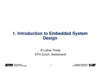
MODEL-BASED DESIGN for EMBEDDED SOFTWAREMBD for migration and optimisation of DSP libraries – Case Study 1:In this project, eInfochips team converted highly complex DSP algorithms library from embedded C into optimizedSimulink Models. The C DSP libraries are used for audio and video compression. The major benefits of the code tomodel migration process are: Model is easier to maintain and document compared to legacy code and algorithms Features additions and enhancements – shorter time cycles with MBD Model-based autocode generation – easier migration during hardware upgrades Automatic test case generation from Models – reduce V&V iterations Effective as knowledge capture mechanismeInfochips team has implemented the process below in Figure 7 for the MBD migration:Figure 7: C Hand code to MBD MigrationPerformance evaluation:Along with benefits of the MBD framework listed above, it is often necessary to compare the real-time performance ofthe auto-code generated from Simulink models with original hand-written C code. Table no. 1 shows results derivedfor one of the DSP algorithm: FIR filter with 87 taps. From inspection of the results, it is observed that the auto-codegenerated from a model is efficient and needs a smaller amount of CPU time to execute than the equivalent handcode.Table 1: Average Time taken by FIR function for threedifferent inputs9
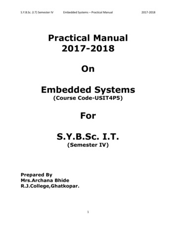
MODEL-BASED DESIGN for EMBEDDED SOFTWAREMBD for real-time diagnostics system – Case Study 2:In this project, eInfochips team designed real-time algorithms for on-board fault diagnostics using an MBD framework.The setup consists of a simulation of a 5 MW wind turbine and its speed and yaw control system. This setup allowsinsertion of system and sensor faults by means of changes to parameters and additional signal injections at suitablepoints. The diagnostics algorithms must detect the faults in real-time so that corrective actions can be initiated by thecontrol system or a supervisory logic.Such algorithms operate on sensor data as well as on prior design data. In case of high value and/or criticalengineering systems (e.g. wind turbine, jet-engine) the diagnostics shall run in real time to prevent catastrophicsituations or costly repairs before a fault propagates within the system. In this context, eInfochips has created asolution for real-time monitoring applicable to systems such as complex electro-mechanical systems and rotatingmachinery. The fault detection algorithms library includes Kalman filters (EKFs), fault tree tables (FTTs), fast Fouriertransform (FFT) frequency analyzer and others. This solution is capable of running on various prototyping anddeployable embedded platforms based on TI AM57x, Freescale MPC56xx, ARM CORTEX M4 and Arduino. Figure 8.shows the setup and some of the results from real-time HIL rig.Figure 8: MBD of real-time diagnostics solution10
MODEL-BASED DESIGN for EMBEDDED SOFTWAREReferences:1. A. V. Oppenheim and R. W. Schafer, “Discrete-Time Signal Processing”, Prentice Hall; US ed edition (2 January 1975)2. Vinay K. Ingle, John G. Proakis, Northeastern University, ‘’Digital Signal Processing Using MATLAB’’, Third Edition,Global Engineering: Christopher M. Shortt, 2010.3. William Alberto, Quinchanegua Sánchez, ‘’Signal Processing Implementations Using Simulink’’, www.ece.uprm.edu/crc/crc2003/papers/Alberto QunchaOr.pdf4. The Mathworks, Inc, https://in.mathworks.com/solutions/dsp/ABOUT AUTHORSDr Mangesh Kale is Senior Solution Architect and Key Accounts Manager at eInfochips. He has industryexperience of more than 18 years in engineering, technology design and solutions for safety critical controlsystems hardware and software. Mangesh leads the aerospace practice group at eInfochips with responsibilityof new technology initiatives and research & development initiatives. Mangesh has a PhD from The University ofSouthampton, UK in flight control systems, Masters of Engineering from Indian Institute of Science Bangalore andBachelors of Engineering from University of Pune, India.Anupama Shendage is an engineer at einfochips. Her area of interest includes Digital signal processing,Embedded Systems, image processing and automotive advancements and applications. She has done Bachelorsdegree in Electronics and Telecommunication engineering from Department of Technology Kolhapur, India.11
MODEL-BASED DESIGN for EMBEDDED SOFTWAREAbout eInfochipseInfochips is a global technology firm specializing in product engineering and software R&D services, we enabledigital transformation for companies in Aerospace, consumer devices, Automotive devices, industrial automation,media and broadcast, medical devices and healthcare, We have contributed to 500 products and over 10mdeployments across the world. The company has a proud 20-year history, focused exclusively on R&D services forproduct companies. We have grown organically over that time to more than 1500 engineering, serving clients from ourUS headquarters in Sunnyvale, California and from sales and design centers across the US and India. The company hassales presence in across the world such as USA, UK, Japan, Canada, and India.
MODEL-BASED DESIGN for EMBEDDED SOFTWARE Need for Model Based Development Model-based design (MBD) is a framework used in virtual prototyping of embedded software. MBD has evolved to overcome various difficulties and complexities that typically arise during the design lifecycle of embedded s