Transcription
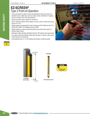
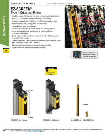
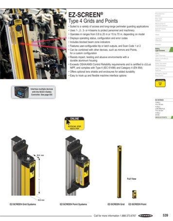
EZ-SCREEN PhotoelectricsSensorsType 4 Grids and PointsFiber OpticSensors Suited to a variety of access and long-range perimeter guarding applications Uses 1-, 2-, 3- or 4-beams to protect personnel and machinery Operates in ranges from 0.8 to 20 m or 15 to 70 m, depending on model Displays operating status, configuration and error codes Includes blocked beam zone indicators Features user-configurable trip or latch outputs, and Scan Code 1 or 2 Can be combined with other devices, such as mirrors and Points,for a custom configuration Resists impact, twisting and abusive environments with adurable aluminum housing Exceeds OSHA/ANSI Control Reliability requirements and is certified to cULusNIPF, and complies with Type 4 (IEC 61496) and Category 4 (EN 954) Offers optional lens shields and enclosures for added durability Easy to hook up and flexible machine interface optionsMeasurement &Inspection SensorsSpecial PurposeSensorsVisionLighting &IndicatorsWirelessSafetyLight ScreensSafetyLaser ScannersSafety Controllers &ModulesSafety Two-HandControl ModulesSafety InterlockSwitchesEmergency Stop &Stop ControlACCESSORIESpage544Interface multiple deviceswith the SC22-3 SafetyController. See page 555EZ-SCREENTYPE 414 or 30 mmTYPE 4LOW PROFILE14 or 25 mmTYPE 230 mmGRIDS & POINTSonlineAUTOCAD, STEP,IGES & PDF55.0 mmFull ViewL52.0 mmEZ-SCREEN Grid SystemsEZ-SCREEN Point SystemsEZ-SCREEN GridEZ-SCREEN PointCall for more information 1.888.373.6767539
EZ-SCREEN (TYPE 4)GRIDS & POINTSEZ-SCREEN (TYPE 2)EZ-SCREEN Grid Systems Model Key, 24V dcModel StyleNumber ofBeamsMACHINE SAFETYSGESG Safety Grid (Receiver &Short Range Emitters)SGXL Safety Grid (Long RangeEmitters & Pairs)Beam SpacingConnection(mm)Emitter/ReceiverPair †3E EmitterR ReceiverP Pair †533300400500533584ACCESSORIESorQ8E 8-pin QD2 500 or 5843 400 or 5334 300BeamSpacing†Q8EProtectedHeight (mm) Q88E Emitter with 8-pin QDReceiver with 8-pin QD9008005001066584A pair includes an emitter and receiver (example, SGP3-533Q88E)Contact Banner Engineering Corp. for additional information and/or verification of valid kit model numbers.page544A model with a QD requires a mating cordset (see page 544). For emitters and receivers with a wiring terminal chamber, remove the Q8E or Q88E from the model number (example, SGE4-300). For an emitter with a 5-pin Mini QD and TEST function,replace Q8E with Q5 on emitter model numbers (example, SGE4-300Q5) and Q88E with Q85 on pair model numbers (example, SGP4-300Q85).For emitters with a 3-pin Mini QD, replace Q8E with Q3 (example, SGE4-300Q3); and for receivers with an 8-pin Mini QD, replace Q8E with Q8 on model numbers (example, SGR4-300Q8);or for a pair replace Q88E with Q83 (example, SGP4-300Q83).EZ-SCREEN Point Systems Model Key, 24V dcModel StyleSPSP Safety Point (Receiver &Short Range Emitters)SPXL Safety Point (Long RangeEmitters & Pairs)Number ofBeamsEE EmitterR ReceiverP Pair †11 Point ModelsConnectionEmitter/ReceiverPair †Q8EorQ8E 8-pin QDQ88E Emitter with 8-pin QDReceiver with 8-pin QD†A pair includes an emitter and receiver (example, SPP1Q88E)Contact Banner Engineering Corp. for additional information and/or verification of valid kit model numbers.A model with a QD requires a mating cordset (see page 544). For emitters and receivers with a wiring terminal chamber, remove the Q8E or Q88E from the model number (example, SPE1). For an emitter with a 5-pin Mini QD and TEST function,replace Q8E with Q5 on emitter model numbers (example, SPE1Q5) and Q88E with Q85 on pair model numbers (example, SP1Q85).For emitters with a 3-pin Mini QD, replace Q8E with Q3 (example, SPE1Q3); and for receivers with an 8-pin Mini QD, replace Q8E with Q8 on model numbers (example, SPR1Q8);or for a pair replace Q88E with Q83 (example, SPP1Q83).540More information online at bannerengineering.com
EZ-SCREEN Grids & Point KitsPhotoelectricsSensorsYou can purchase a kit that contains an emitter and receiver of equal length and beam spacing; brackets; and optionalinterfacing solution and quick-disconnect cordsets. Detailed information about individual kit components is as follows. Emitter and ReceiversPage 540 Interfacing Options545 Cordsets544 Brackets544Fiber OpticSensorsMeasurement &Inspection SensorsSpecial PurposeSensorsVisionLighting &IndicatorsWirelessSafetyLight ScreensSafetyLaser ScannersTo Order:1. Choose model range, number of beams and beam spacing.2. Choose the connection: Integral M12/Euro-Style QD or intergalMini-Style QD3. Choose an optional interfacing solution, such as an IM-T-9A or -11interfacing model.4. Choose one cordset for each sensor or two cordsets for a pair.Safety Controllers &ModulesM12/Euro QD models (example, SGK4-300Q88E) requiremating 8-pin M12/Euro QD cordsets, such as:- QDE cordset with flying leads- DEE2R double-ended cordset- CSB series splitter cordsetMini QD models (example, SGK4-300Q83) requiremating cordsets, such as:- QDS cordset with flying leadsSee www.bannerengineering.com for complete information and a currentlisting of accessories and options for kitting components. Call factory withquestions regarding accessories.Safety Two-HandControl ModulesSafety InterlockSwitchesEmergency Stop &Stop ControlACCESSORIESpage544EZ-SCREENEZ-SCREEN Grid & Point Systems Kit Model Key Model StyleKitNumber ofBeamsSGK4SG Safety GridSGXL Safety GridLong RangeSP Safety PointSPXL Safety PointLong RangeK KitBeam Spacing Interfacing(mm)ConnectionOptions300Q88EBeam spacing options2 500 or 584 (grid)3 400 or 533 (grid)4 300 (grid)1 Point modelsBeamSpacing300400500ProtectedHeight (mm) 900 800 500BeamSpacing533584BlankProtectedHeight (mm) 1066 5841QD CordsetLength OptionsTYPE 414 or 30 mmTYPE 4LOW PROFILE14 or 25 mmTYPE 230 mmGRIDS & POINTSRE25RE15 4.6 m, 2 eachRE25 7.6 m, 2 eachR15E25 4.6 m (Receiver) & 7.6 m (Emitter)R25E15 7.6 m (Receiver) & 4.6 m (Emitter)DD1 0.3 DEE2R-81D, 2 eachC1D15 CSB-M1281M1281 (Receiver)DEE2R-815D (8-pin Emitter)C8D25 CSB-M1288M1281 (Receiver)DEE2R-825D (8-pin Emitter)CU25D25 CSB-UNT825M1281 (Receiver)DEE2R-825D (8-pin Emitter) Point modelsQ88E E mitter and receiver withintegral 8-pin M12/Euro QD1 IM-T-9A Interface Module, 1 each (3 NO)2 IM-T-11A Interface Module, 1 each (2 NO/1 NC)3 11-BG00-31-D-024 Contactors (10A), 2 each4 BF1801L-024 Contactors (18A), 2 each5 EZAC-R9-QE8 AC Interface Box (3 NO), 1 each6 EZAC-R11-QE8 AC Interface Box (2 NO/1 NC), 1 eachCall for more information 1.888.373.6767541
EZ-SCREEN (TYPE 4)EZ-SCREEN (TYPE 2)GRIDS & POINTSMACHINE SAFETYEZ-SCREEN Grid & Point SpecificationsSupply Voltage (V in)24V dc 15%, 10% max. rippleSupply CurrentEmitter: 150 mA max.Receiver: 500 mA max., exclusive of OSSD1 and OSSD2 loads (up to an additional 0.5A each)Short Circuit ProtectionAll inputs and outputs are protected from short circuits to 24V dc or dc common (except Emitter AUX power connections)Response Time24 milliseconds or less from interruption of light grid beam to safety outputs going to OFF-stateEDM Input 24V dc signals from external device contacts can be monitored (single-channel, dual-channel or no monitoring) via EDM1 andEDM2 terminals in the receiver. Monitored devices must respond within 200 milliseconds of an output change.Reset InputThe Reset input must be high (10 to 30V dc at 30 mA) for 0.25 to 2 seconds and then low (less than 3V dc) to reset the receiver.Remote Test Input(optional- available only oncertain models)Test mode is activated either by applying a low signal (less than 3V dc) to emitter TEST1 terminal for a minimum of 50 milliseconds,or by opening a switch connected between TEST1 and TEST2 terminals for a minimum of 50 milliseconds. Beam scanning stops tosimulate a blocked condition. A high signal (10 to 30V dc, 35 mA inrush, 10 mA max.) at TEST1 terminal deactivates Test mode andallows the emitter to operate normally. TEST1 and TEST2 are factory jumpered on models with wiring chamber.Safety OutputsTwo diverse-redundant solid-state 24V dc, 0.5 A max. sourcing OSSD (Output Signal Switching Device) safety outputs.(Use optional interface modules for ac or larger dc loads.) Capable of the Banner “Safety Handshake.”ON-State voltage: Vin-1.5V dcOFF-State voltage: 1.2V dc max.Max. load capacitance: 0.1 µFMax. load resistance: 1000 ΩOSSD test pulse width: 250 microsecondsOSSD test pulse period: 6 millisecondsControls and AdjustmentsEmitter: Scan code selection: 2-position switch (code 1 or 2). Factory default position is 1.Receiver: Scan code selection: 2-position switch (code 1 or 2). Factory default position is 1.Trip/latch output selection: redundant switches. Factory default position is L (latch)EDM/MPCE monitor selection: redundant switches select between 1- or 2-channel monitoring.Factory default position is 2.542Emitter/Receiver Operating RangeLong-range models: 15 m to 70 mShort-range models: 0.8 m to 20 mRange decreases with use of mirrors and/or lens shields.Beam SpacingModel SG.4-300: 300 mmModel SG.2-500: 500 mmModel SG.2-584: 584.2 mmBeam Diameter25 mmAmbient Light Immunity 10,000 lux at 5 angle of incidenceStrobe Light ImmunityTotally immune to one Federal Signal Corp. “Fireball” model FB2PST strobeEmitter ElementsInfrared LEDs, 880 nm at peak emissionEffective Aperture Angle (EAA)Meets Type 4 requirements per IEC 61496-2Short-range models: 2.5 @ 3 mModel SG.3-400: 400 mmModel SG.3-533: 533.4 mmLong-range models: 2.5 @ 15 mEnclosureMaterials: Extruded aluminum housings with yellow polyester powder finish and well-sealed, rugged molded PBT end caps,acrylic lens coverRating: NEMA 4, 13; IP65Operating ConditionsTemperature: 0 to 50 CShock and VibrationEZ-SCREEN systems have passed vibration and shock tests according to IEC 61496-1/-2. This includes vibration (10 cycles) of10-55 Hz at 0.35 mm single amplitude (0.70 mm peak-to-peak) and shock of 10 g for 16 milliseconds (6,000 cycles).More information online at bannerengineering.comRelative humidity: 95% (non-condensing)Moreon nextpage
EZ-SCREEN Grid & Point SpecificationsStatus IndicatorsPhotoelectricsSensors(cont’d)7-Segment Diagnostic Indicators, Both Emitter and ReceiverDash (–) System is OKError Codes See product manuals (p/n 68410 or 68413) for code definitions and recommended actionScan code setting Appears during power-up or after scan code is changed.(C1 or C2) (Temporary indication; normal display resumes within a few seconds.)Emitter: One bicolor (red/green) Status indicatorGreen steady RUN modeGreen single flashing TEST modeRed single flashing LockoutOFF No power to sensorReceiver: Two System Status indicators, plus one bi-color (red/green) Beam Status indicator for each beamYellow Reset IndicatorON steady RUN modeDouble flashing Waiting for manual reset after power-upSingle flashing Waiting for manual latch resetOFF No power to sensor or system is not ready for operationBicolor (Red/Green) Status IndicatorGreen steady Outputs ONRed steady RUN mode, outputs OFFRed single flashing LockoutOFF No power to sensor or system is not ready for operationBicolor (Red/Green) Beam Status IndicatorsGreen steady Clear beam, strong signalGreen flickering Clear beam, weak signalRed steady Beam blockedOFF No power to sensor or no scanningMounting HardwareEmitter and receiver each are supplied with a pair of swivel end mounting brackets. Mounting brackets are 8-gauge cold-rolledsteel, black zinc finish.Cables and ConnectionsCables are user-supplied. Wiring terminals accommodate one 22 to 16 ga. wire or two wires up to 18 ga.; Pg 13.5 wiringchamber access port capacity varies, depending on cable gland or strain relief fitting used. Supplied cable gland is for a cablediameter of 6 to 12 mm.Design StandardsDesigned to comply with Type 4 per IEC 61496-1, -2; Type 4 per UL 61496-1/-2; Category 4 per ISO 13849-1 (EN 954-1)CertificationsWiring DiagramsFiber OpticSensorsMeasurement &Inspection SensorsSpecial PurposeSensorsVisionLighting &IndicatorsWirelessSafetyLight ScreensSafetyLaser ScannersSafety Controllers &ModulesSafety Two-HandControl ModulesSafety InterlockSwitchesEmergency Stop &Stop ControlEZ-SCREENTYPE 414 or 30 mmTYPE 4LOW PROFILE14 or 25 mmTYPE 230 mmGRIDS & POINTSImportant Notice:European Community Machinery Directive 2006/42/ECEZ-SCREEN grids and points comply with Machinery Directive 98/37/EC, but not with MachineryDirective 2006/42/EC. Therefore, the EZ-SCREEN grids and points can only be installed as areplacement component within the European Union (EU). For more information,please see www.bannerengineering.com/144763 or call 1-888-373-6767.WD011, WD012, WD013, WD014, WD015, WD016, WD017, WD018, WD019 (p . 825-830)Call for more information 1.888.373.6767543
MACHINE SAFETYCordsetsEuro QDEuro QD SplitterSee page 732See page 735Length8-Pin4.57 mQDE-815DLengthEuro QD–Double-EndedSee page 7338-Pin0mCSB-M1280M1280Length8-Pin0.31 mDEE2R-81D7.62 mQDE-825D0.30 mCSB-M1281M12810.91 mDEE2R-83D15.3 mQDE-850D2.50 mCSB-M1288M12812.44 mDEE2R-88D22.9 mQDE-875D4.60 mCSB-M12815M12814.57 mDEE2R-815D30.5 mQDE-8100D7.60 mCSB-M12825M12817.62 mDEE2R-825D7.60 mCSB-UNT825M128115.2 mDEE2R-850D22.9 mDEE2R-875D30.5 mDEE2R-8100DAdditional cordset information available.See page 721.* For connection to safety BUS gateway/node, a “smart” self-monitoredsafety module, safety controller or safety PLC see page 733.BracketsGrids & Points–Type 4pg. 666pg. 668EZA-MBK-1*pg. 669EZA-MBK-3Points–Type 4pg. 667EZA-MBK-9pg. 668EZA-MBK-2**pg. 668EZA-MBK-4EZA-MBK-5Additional bracket information available.See page 656.* Standard brackets included with emitter/receiver.** One EZA-MBK-2 adapter bracket kit required per sensor when mounting to MSA series stands.NOTE: See page 545 for interfacing solutions.Replacement PartsModelDescriptionEZA-AP-1Access port plug with o-ringEZA-CP-13Pg13.5 plug with o-ringEZA-ECE-1Emitter wiring chamber end cap (with gasket, captive screws, 3 plugs with o-rings, terminal block)EZA-ECR-1Receiver wiring chamber end cap (with gasket, captive screws, 3 plugs with o-rings, terminal block)EZA-SW-1Spanner wrench for Grid and PointEZA-TBE-1Emitter terminal blockEZA-TBR-1Receiver terminal blockMGA-K-1Replacement key for switch MGA-KS0-1MGA-KS0-1Panel-mount keyed normally open reset switchSTP-3Specified test piece, 45 mm dia.NOTE: See installation manual p/n 112852 for complete list of replacement parts and accessories.544STANDSMIRRORSPAGE 766PAGE 770LENS SHIELDSPAGE 776More information online at bannerengineering.comINTERFACEENCLOSURESPAGE 545PAGE 772
542 MACHINE SAFETY More information online at bannerengineering.com EZ-SCREEN (TYPE 4) EZ-SCREEN (TYPE 2) GRIDS & POINTS EZ-SCREEN Grid & Point Specifications Supply Voltage (V in) 24V dc 15%, 10% max. ripple Supply Current Emitter: 150 mA max. Receiver: 500 mA max., exclusive of OSSD1 and OS