Transcription
http://dx.doi.org/10.1595/205651315X688686Johnson Matthey Technol. Rev., 2015, 59, (3), 243–256JOHNSON MATTHEYTECHNOLOGY REVIEWwww.technology.matthey.comIntroduction to the Additive Manufacturing PowderMetallurgy Supply ChainExploring the production and supply of metal powders for AM processesBy Jason Dawes*, Robert Bowerman andRoss TrepletonComponent Technologies, Manufacturing TechnologyCentre, Pilot Way, Ansty Business Park, Coventry,CV7 9JU, UK*Email: jason.dawes@the-mtc.orgThe supply chain for metal powders used in additivemanufacturing (AM) is currently experiencingexponential growth and with this growth comenew powder suppliers, new powder manufacturingmethods and increased competition. The highnumber of potential supply chain options providesAM service providers with a significant challengewhen making decisions on powder procurement.This paper provides an overview of the metal powdersupply chain for the AM market and aims to give AMservice providers the information necessary to makeinformed decisions when procuring metal powders.The procurement options are categorised into threemain groups, namely: procuring powders from AMequipment suppliers, procuring powders from thirdparty suppliers and procuring powders directly frompowder atomisers. Each of the procurement optionshas its own unique advantages and disadvantages.The relative importance of these will depend on whatthe AM equipment is being used for, for exampleresearch, rapid prototyping or productionisation.The future of the metal AM powder market is alsodiscussed.2431. IntroductionA component fabricated using powder bed may consistof many thousands of finely spread powder layers. Theuniformity of these layers can affect the properties of thefinal component. The way in which a powder ‘spreads’during AM depends on the properties of the powderused. As will be discussed in this paper, even whenchemically equivalent, the properties of metal powdersvary widely depending on both the atomisation methodused and the manufacturing process conditions. Toobtain a greater degree of control over AM processesservice providers must be able to control the quality ofthe raw powder feedstock.The overall AM market has seen exponential growthover the last five years and during this time the saleof powder bed metal AM equipment, services andproducts has also followed an exponential trend (1)due to increased adoption from the aerospace, oiland gas, marine, automobile and medical sectors. Asthe benefits of using AM to manufacture functionalmetallic components start to outweigh the blockers,more component manufacturers are looking towardsmetal powder bed technologies to allow them to realisetheir next generation of innovatively and functionallydesigned products.Research has shown that metal powder costs will bethe biggest continuous expense through the life of anAM machine (1). The quality and consistency of the AMcomponents depends, in part, on the characteristicsof the starting powder feedstock. Hence, controllingand understanding the quality of the powder both in 2015 Johnson Matthey
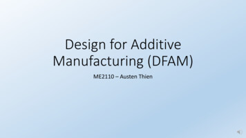
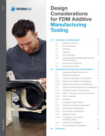
Johnson Matthey Technol. Rev., 2015, 59, (3)http://dx.doi.org/10.1595/205651315X688686Over the last 20 year period the AM market has grownrapidly from an industry worth US 100 million in 1993to around US 3000 million in 2013, see Figure 1.YearFig. 1. AM market growth 1991–2013 3002002250040071.00ServicesProducts2001Value, US t value, US million3500All AM MaterialsMetallic AM materials only500327.10600528.802. Overview of the Powder Bed AM MarketCurrent predictions forecast that this rapid growthwill continue and that there will be a five-fold marketvalue increase by 2021 (1). This growth trend in AMtechnology is also reflected in global raw materials(powder) sales. Powder sales in the AM sector over thepast decade are shown in Figure 2. After a decline insales in 2009, due to market reaction at the beginningof the fiscal crisis, both the AM sector value and AMmaterial sales have seen rapid growth since 2010.Specific to metal powder AM, the sale of powder formetal processes is also shown in Figure 2. It can beseen that metal sales have followed the market trendsince 2010, with sales more than doubling in a threeyear period. However, the value of the metal powderAM market is a relatively small proportion of the wholemarket. This highlights the opportunity for growth forpowder suppliers offering products into the metals AMmarket.Based on data from 2013 there are 855 powdermanufacturers worldwide (425 located in NorthAmerica, 205 in Europe and 225 in the Asia-Pacificregion) capable of producing an estimated 1.12million metric tonnes, to a value of approximatelyUS 6.9 billion (2). The top six powder manufacturershave a combined market share of 44% and generallyserve the press and sinter market. The remainingmarket share is made up of small businesses, likelyproducing powder for a specific purpose or application.When the metal powder market is evaluated, onlyUS 32.6 million was sold for AM usage (0.0047%).This shows that despite the enormous anticipation ofthe impact of AM, traditional powder processes such417.00its as-supplied and reused condition is essential inorder to achieve the desired mechanical properties ofthe laser melted components. Given the significanceof the metal powder feedstock it is important that AMusers make informed decisions when procuring theraw metal powder. The current state of the AM metalpowder supply chain is that there are multiple possiblemethods for the manufacture of metal powders andmany times as many potential suppliers. Furthermorenot all metal powders are equal in terms of theirfundamental properties even when manufactured viathe same technique (when procured from differentvendors). This presents quite a challenge to beginnersin AM technology when deciding on a powder supplier.However, some AM equipment suppliers, such as EOS,sell ‘validated powder’. ‘Validated powder’ is a powderwhich has been identified as suitable for use in AM.Whilst validated powder can de-risk procuring powdersfor AM it does limit users to a single source supplierand inhibits the development of in-house expertise.Given the complexity of the AM metal powder supplychain this review article aims to resolve some of theconfusion involved and address some of the frequentlyasked questions by users. Additionally, the article willhighlight key issues that the market needs to address,and make potential users aware of some of the keyfactors to consider when selecting the most appropriatepowder supplier.YearFig. 2. History of materials sales for AM systems worldwide:(–) all AM materials, (–) metallic AM materials only (metallicpowder sale data not available prior to 2009) (1) 2015 Johnson Matthey
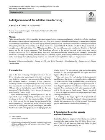
http://dx.doi.org/10.1595/205651315X688686as press and sinter and metal injection moulding(MIM) still dominate the marketplace. However, as AMprocesses become more established as componentmanufacturing routes, rather than rapid prototypingtechnologies, the potential for growth in the metal AMpowder supply is considerable.3. Selection of AM Powder3.1 The Importance of PowderThe AM process uses powder as its raw materialfeedstock, as such the consistency of the powdersused to build AM components will have a criticalinfluence on the final component properties. During thebuild sequence of an AM component, the raw powderfeedstock is stored in a hopper, the design of the hopperand the method by which powder is introduced intothe build chamber depends entirely on the equipmentmanufacturer. A discrete amount of powder from thehopper is spread (either using a rake or roller system)across the build chamber to form a thin (no more thanone to two particle diameters) continuous layer ofpowder. After spreading it is critical that the layer ishomogenous over the entire area of the build chamber,any degree of inhomogeneity may result in porosity (inthe absence of powder) or incomplete through-thicknessmelting (too much powder pooled up in one area). Thespread layer is selectively fused using either a lasersource or an electron beam based on an input slicedthree-dimensional (3D) computer aided design (CAD)model. Following selective sintering another layer ofpowder is spread over the first. This iterative processof powder spreading followed by selective melting iscontinued until the build is complete. The total numberof powder layers spread will of course depend on thesize of component being built but the number could bein the region of 7000 layers. Furthermore it is commonto build multiple components during one build event.The layer spreading, hopper dosing and bulk packingperformance of the AM powder will depend entirelyon the properties of the powder being used. Furthercomplicating the use of AM powder is that the volumeof the actual component built can be significantly lessthan the total volume of powder that has been spread.As a consequence there is a large amount of unusedpowder left over in the build chamber, given the highcost of metal powders it is essential that the unusedpowder is effectively recovered and reused in futurebuilds. However, the effect of continued recycling of245Johnson Matthey Technol. Rev., 2015, 59, (3)the unused powder on the actual powder propertiesand hence subsequent component properties has notbeen the subject of intensive scientific study. In the fewscientific journals published in the field of metal powderrecycling in AM, it has been observed that recyclingpowders in powder bed AM processes results in anincrease in powder particle size distribution (PSD) (2,3). The thermal effects that result from the process,such as chamber temperature and the radiation energyin selective laser melting (SLM) of metal powders,may cause physical as well as chemical changes tothe recycled powder. Furthermore contamination,either through impurities, foreign bodies or interstitialelements may be introduced to the powder as a resultof handling during pre-processing or post-processingstages.The first step in understanding powder requirementsfor AM processes is to assess the types of metallicpowder that are available. The following sectionsprovide an overview of the methods of metal powderproduction routes.3.2 Routes of Powder ProductionThe production of AM metal powder generally consistsof three major stages as outlined in the flow diagramshown in Figure 3. Briefly, the first stage involves themining and extracting of ore to form a pure or alloyedmetal product (ingot, billet and wire) appropriatefor powder production; the second stage is powderproduction and the final stage is classification andvalidation.The supply chain of taking ore and extracting a metalis well established and supplies a vast range of puremetals and specific alloys to global markets. Once aningot of the metal or alloy has been formed a numberof additional processing steps may be required tomake the feedstock suitable for the chosen atomisationprocess. For example, plasma atomisation requires thefeedstock material to be either in wire form or powderform, thus adding additional rolling and drawing work ora first step powder production route.Once the first processing form has been obtainedthere are a number of methods available to producemetal powders including, but not limited to: solid-statereduction, electrolysis, various chemical processes,atomisation and milling. Historically, for reasons thatwill be discussed, atomisation has been identified asthe best way to form metal powders for AM due to thegeometrical properties of the powder it yields. 2015 Johnson Matthey
Johnson Matthey Technol. Rev., 2015, 59, (3)http://dx.doi.org/10.1595/205651315X688686Stage 1OreHydrogenation anddehydrogenationExtractionFormingForming(billet, wire)IngotStage 2Plasma, PREP, REPor EIGA atomisationAtomisationWater atomisationGas or rocessingStage 3ValidationFig. 3. From ore to validated AM powder – powder production steps flow chartNone of the powder production routes actuallyproduce a 100% powder yield in the required sizefractions. Some post processing is therefore necessary.As a minimum, the as-produced metal powder must beclassified into a well-defined particle size distributionsuitable for the required process: typically 15–45 µm forSLM and 45–106 µm for electron beam melting (EBM).3.2.1 Water AtomisationAll atomisation processes begin with melting thefeedstock alloy. The melting process has a number ofvariations, but generally when atomising using water,the feedstock is first melted in a furnace before beingtransferred to a tundish (a crucible that regulates theflow rate of the melt into the atomiser). The liquid alloyenters the atomisation chamber from above; hereit is free to fall through the chamber. Water jets aresymmetrically positioned around the stream of liquidmetal, atomising and solidifying the particles. The final246powder exits at the bottom of the chamber, where it iscollected. Additional processing steps are then requiredto dry the powder. Metal powder produced in thisway is typically highly irregular in morphology whichreduces both packing properties and flow properties.Water atomisation is the main method of producing ironand steel powders and typically feeds into the pressand-sintered industries rather than the specialised AMindustry.3.2.2 Gas AtomisationThe gas atomisation process mimics water atomisation,with the differentiator being the use of gas insteadof water during processing. Air can be used as theatomising media, but it’s more likely that an inert gas(nitrogen or argon) will be used to reduce the risk ofoxidation and contamination of the metal. The processof melting the metal ingots can be the same as describedfor water atomisation, however for powders produced 2015 Johnson Matthey
Johnson Matthey Technol. Rev., 2015, 59, (3)http://dx.doi.org/10.1595/205651315X688686for high end applications such as aerospace, the needto control interstitial elements has led to increaseduse of vacuum induction melting (VIM) furnaces. AVIM furnace is typically installed directly above theatomisation chamber such that the molten stream ofliquid metal enters the atomisation chamber directlyfrom the furnace rather than through a tundish, similarto the set-up shown in Figure 4. The stream of liquidmetal is atomised by high pressure jets of gas. Due tothe lower heat capacity of the gas (compared to water)the metal droplets have an increased solidification timewhich results in comparatively more spherical powderparticles (i.e. droplet spheroidisation time is shorterthan the solidification time). Whilst it is not possibleto have complete control over the particle size of asatomised powder, the distribution can be influenced byvarying the ratio of the gas to melt flow rate. Researchin the field of gas atomisation has shown that even finerparticle size distributions can be achieved through theuse of hot gas atomisation (4).Although interstitial elements can be well controlledin gas atomised powders, there are still potentialcontamination risks. Contamination most pertinent tonon-static critical components, such as aero-engineparts, include refractory materials which can originatefrom the ceramic crucibles and atomising nozzlesused. One solution to this is to use electrode inductionmelting gas atomisation (EIGA). EIGA is a variation ofgas atomisation where the metal is fed into the atomiserin the form of a rod that is melted by an induction coilMeltGas sourceand pumpFig. 5. Schematic of the EIGA process for production of AMpowders (Courtesy of LPW Technology, UK)3.2.3 Plasma AtomisationPlasma atomisation is a method of producing highlyspherical particles. The feedstock used in the processcan either be in wire form such as the method used byAP&C Advanced Powders and Coatings Inc, Canada,or in powder form such as the method used by TeknaPlasma Systems Inc, Canada. The spool of wire orpowder feedstock is fed into the atomisation chamber,where it is simultaneously melted and atomised by coaxial plasma torches and gas jets, such as that shownin Figure 6.Plasma rotating electrode process (PREP) is avariation of plasma atomisation whereby a bar ofrotating feedstock is used instead of a wire feed. As therotating bar enters the atomisation chamber plasmatorches melt the end of the bar, ejecting material fromits surface. The melt solidifies before hitting the walls ofthe chamber.3.2.4 Hydride-Dehydride ProcessFine powderNozzleCollectionchamberFig. 4. Schematic of the gas atomisation process forproduction of AM powders (Courtesy of LPW Technology,UK)247just before entering the atomisation chamber, as shownin Figure 5. This application is used when processingreactive alloys, such as Ti-6Al-4V, minimising the risk ofcontamination from exposure of the molten titanium tothe crucible and the atmosphere (5).The hydride-dehydride (HDH) method (6) of powderproduction differs from the atomisation processesdescribed above due to the fact that it does not involvemelting of the metal feedstock. Instead, it involvescrushing, milling and screening to resize larger lumpsof metal feedstock into finer powder particles. TheHDH process relies on the brittle nature of certainmetals, such as titanium, when exposed to hydrogen.In the case of titanium, titanium hydrides are formed 2015 Johnson Matthey
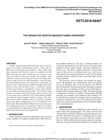
Johnson Matthey Technol. Rev., 2015, 59, (3)http://dx.doi.org/10.1595/205651315X6886863.2.6 Summary of Powder Production RoutesTitaniumspoolPlasmatorchesEach of these processes yields powder with varyingcharacteristics, a summary of which can be seenin Table I. A series of micrographs highlighting thevarious particle morphologies obtained from eachmanufacturing route is shown in Figure 7.3.3 Powder Key Process VariablesVacuumpumpCollectionchamberFig. 6. Schematic of the plasma atomisation process forproduction of AM powders (Courtesy of LPW Technology,UK)in a hydride unit by introducing hydrogen and heat.The brittle lumps can then be crushed and screenedinto the required particle size distribution (PSD). Thepowder is then returned to the hydride unit to removethe excess hydrogen from the metal powder particles.Powder particles produced using HDH are typicallyhighly irregular. HDH powders are typically used eitherin their as-made condition or used as the powderfeedstock for plasma atomisation.3.2.5 TiROTM ProcessThe TiROTM process (7, 8) is a relatively newmethod for the production of pure titanium powderdeveloped by CSIRO, Australia. The TiRO TMprocess is a two stage continuous productionmethod in which titanium tetrachloride (TiCl 4) isfirst thermally reduced to an MgCl 2/Ti compositeunder the presence of magnesium in a fluidised bedreactor. The MgCl 2/Ti composite is then separatedusing vacuum distillation to produce high purity Tipowder. The as-processed Ti powder is unsuitablefor AM processes due to the particle size rangeprimarily being 150–600 µm. As such it is necessarythat the powder is modified using a high shearmilling process in a controlled environment to resizethe powder to a range suitable for AM.248The quality of a component built in an SLM processis assessed based on part density, dimensionalaccuracy, surface finish, build rate and mechanicalproperties. In order to achieve predictable andconsistent component qualities it is desirable thatthe characteristics of the powder bed and theparameters of the machine are maintained at aconstant level since the powder bed and machineparameters are closely correlated. In order tomaintain a constant powder bed during eachSLM build process it is important to understandand control characteristics such as powder bedtemperature and density. These characteristics aregoverned by the KPVs of the starting powder. Due tothe complex nature of powders, characterising theirperformance is not a trivial task. A list of variables(and analysis techniques) that may be consideredto have an impact on performance is provided inTable II.3.3.1 Particle MorphologyParticle morphology will have a significant impact onthe bulk packing and flow properties of a powder batch.Spherical or regular, equiaxed particles are likely toarrange and pack more efficiently than irregular particles(9). Research into the effect of particle morphology onthe AM process has shown that morphology can have asignificant influence on the powder bed packing densityand consequently on the final component density(10–12), where the more irregular the particlemorphology the lower the final density. As aconsequence of this highly spherical particles tend tobe favoured in the AM process. This limits the use ofpotentially cheaper powder production routes such aswater atomisation and HDH. Furthermore as can beobserved in Figure 7(b) gas atomised powders areonly nominally spherical. In the case of the titaniumalloy Ti-6Al-4V, this has led to widespread adoption ofplasma atomised powder. Plasma atomised powder istypically highly spherical, but is currently produced by asingle source – AP&C, Canada. 2015 Johnson Matthey
Johnson Matthey Technol. Rev., 2015, 59, (3)http://dx.doi.org/10.1595/205651315X688686Table I Summary of Powder Characteristics by Manufacturing ProcessManufacturingProcessParticle size, µmAdvantagesDisadvantagesCommon usesWateratomisation0–500High throughputRange of particlesizesOnly requiresfeedstock in ingotformPost processingrequired to removewaterIrregular particlemorphologySatellites presentWide PSDLow yield of powderbetween 20–150 μmNon-reactiveGas atomisation(inc. EIGA)0–500Wide range of alloysavailableSuitable for reactivealloysOnly requiresfeedstock in ingotformHigh throughputRange of particlesizesUse of EIGA allowsfor reactive powdersto be processedSpherical particlesSatellites presentWide PSDLow yield of powderbetween 20–150 μmNi, Co, Fe, Ti (EIGA),AlPlasmaatomisation0–200Extremely sphericalparticlesRequires feedstock toeither be in wire form orpowder formHigh costTi (Ti64 mostcommon)Plasma rotatingelectrode process0–100High purity powdersHighly sphericalpowderLow productivityHigh costTiExoticsCentrifugalatomisation0–600Wide range of particlesizes with very narrowPSDDifficult to makeextremely fine powderunless very high speedcan be achievedSolder pastes, Zinc ofalkaline batteries, Tiand steel shotHydride–dehydrideprocess45–500Low cost optionIrregular particlemorphologyHigh interstitial content(H, O)Ti6/4Limited to metalswhich form a brittlehydride3.3.2 Particle Size DistributionCharacterisation of PSD in a batch of powder ensuresthat the optimum range of particles, by size, are usedin each process. In general, EBM uses a nominalPSD between 45–106 µm, whilst SLM uses a finerPSD between 15–45 µm. PSD will have an obviousimpact on both the minimum layer thickness andthe resolution of the finest detail in the component.An inappropriate combination of PSD and layerthickness can potentially lead to in situ segregationdue to the mechanical re-coater pushing coarserparticles away from the bed (13), segregation in thissense could lead to variation in build quality in thevertical direction. It is generally well reported thatusing powders with a wide PSD and a high fine249content produce components with a higher fractionaldensity (13, 14). However, the use of fine materialsincreases the risk of health and safety issues. This isparticularly true when processing reactive materialssuch as titanium where finer particulates are likely tobe more flammable and explosive.3.3.3 Bulk Packing and Flow PropertiesPowder flowability is one of the most importanttechnological requirements for powders used in AM.The density homogeneity of the final part depends onthe layer-by-layer melting being performed on thin anduniform layers that are accurately deposited by thefeeding device. Cohesive powders which exhibit poor 2015 Johnson Matthey
Johnson Matthey Technol. Rev., 2015, 59, )(c)(d)Fig. 7. Example SEM micrographs of typical particle morphologies obtained using: (a) HDH process; (b) gas atomisation; (c)plasma atomisation; and (d) plasma rotating electrode process. In all micrographs the powder shown is Ti-6Al-4V and imageswere taken using a Hitachi TM3000 SEMTable II Powder KPVs and Techniques that Could be Used for their MeasurementParticulate propertiesBulk propertiesPowder propertyAssessment techniquePowder propertyAssessment techniqueParticle shape (morphology)SEMOptical microscopyApparent densityHall flowFreeman FT4Tap densityTapped density testerFlowabilityHall flowDynamic flow testing (e.g.revolution, Freeman FT4)Shear cellAngle of reposeCohesivenessFreeman FT4Surface AreaBET surface area analysisChemical compositionICP-OESXRDInert gas fusionCombustion infrareddetectionParticle size and particle sizedistributionParticle Porosity250SieveLaser diffractionOptical microscopyParticle polishing and opticalmicroscope 2015 Johnson Matthey
http://dx.doi.org/10.1595/205651315X688686flow properties are likely to be more problematic in termsof obtaining homogenous density layers throughoutthe build than powders which are comparatively morefree flowing. Powder flow is difficult to relate to anyone given parameter of a powder but there are somegeneral rules which can typically be applied (15, 16):(a) Spherical particles are generally more free flowingthan irregular or angular particles(b) Particle size has a significant influence on flow– larger particles are generally more free flowingthan smaller particles(c) Moisture content in powders can reduce flow dueto capillary forces acting between particles(d) Flow properties often show a dependency on thepacking density at the time of measurement –powders with a higher packing density are less freeflowing than powders with a lower packing density(e) Short range attractive forces such as van der Waalsforces and electrostatic forces can adversely affectpowder flow and may cause particle agglomeration(short range forces have a bigger impact on finerparticles).3.3.4 Chemical CompositionThe laser sintering behaviour of a metal powder willnot only depend on the physical properties, it will ofcourse also depend on the chemical properties.Powder chemical composition for AM should ideallybe optimised for the machine or application. Validatingchemical composition helps to ensure that themanufactured component has homogenous materialproperties.As well as the bulk alloying chemistry, it is important tounderstand the effect of interstitial elements, such as Oand N, since component properties will depend on theamount of interstitial elements present. For example,it is well known that the tensile strength and ductilityproperties of Ti-6Al-4V are influenced by O contentwhereby an increase in O results in an increase in tensilestrength and a subsequent decrease in elongation (17).Research has also shown that interstitial elementscan influence the melting kinetics of the powder byinterfering with the surface tension of the melt poolresulting in Marangoni flow (18). Marangoni flow canhave a negative influence on the porosity of the finalcomponent (11, 19).3.4 Powder RecyclingIt has been mentioned previously that for a powder bedAM process to be economically viable it is necessary251Johnson Matthey Technol. Rev., 2015, 59, (3)to recycle the large amount of unused powder. Theeffect of continuous powder reuse on the KPVs isan area that has up until recently received relativelylittle scientific attention. A handful of researchers haveinvestigated the effect of continuous reuse of powders(2, 3) for example, however further study is requiredto fully understand the impact of recycling on processperformance.4. Procurement OptionsOnce a suitable atomisation route has been selected,the AM user then faces more decisions aroundpowder supply. The market opportunity for metal AMpowder supply has not gone unnoticed, and threemain options for powder supply have emerged. Firstly,users can choose to procure powder directly from theAM machine provider. Secondly, users could chooseto procure powder from third party companies, whooffer AM machine ‘validated’ powders. Finally powdercan be sourced direct from an atomisation company.Indeed several powder manufacturers are now offeringAM specific powders as part of their product portfolio(the largest of these, and the alloys they provide arelisted in Table III). A summary of the advantages anddisadvantages of each procurement option is presentedin Table IV.At present the majority of powder sales are throughAM machine manufacturers or third party suppliers.The powder provided by these suppliers has beenoptimised for each additive process, also known asbeing ‘validated’.By validating a powder, the supplier is ensuring that thepowder given to the customer is of suitable quality sothat, when being processed, it will behave as intended,leading to a successfully built part that will adhere to thechemical composition and the mechanical properties ofthe given metal or alloy. Simply put, the machine willsuccessfully build with that material, thus de-riskingpowder supply for the end user.Machine suppliers can validate powder as they willdevelop processing parameters on their machines foreach specific material. Once the machine repeatedlybuilds reliable, mechanically suitable parts then theparameters will be stored and sent out with batchesof that material to users. The powder being usedwill be characterised using some of the techniquesdiscussed in Section 3.3 and all subsequent batcheswill undertake the same testing to ensure that theyadhere to the same specification. This ensures that the 2015 Johnson Matthey
Johnson Matthey Technol. Rev., 2015, 59, (3)http://dx.doi.org/10.1595/205651315X688686Table III Supplier List of Powders Specified for AMaPPHöganäsSweden ABEUPPSandvikMa
Introduction to the Additive Manufacturing Powder Metallurgy Supply Chain Exploring the production and supply of metal powders for AM processes By Jason Dawes*, Robert Bowerman and Ross Trepleton Component Technologies, Manufacturing Technology Centre, Pilot Way, Ansty Business Pa