Transcription
2018DesignConsiderationsfor FDM AdditiveManufacturingTooling1.0Introduction and Background21.1.Application Overview21.2.Process Overview21.3.Objectives21.4.Approach31.5.Axis Terminology3Fused Deposition Modeling ManufacturingProcess Overview31.7.Accuracy and Tolerances41.8.Related Specifications41.6.Design Guide2.0Tool Design and Construction Considerations42.1.Engineering Design Requirements42.2.Material Considerations42.2.1.In-Service Temperature Considerations52.2.2.Chemical Compatibility Considerations52.2.3.Material Creep Behavior Considerations52.3.Design for FDM Manufacturing Considerations 62.3.1.Anisotropic Property Considerations62.3.2.Static vs. Dynamic Loading Considerations62.3.3.Time to Fabricate62.3.4.Aesthetics72.4.Leveraging Design Freedom92.4.1.Weight and Durability Considerations92.4.2.Tool Assembly Consolidation92.4.3.Part Bonding Considerations102.4.4.Integrating Inserts11Considerations for Dynamicand Static Loading122.4.5.Interaction Considerations122.5.FEA Optimization Considerations122.4.4.13.0Conclusion13
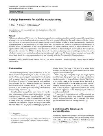
ProductionParts21.0Introduction andBackgroundProductionToolingTechnical Considerations forProduction ToolingConversion to AdditiveManufacturing1.1. Application OverviewFDM (Fused Deposition Modeling) additive manufacturinghas quickly become the technology of choice for the rapidproduction of manufacturing tooling. This design guide isfocused on design considerations for production tooling,but the vast majority of the principles and guidelines areapplicable to other additively manufactured parts as well.FDM production tools have many similar design anduse considerations as traditional tooling, although thetechnology provides greater design capability and OrientationDesignFreedomThis guide describes considerations for theadoption of additively manufactured tooling usingStratasys FDM technology and should be followedwhenever possible. Due to various best practices,deviations to this guide may be implemented atthe discretion of the individual user’s expertise.1.2. Process OverviewA generic FDM workflow is shown in Figure 1-2. For toolingwith specific requirements, the process order may differ. Itis advised that the designer coordinates and validates theoverall additive manufacturing process with the mechanicalengineer and/or materials and process engineer.1.3. ObjectivesDesign GuideThe objective of this guide is to provide design andbuild considerations for production tooling used inmanufacturing. The intent is to aid in bridging the knowledgegap between Design for Additive Manufacturing (DFAM)techniques and conventional tooling manufacturing bestpractices. This design guide aims primarily to provide: Additive design considerations for tool designers FDM design and process considerations for toolingFigure 1-1: The technical considerations for using additivemanufacturing in tooling.13D Model in CAD2Optimize in Computer AidedEngineering Software3Release per Approval Policy43D Print5Support Removal6Sanding & Finishing7Painting/Sealing8Final Inspection & MarkingAs requiredCAD, drawing, Insight build file (.cmb),materials and process documentation, etc.Prepare machine, load material, load job toselected printer, print, remove partsRemove support material from part using avariety of suited tools.As required. Smooth part surfaces per applicabledocumentation and prepare for secondarysealing or paintingAs required. Paint or seal per applicableindustry/corporate documentationFinal inspection (visual, dimensional, conformitychecks), tool markingFigure 1-2: FDM Production Tooling Workflow.
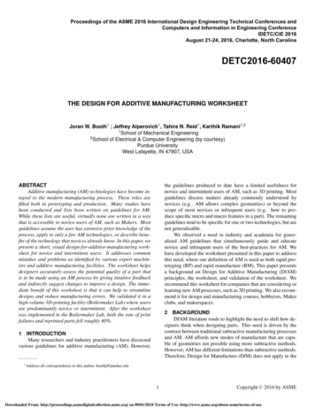
31.4. Approach1.6. Fused DepositionModeling ManufacturingProcess OverviewThis guide is broken into key sections that provide thenecessary information to efficiently and successfullyproduce, prepare and use FDM tooling. It offersdesign and material considerations to demonstrate theperformance of FDM tooling. Stratasys has workedwith industry leaders and tooling experts from severalmanufacturing industries to characterize and validateperformance and financial considerations as wellas overall equipment effectiveness. Key use casesand examples from these collaborative developmentefforts are provided, although partner identity isoften concealed to protect proprietary information.FDM is a Stratasys-patented additive manufacturingtechnology that builds parts layer by layer byheating and extruding thermoplastic filament. FDMuses a variety of standard thermoplastic resins.The FDM process begins by processing the CADfile using Insight or GrabCAD Print software,which comes with the system. This software allowsthe user to select build parameters like slice height,infill pattern and part orientation, providing thecapability for part customization. FDM machinesare capable of dispensing two materials duringthe printing process: the primary model materialthat makes up the final geometry and a secondarysupport material used as required to support materialoverhangs during future deposition layers. The supportmaterial is removed after the build. FDM filamentis wound onto canisters that feed material throughthe system to an extrusion nozzle, or “build tip.”One key partner was Volvo Trucks, who is arecognized leader in the automotive industry thatspecializes in the design and construction ofcommercial trucks. Volvo Trucks partnered withStratasys to implement FDM for lifting devices andancillary tooling (e.g. jigs, fixtures and trim tools).1.5. Axis TerminologyFor the following design principles, the figures maycontain axis information. It has been set (accordingto ASTM/ISO 52921) that the Z-Axis alwaysrefers to the printing direction of the machine.The X- and Y-Axes are simply named x and y.The build tip is heated by a liquefier, heatingthe material while depositing it in both primaryhorizontal axes (x, y) in a temperature-controlledchamber, following a numerically controlledtoolpath. Upon completion of each layer, thebuild platen moves vertically (z direction), to makeroom for the next layer to be deposited above.2178910411Design Guide53Figure 1-3: Main Components of an FDM Printer.61Model material spool2Support material spool3Build platen4Part5Part supports6Support material filament7Model material filament8Extrusion head9Drive wheels10Liquefier11Extrusion nozzle
41.7. Accuracy andTolerancesStratasys machine accuracies are stated as 0.005inch or 0.0015 inch/inch, whichever is greater. Actualpart accuracies will vary based on geometry, primarilydue to the thermal nature of the FDM process.Additional information on machine accuracycan be found on the FDM printer pages atStratasys.com. For production tooling that requiresgreater accuracy than can be achieved directly fromthe FDM 3D Printer, production of near-net shapetools, combined with machining is a viable option.Post-processing machine work is one option thathas proven extremely effective in mitigating theissues with inherent tolerance issues in currentFDM solutions. Machining of critical surfaces orhigh tolerance holes is a perfectly viable optionas tooling produced on FDM systems can bemachined similar to their plastic counterparts.1.8. Related Specifications ASTM F2971: Standard Practice forReporting Data for Test SpecimensPrepared by Additive Manufacturing. ISO/ASTM 52900: Standard Terminologyfor Additive Manufacturing – GeneralPrinciples – Terminology. ISO/ASTM 5292: Standard Terminologyfor Additive Manufacturing-CoordinateSystems and Test Methodologies. ASTM Y14.5: Dimensioning and Tolerancing.2.0Tool Design andConstructionConsiderationsThe unique form, fit, and function are keyrequirements when designing for FDM tooling. Additivemanufacturing enables unique design freedomsthat help fulfill these key requirements with fewerdesign restrictions commonly encountered withtraditional manufacturing. These design functionsinclude considerations for mechanical properties,materials, time, visual aesthetics and others.2.1. Engineering DesignRequirementsDetermining the critical elements of the design isimportant to the overall effectiveness of the tool.Critical elements such as working environment,measuring surfaces, tolerances, hard-mountingpoints, datums, static and dynamic loading, handling,tool life expectancy and even storage will affect theway that FDM tools are designed. Having a definedcriteria for what is expected of the tool will help inmaking the most economical and effective tool forits use. FDM will sometimes be a great option for aproduction line tool and other times it might just be thequickest path to having something that will work whilea more robust solution is developed or fabricated.2.2. Material ConsiderationsDesign GuideDeciding on tool material should be the firststep in the FDM tooling design process. Thisdecision can be simplified by considering thedesign requirements that were previously set forthe tool. The most common materials used fortooling applications are shown in Table 1.Other materials are offered but this group of materialsis the most suitable for a great majority of toolingapplications and uses. However, it can be useful toexplore the other options in the case of an abnormalset of requirements. A complete list of StratasysFDM materials and their material properties canbe found at Stratasys.com/fdm-technology.
5Material Property ConsiderationsMaterialLoadingTemperature ResistanceChemical eLowFDM Nylon 12 LightModerateModerateFDM Nylon 12 Carbon Fiber (CF)HeavyModerateModerateULTEM 9085 resinHeavyHighHighULTEM 1010 resinHeavyHighHighTable 1Tool life will depend heavily on how and where theyare used as well as any other environmental factors.2.2.1. In-Service Temperature ConsiderationsThe in-service temperature of plastics is generally themajor determining factor that decides their usage.The materials suggested in this design guide coverthe entire temperature range of the FDM materialsuite. Operating conditions for FDM tooling shouldnot exceed a temperature 50 F (28 C) below thematerial’s heat deflection temperature (HDT) and25 F (14 C) below the glass transition temperature(Tg). FDM materials will survive for only very shortperiods above these limits. However, the FDM processdoes build in some residual stresses which may causethe tool to warp once the temperature approachesand exceeds the HDT or Tg of the material. Thevalues for HDT and Tg can be found on the respectivematerial pages at Stratasys.com/materials.2.2.2. Chemical Compatibility ConsiderationsDesign GuideThe chemical composition of polymers will determinetheir reaction to different chemical agents. Anoverview of the chemical compatibility for all FDMmaterials can be found here. Also, the plasticsthat Stratasys uses will behave exactly as theircounterparts in other manufacturing methods. Thereare many chemical compatibility charts availablefrom these manufacturers. A brief synopsis for therecommended materials can be found below.ASA is degraded by concentrated acids, aromaticand chlorinated hydrocarbons, esters, ethers andketones. Acetone and MEK are going to be the mostcommon cleaning materials that fall under thosecategories. Nylon is susceptible to strong acids,phenols, alcohols, and halogenated hydrocarbons.One typical example is isopropyl alcohol.Both ULTEM materials are extremely resistant tomost chemicals with the exception of phenols.The most notable example of a phenolic solvent ischloroform, so it would have to be a highly abnormalsituation for ULTEM to be chemically ruled out.The only exception is ULTEM 9085 resin, as it is aco-polymer so its chemical resistance is slightly lowerthan ULTEM 1010 resin for certain categories.Another compatibility issue to evaluate with plasticsis their resistance to ultra-violet (UV) radiation.Fortunately, ASA and ULTEM are both naturally moreresistant than most plastics. FDM Nylon 12 and FDMNylon 12CF , however, are not UV-stable and aresusceptible to this type of degradation if left outdoorspermanently. If used indoors or in environmentswith minimal UV exposure, they will hold up andperform as expected for extended periods of time.Lastly, many plastics are susceptible to waterabsorption. Moisture weakens the polymericstructure and degrades mechanical properties incertain polymers. Of the recommended materials,FDM Nylon12, FDM Nylon 12CF and PC are themost water-sensitive materials and may see someslight property loss in wet environments. The otherthree recommended materials (ASA, ULTEM 1010resin and ULTEM 9085 resin) naturally saturatefrom moisture in the air but their absorption limithas very little to no effect on their performance.2.2.3. Material Creep Behavior ConsiderationsAn important factor to consider when choosinga material is creep, a property that nearly allthermoplastics have. Creep causes plastics to slowlydeform when they are under long-term loading;however most tooling is not loaded long enoughfor this to happen. A major example of where thiscan occur is during storage. If the tool is stored in asituation where it sees load for an extended period oftime, its high-tolerance dimensions can be affected.
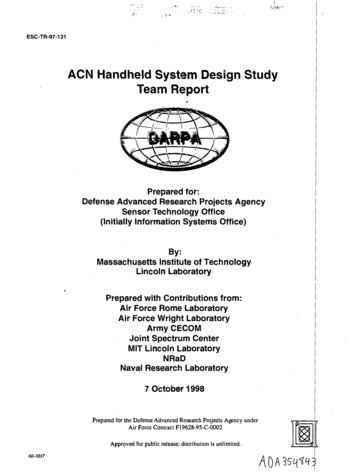
62.3. Design forFDM ManufacturingConsiderations2.3.1. Anisotropic Property ConsiderationsAnisotropic part strength occurs when parts havephysical properties that vary in different orientations.It is an issue with additively manufactured parts dueto the layer-by-layer material deposition to createthe part. The bond strength between layers is thedetermining factor for z-strength which is alwaysthe weakest. The highest values for tensile strengthwill be in the path of the tool head (x-y plane).FDM Nylon 12CFUltimateTensile Strength4,990 psiBuild orientation, part geometry and pre-processingtechniques can all be used to account for and mitigatethese process-specific strength characteristics.Avoid designing sharp deflection points anddisturbances by using chamfer and radii features.The larger the radius or chamfer it is possibleto add to a tool, the better it will perform.Stratasys provides different strength values per materialfor each build orientation. This specification data isavailable for all FDM materials and should be usedfor material comparison and selection. This datacan be found at Stratasys.com/materials/search.Z10,960 psi2.3.2. Static vs. Dynamic Loading ConsiderationsDesign GuideWhen taking into account applied tension,compression, bending, shear and torsional loadingconditions for FDM tooling, a direct load path isdesired. Designing the shortest load path possiblewithin the constraints of the application is also ideal.FDM is uniquely suited to odd configurations ofstructures and complex geometries so designersshould take advantage of this ability when consideringways to mitigate loading issues. Topology optimizationcalculates and shows the distribution of materialwithin a user defined boundary based on the designrequirements. It can be applied to parts to take fulladvantage of the geometric freedom FDM provides.As mentioned earlier, creep can be a major factorwhen dealing with plastics. Dynamic loading can havesimilar issues if the load nears the yield point of theplastic. Abrasion from repeat motion can also be anissue. One way to deal with this is to design in hardmounting and wear points through the use of metallicor ceramic inserts. The location can be manufacturedto net size if a low tolerance is available or a locationfeature can be added for post-processing to machinein areas for inserts. Inserts can also be useful to addstiffening members of other materials to resist thedynamic load or overload from high static forces.X and YZYXFigure 2-1: Anisotropy results in lower strength values in the z-plane.2.3.3. Time to FabricateSimilar to conventional manufacturing processes,additive manufacturing has aspects that must beconsidered when planning production. Build orientationduring the printing process is a key factor for theamount of time it takes to print a tool. The addition ofmaterial in the Z direction takes longer than additionof material in the X-Y plane. The extrusion head ofmost FDM platforms is significantly faster when layingdown material in-plane as opposed to repeateddeposition followed by Z-direction adjustment. Whendetermining build orientation of a part, the amountof time allowed for production can be a major partof the design requirements although it is generally a
7by-product. To reduce the amount of time necessary, itis suggested to orient the tool so most of the materialis in the X-Y direction. This is also beneficial for overallpart strength. Table 2 shows how build orientationaffects print time as well as model and support materialconsumption. Figures 2-2 through 2-4 show thecorresponding physical orientation on the build tray.Figure 2-2: Orientation 1.Another consideration is support material. Each time anFDM system switches from model material to supportmaterial it goes through a series of steps. Althoughthese steps only take roughly 30 seconds, they canadd up if the process has to be repeated many times.Depending on the size of the tool this can becomea major factor in the time for build completion.Figure 2-3 Orientation 2.One design technique that can be used to mitigate theuse of support material is the use of self-supportingangles ( 45 from the build platen) for interior and exteriorfeatures. Horizontal holes (relative to the X-Y build plane)as in Figure 2-5 will have poor resolution due to stairstepping. A slightly undersized diamond shape pilothole will print without support material and can be usedin place of circular holes and then reamed to size as asecondary operation. Notice the feature on the far rightin Figures 2-6 and 2-7 used self-supporting angles inboth horizontal axes resulting in no support material use. Figure 2-4 Orientation 3.Figure 2-5: Poor resolution of horizontallyprinted holeOther factors such as material, slice height and interiorfill density can also be changed to optimize build timeduring the processing stage after the design is complete.Build Orientation ExamplesOrientationPrint TimeModelMaterial (in3)SupportMaterial (in3)1(Figure 2-2)6h 23m11.73.02(Figure 2-3)12h 16m12.44.23(Figure 2-4)12h 14m12.74.2Figure 2-6: Example with internal and external features in CADTable 2Design Guide2.3.4. AestheticsAn often overlooked characteristic of the design phaseis the necessary aesthetics of the final product. TheFDM process naturally generates a layered look with asurface roughness of 500-600 µin Ra in the X-Y planeand mostly flat surfaces in the Z direction. Any surfacesthat have an angle in the Z direction are subject to“stair-stepping” (shown in figure 2-8), which can drivethe Ra up into the 1,200-1,500 range based on layerthickness and geometry of the surface. If the desiredFigure 2-7: Example with internal and external featuresshowing support material (shown in orange)
8surface needs secondary finishing, trials and methodshave been developed in order to sand, seal and paintFDM parts with a final surface finish of 10 µin Ra.For more information regarding finishing processes,see the Stratasys website Finshing Processes.Surfaces that have high aesthetic requirements shouldbe oriented in the vertical direction if possible. Facesthat are flat can also be oriented perpendicular tothe XY build plane to eliminate stair-stepping. Figure2-9 shows sloped surfaces starting at 5 degreesfrom horizontal all the way to vertical (45 ) and howthe surface finish is affected by the build angle.123Figure 2-8: Visual representation of stair stepping — as the angle from verticalincreases, surface roughness increases.Slice height is an important factor when consideringsurface finish. Using a smaller slice height producesa higher resolution part with a better surface finish.Larger slice heights produce more visible layerlines. The steeper the angle becomes, the less thiscan be seen. Figure 2-10 shows the differencebetween larger and smaller slice heights.Low Resolution Thicker LayersLower resolution parts have a largerslice height resulting in thicker layers.This creates a large horizontal stepbetween layers and producesa rougher edge.Higher Resolution Thinner LayersHigher resolution parts have a smallerslice height resulting in thinner layers.This decreases the horizontal stepbetween layers and produces asmoother edge.Figure 2-9: Effects of stair stepping on surface finish.Figure 2-10: Low vs. high resolution.Design GuideToolpath seams also have an impact on aesthetics.A seam is defined as the start and stop location ofa contour tool path. Seams can create a blemishon the surface where they occur. Placement ofseams is important when processing in Insight forthis reason. A seam should be placed on the leastimportant side of the part or a face where they caneasily be smoothed by light sanding after the part hasbeen built. Figures 2-11, 2-12 and 2-13 show threedifferent examples of seam placement methods.Figure 2-11: Seam placement on edge.Knowing surface finish requirements up frontshould inform how the part is designed aswell how it is processed. Choosing the correctslice height and build orientation are criticalto achieving the desired surface finish.Figure 2-13: Random seam placement.Figure 2-12: Aligned seam placementin center.
92.4. Leveraging DesignFreedomFDM offers an unprecedented level of designfreedom compared to traditional manufacturingprocesses. While many benefits for using FDM liein cost and time reduction and mitigation of supplychain issues, the true value is in leveraging thedesign freedom. This freedom allows tool designersto produce parts with higher levels of performanceand functionality than what is possible with othermanufacturing processes. This level of functionalityis up to the creativity of the designer. Unconstrainedthinking has led to the creation of parts that performcomplex interactions to achieve a simple goal.Figure 2-14: CAD model of bell crank example with multiple infill. patterns2.4.1. Weight and Durability ConsiderationsThe FDM process gives the designer freedom to makelarge parts without requiring large amounts of materialand the weight associated with those large parts. Thisis accomplished through the use of variable fill patternsfor the internal structure of the tool. The CAD model ofthe bell crank example part shown in Figure 2-14 wasmodeled with six different solid bodies to representthe areas that will have different infill patterns. In orderto retain a press fit bearing, the red features wereprinted solid. To add strength, the internal ribs shownin yellow were printed with a sparse double dense infillat 30% density. The rest of the body shown in greenwas printed with a sparse infill at 60% density. To addrigidity, the outer shell of the tool was thickened byadding additional contours on the edge of the part.The actual printed part can be seen in Figure 2-15.Using variable fill patterns will affect the moment ofinertia of the part and is something to be considered intools that are in motion or subject to dynamic loads.Figure 2-15 Printed bell crank example with multiple infill patterns.Design Guide2.4.2. Tool Assembly ConsolidationIn many cases, it is possible to consolidate what wouldotherwise be an assembly of multiple components intoa single component. For example, because it doesnot impact the cost greatly, a lifting device lifter canbe printed with its attachment brackets integratedas seen in Figure 2-16. In general, components ofan assembly should be combined when it does notviolate any engineering constraints such as materialperformance, part cost, or lead time. Additionally,the decision to combine parts must be evaluatedfor the ability to select a build orientation that meetsrequirements for each individual component.Figure 2-16: Part assembly consolidation resulted in a 96% reduction oftooling assembly components.
102.4.3. Part Bonding ConsiderationsBonding of FDM tooling has many of the sameissues as bonding of generic plastics, with a fewcaveats. The layered surface produced by the FDMprocess creates additional mechanical bonding foradhesives but the surface will still need to be cleanedto assure no debris is caught in the bond area.Adhesive gaps of 0.005 inch are standard andallow for material clearance from part to part witha solid bondline control. Thermoplastic materialsdo not have a large functionalized surface so theirchemical bonds with thermoset adhesives canbe greatly increased by using an activator priorto bonding. With that in mind, most thermosetadhesives suitable for plastics and the temperaturerequirements of the application will operate effectivelywith FDM tooling. For most practical applications,Stratasys tends to use epoxy-based adhesives.Joint design is again made easier with the designfreedom of FDM. The connection surface canbe as simple or as complicated as desired. Anexample of two parts joined together using roundjoint connections is shown in Figure 2-17. Adetailed view showing the desired clearances isshown in Figure 2-18. Dovetail, butterfly or lapjoint are all good options for joint connections aswell. The same clearances apply to those joints.Another bonding method for FDM tooling is hotair plastic welding. Hot air welding uses the samematerial as the FDM tool to join the sectionstogether. The strength of the joint can be increasedby using adhesives in conjunction with the weldingprocess. Coating the interior keeps the epoxywithin the tool and away from the outer surface.When designing a tool to be hot air welded it isadvisable to incorporate a chamfer, as shown inFigure 2-19, allowing for deeper weld penetrationand more material contact than just a surfaceweld. Much like metal welding, the more materialadded to the joint, the stronger the weld will be.Figure 2-17: Assembly utilizing circular tab and slot joints.Figure 2-18: Recommended clearances between male and female features.60 Design GuideFor more information regarding bonding please refer toComparison of Bonding Methods of FDM Materials.Figure 2-19: Chamfer added to parts for better penetration during hot airwelding.
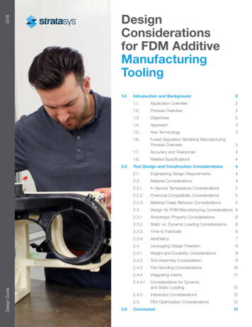
112.4.4. Integrating InsertsAs mentioned in section 2.3.2, hardware may beadded to FDM production tooling in a secondaryoperation. For example, threaded inserts, bushings,magnets and other hardware can be inserted intofinished parts. These inserts can be secured witha variety of processes including but not limited to:heat set, press fit, tapping/threading and bonding.Threaded inserts are a great solution for fasteningmultiple parts together as well as adding toolingcomponents like hardened rest pads or clamps toa printed tool. There are many different types ofthreaded inserts available to choose from dependingon how the insert is expected to perform in the tool.In addition to design requirements, labor should alsobe taken into account. Traditionally these inserts areused for injection molded parts or in various metalapplications, however they work just as well in FDMparts. Inserts can be broken down into five generalcategories with each category having multiple styles.1. H eat-Set/Ultrasonic – easy installation andhigh torque-out and pull-out resistance2. S elf-Tapping – higher pull-out strengththan heat-set/ultrasonic3. P ress-In – quick and easy installation butpoor torque-out and pull-out resistance4. P ress-In Expansion – quick and easy installationbut poor torque- and pull-out resistance5. H elical – labor-intense installation buthigh torque- and pull-out resistancerefer to this style of insert with a dual name becauseit can be pressed into thermoplastics with heat orultrasonic vibrations. Stratasys recommends heatinstallation as the preferred method of installation dueto the simplicity and consistency of the process.There are options for heat installation equipmentdepending on budget and/or the volume of insertsto be installed. An economical, low-cost and lowvolume choice would be to purchase a simple heatsoldering gun and the corresponding tip sizes forthe inserts that will be installed. A second, moreexpensive option is a manual heat installation driver.These machines control heat, pressure and depthduring the installation process but cost upwardsof 1,000. They also provide a better means ofinstalling the insert co-axial to the pilot hole as theplunger is normal to the build plate. Further measurescan be taken to guarantee installation accuracy bycreating fixturing that can attach to the build plateto locate the part. Figure 2-21 shows a manual heatinstallation driver during the installation process.Stratasys recommends following the threaded insertmanufacturer’s design guidelines for hole size andgeometry. Keep in mind these are only recommendedvalues so they may need to be adjusted slightly basedon installation results. These manufacturers also havetroubleshooting guides for installation issues andhow to address them. It is recommended to followtheir procedures to ensure proper installation of theinserts. Figure 2-22 shows heat set threaded insertsintegrated into the tool. For details on installation, seethe Best Practice: Inserting Hardware into FDM Parts.PLUNGERHEA DS ET I NS ERTF DM PA RTBU I L D PL ATEDesign GuideFigure 2-20: Threaded inserts for plastics.From an ease-of-installation and performancestandpoint, Stratasys recommends heat-set/ultrasonic style inserts. Although they takelonger than press-in style inserts to install andalso require additional installation equipment,they offer much better performance in termsof torque-out and pull-out resistance.Figure 2-21: Heat insert driver machine.There are no physical differences between heat-setand ultrasonic threaded inserts. Insert manufacturersFigure 2-22 Fixture utilizing brass heat set.
122.4.4.1 Considerations for Dynamicand Static LoadingDesign in hard mounting points through the use ofmetallic or ceramic bushings. Holes can be designedand printed in the part if there are not tight tolerancerequirements. If hole location ac
Manufacturing Design uide 2 1.1. Application Overview FDM (Fused Deposition Modeling) additive manufacturing has quickly become the technology of choice for the rapid production of manufacturing tooling. This design guide is focused on design considerations for production tooling, b