Transcription
NASA/TM—2016–219344High Temperature Thermoplastic AdditiveManufacturing Using Low-Cost, OpenSource HardwareJohn M. GardnerLangley Research Center, Hampton, VirginiaChristopher J. StelterLangley Research Center, Hampton, VirginiaEdward A. YashinUniversity of Michigan – Dearborn, Dearborn, MichiganEmilie J. SiochiLangley Research Center, Hampton, VirginiaOctober 2016
NASA STI Program . in ProfileSince its founding, NASA has been dedicatedto the advancement of aeronautics and spacescience. The NASA scientific and technicalinformation (STI) program plays a key part inhelping NASA maintain this important role. CONFERENCE PUBLICATION.Collected papers from scientific andtechnical conferences, symposia, seminars,or other meetings sponsored orco-sponsored by NASA.The NASA STI program operates under theauspices of the Agency Chief Information Officer.It collects, organizes, provides for archiving, anddisseminates NASA’s STI. The NASA STIprogram provides access to the NTRS Registeredand its public interface, the NASA TechnicalReports Server, thus providing one of the largestcollections of aeronautical and space science STIin the world. Results are published in both nonNASA channels and by NASA in the NASA STIReport Series, which includes the following reporttypes: SPECIAL PUBLICATION. Scientific,technical, or historical information fromNASA programs, projects, and missions,often concerned with subjects havingsubstantial public interest. TECHNICAL TRANSLATION.English-language translations of foreignscientific and technical material pertinent toNASA’s mission. TECHNICAL PUBLICATION. Reports ofcompleted research or a major significantphase of research that present the results ofNASA Programs and include extensive dataor theoretical analysis. Includes compilations of significant scientific and technicaldata and information deemed to be ofcontinuing reference value. NASA counterpart of peer-reviewed formal professionalpapers but has less stringent limitations onmanuscript length and extent of graphicpresentations.TECHNICAL MEMORANDUM.Scientific and technical findings that arepreliminary or of specialized interest,e.g., quick release reports, workingpapers, and bibliographies that containminimal annotation. Does not containextensive analysis.CONTRACTOR REPORT. Scientific andtechnical findings by NASA-sponsoredcontractors and grantees.Specialized services also include organizingand publishing research results, distributingspecialized research announcements andfeeds, providing information desk and personalsearch support, and enabling data exchangeservices.For more information about the NASA STIprogram, see the following: Access the NASA STI program home pageat http://www.sti.nasa.gov E-mail your question to help@sti.nasa.gov Phone the NASA STI Information Desk at757-864-9658 Write to:NASA STI Information DeskMail Stop 148NASA Langley Research CenterHampton, VA 23681-2199
NASA/TM—2016–219344High Temperature Thermoplastic AdditiveManufacturing Using Low-Cost, OpenSource HardwareJohn M. GardnerLangley Research Center, Hampton, VirginiaChristopher J. StelterLangley Research Center, Hampton, VirginiaEdward A. YashinUniversity of Michigan – Dearborn, Dearborn, MichiganEmilie J. SiochiLangley Research Center, Hampton, VirginiaNational Aeronautics andSpace AdministrationLangley Research CenterHampton, VA 23681October 2016
AcknowledgmentsThe authors would like to acknowledge the efforts of Robert Andrews and GaryWainwright of NASA Langley Research Center for part fabrication and NASA Internships,Fellowships and Scholarships (NIFS) students Isabel Cleff, Maria Moreno, and Lucia Korpas forassisting with printing test samples.This report is available in electronic form athttp://ntrs.nasa.gov
IntroductionAdditive manufacturing (or 3D printing) via Fused Filament Fabrication (FFF), alsoknown as Fused Deposition Modeling (FDM), is a process where material is placed in specificlocations layer-by-layer to create a complete part. Printers designed for FFF build parts byextruding a thermoplastic filament from a nozzle in a predetermined path [1]. Originallydeveloped for commercial printers, 3D printing via FFF has become accessible to a much largercommunity of users since the introduction of RepRap printers [2]. These low-cost, desktopmachines are typically used to print prototype parts or novelty items [3]. As the adoption ofdesktop sized 3D printers broadens, there is increased demand for these machines to producefunctional parts that can withstand harsher conditions such as high temperature and mechanicalloads [4, 5]. Materials meeting these requirements tend to possess better mechanicalproperties and higher glass transition temperatures (Tg), thus requiring printers with hightemperature printing capability [6]. Additional print environment specifications are needed inorder to produce quality parts with these high temperature materials. The most critical of thesespecifications is maintaining a high part temperature, preferably at or near the Tg of the material,during the printing process. Doing so reduces the amount of warping that occurs in the partduring printing and facilitates interlaminar adhesion between the print layers [7]. Without theseenvironmental conditions, the high temperature 3D printed parts will be functionally limited oruseless. Additionally, these materials require extrusion temperatures upwards of 400 C [6].While industrial machines (e.g., Stratasys Fortus 450mc) are equipped to print a wide variety ofmaterials with high Tgs such as polyetherimides (PEI or Ultem ) [8], desktop sized printers arelimited to lower temperature filaments such as polylactic acid (PLA) and acrylonitrile butadienestyrene (ABS) [9]. Currently, there are very few desktop printers with the advertised capabilityof high temperature thermoplastic printing [4, 10, 11]. Most desktop 3D printers are notdesigned to maintain the necessary environment to sustain the proper part temperature duringthe printing process and/or the printer components cannot withstand the elevated temperaturesrequired during printing. A system has been developed based on a commercially availabledesktop 3D printer that is capable of producing high quality, warp-free parts from hightemperature thermoplastics. This report outlines the problems and solutions, and includes adetailed description of the machine design, printing parameters, and processes specific to hightemperature thermoplastic 3D itrile Butadiene StyreneFused Deposition ModelingFused Filament lactic acidGlass Transition Temperature1
Printer DevelopmentDesign SpecificationsAs described above, a central challenge to high temperature printing is maintaining thepart temperature during printing. To accomplish this, industrial machines employ a convectionoven around the build volume of the printer to maintain the proper build environment [12]. Thisis not a practical solution on desktop machines for a variety of reasons, including the overalldimensions of the machine and the design of the gantry and extruder systems. Therefore, thesystem developed and described herein uses directed infrared (IR) heating to focus energy onand control the temperature of only a printed part rather than the entire machine. Doing sokeeps the printing environment at a low enough temperature for many of the machinecomponents to maintain structural integrity and function properly. However, some stockcomponents such as electronics, stepper motors, ABS printed machine parts, and hot ends stillrequired modification to ensure survivability and compatibility with the elevated temperatures themachine is exposed to during printing.Machine DesignStarting with the stock Lulzbot Taz 4 3D printer (Aleph Objects, Loveland, CO) (Figure1a), a number of modifications were made to enable high temperature thermoplastic printing(Figure 1b). These modifications are described in detail below.Electronics and Machine EnclosureAn enclosure system was constructed around the machine in order to retain heat andprevent drafts from affecting the printed part. The enclosure consisted of an aluminum framewith cardboard foam core side walls, and included a door and window for machine access andviewing while the printer is operating. A rubber seal was placed around the door to prevent heatloss. Figures 2a and 2b show a model of the printer enclosure. Figure 2c shows the as-builtenclosure without the front window installed. To avoid overheating the control board (Rambov1.2), the electronics box normally attached to the side of the printer was removed and placedoutside of the enclosure. Cabling was routed through the sidewall of the printer and the lengthsof the wires were adjusted where needed. Figure 3 shows this set-up.Printer Part Material UpgradesThe base machine contains many printed parts built from ABS. The Tg of this materialranges from 85 to 110 C, which is lower than the temperature the parts may be subjected toduring high temperature printing. To prevent warping or failure of the ABS parts in theenclosure, all parts made from ABS were replaced with parts made from a material with a higherTg: initially, polycarbonate (PC) (Tg 147 C). Since PC is susceptible to stress cracking whenexposed to hydrocarbons, the PC parts were eventually replaced with Ultem (Tg 218 C) partsprinted on the machine.High Temperature Hot EndDuring printing, filament is deposited onto the print bed using the cold end to applypressure and push the material through the hot end where it is heated and extruded through asmall nozzle. The locations of the hot end and cold end are shown in Figure 4. The stock hotend (nozzle) on the machine is only rated for 300 C due to limitations of the thermistor as well2
as the ABS cold end. This is below the required temperature for most high temperaturematerials. Therefore, a new hot end (E3D-v6 1.75 mm Universal, E3D, Oxfordshire, UK) waspurchased and installed that allows for temperatures above 400 C. The kit included the nozzle,heat sink, thermal break, and fan shroud that were used in the modified machine. In addition, a24V fan (for compatibility with the existing electronics) and 500 C thermistor (B3 Innovations,Cleveland, OH) were purchased separately and installed on the machine. No modificationswere needed to integrate the new thermistor and fan into the E3D hot end. A counter-boredhole was added to the cold end mount to allow the hot end to sit flush with the cold end. The 2mm inner diameter tubing included with the kit was installed per the instructions and then cutflush with the top of the hot end.IR Heating LampsMaintaining part temperature during printing is critical to a successful print. Therefore,twelve 35 W halogen light bulbs (Sunlite, Brooklyn, NY) were installed surrounding the buildvolume. Figure 5 shows the arrangement of the lights in the machine. Because the buildplatform moves in the y-direction during the print, the lights were arranged to ensure amplecoverage of the part regardless of the position of the y-axis. The angle of the lamp relative to they-axis was staggered by 12 degrees starting perpendicular to the y-axis and going towards thecenter of the machine. Four brackets each holding three lamps were hard mounted to themachine frame. Figure 6 shows the lamps mounted in the machine.Stepper Motor CoolersLinear movement of the machine is accomplished using stepper motors. There are atleast five stepper motors installed on the machine that have a maximum service temperature of55 C. The typical air temperature of the enclosure is around 62 C. Complications such asmissed steps, wear, and total failure of the motor will result if the motors are run above theirmaximum service temperature. Active cooling using forced air convection was added to thesystem to prevent these issues. A cooling shroud was designed to direct the air flow around theoutside of the motor. It was installed around each of the motors and sealed using hightemperature silicone (VersaChem Mega Copper Silicone, ITW Consumer, Hartford, CT)(Figures 7a and 7b). Figure 7c shows the cooling shroud used in the prototype system andpoints out the flow channel for directing air around the motor. The design of the cooling shroudwas tailored to the dimensions of the stepper motor. Figure 8 shows the pneumatic schematicof the cooling system. A single pressurized air line is fed into the system and then distributedamong all of the motors. The exhaust from the cooling shrouds is then fed back outside theenclosure and released into the environment. Input pressure (90 psi max) is adjusted to ensuresufficient cooling.Filament StorageSome printing materials are known to be hygroscopic, which can cause porosity issuesduring printing. When a filament with adsorbed moisture is used for printing, trapped watervapor forms bubbles during extrusion from the hot end. To prevent this, a special filament box(Filabot, Barre, VT) with desiccant added to keep the humidity at around 15-20% was used tostore the filament. Through-wall connectors and polytetrafluoroethylene tubing were used toprovide a path for the filament to travel from the filament box into the enclosure and then to thecold end without being exposed to the ambient environment. Figures 9a and 9b show thefilament box and guide tube.3
ElectronicsAdditional electronics were required to power the IR heating lamps installed on themachine. The IR heating lamp electronics were independent of the control board because ofthe high load requirements. Figure 10 shows the schematic of the enclosure lamp electronics.Standard outlet electrical power (120VAC 60Hz) was fed into a power bus and split into twoseparate lines. These lines were then routed through a solid state relay and into another powerbus where they were split an additional six times and each routed to a lamp. Power and logicfor the relays were supplied by the control board via expansion pins. As with the control board,the relays and power bus were located outside of the enclosure as shown in Figure 3. All lamppower was fed to a common ground.FirmwareChanges were made to several files of the firmware (Marlin) so that the new modifiedprinter would function properly. The maximum allowable hot end temperature was changed in“configuration.h” from 300 C to 500 C to reflect the new high temperature configuration. A newtemperature table was added to “thermistortables.h” to allow the controller to interpret thereadings from the 500 C thermistor. Two machine commands were added to “marlin main.cpp”in the form of M codes (M740 and M741) to turn the IR heating lamps on and off when required.The process was written with a 0.5 s delay between the actuation of each relay as a safetymeasure to prevent the circuit from becoming overloaded. The new pins for operating therelays were added to “pins.h” and defined in “marlin main.cpp”.Printing ParametersPrinting parameters for a given material can vary depending upon factors such as partgeometry and machine-to-machine variations. Some general printing parameters for Ultem 1010 were developed and are listed in Table 1.Other ModificationsAdditional modifications were made to the base printer for ease of use and to reducevariables in the machine. A four-point conductive pad bed leveling system was added toeliminate the need to manually level the bed. The bed leveling system design from a LulzbotTaz Mini was used with minor modifications made to the conductive touch pads for clearancepurposes. A dual nozzle system was also utilized on the machine to allow for multi-materialprinting. All high temperature printing and bed leveling were done using the forward mostnozzle.Printing ProcessA step-by-step guide to printing high temperature materials is described below. Individualsteps and the sequence in which they are carried out will vary depending on the machine,printing environment, and material. Parts using the procedure below were printed with Ultem 1010, 1.75 mm diameter filament purchased from Stratasys (Eden Prairie, MN).1. Remove a length of filament from its original container and transfer it onto a new spoolcapable of withstanding temperatures of at least 161 C. A cardboard spool with a metalcore is a suitable choice.2. Place the filament in a convection oven at 161 C for one hour to remove surfaceadsorbed moisture.4
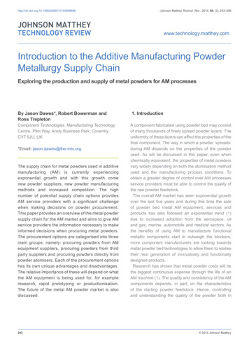
3. Apply a thin layer (3-4 passes) of Elmer’s Disappearing Purple glue stick (Westerville,OH) directly onto the glass print bed.4. Pre-heat bed to print temperature ( 162 C). It is recommended that this step becompleted while the material is in the oven, as the bed can take 15 minutes to reachtemperature.5. Begin heating the nozzle to print temperature (345-375 C).6. Once the filament has dried, remove it from the oven while still hot and load it into theprinter. Allow a bit of material to extrude from the nozzle.7. Remove the excess material from the nozzle and cool the nozzle to about 200 C. Whilecooling, scrub the nozzle with a wire brush until the temperature reaches about 260 C.This will remove any residual Ultem 1010 on the nozzle and prevent a meniscus fromforming at the nozzle outlet which could lead to bed leveling errors.8. Perform the homing and bed leveling procedures.9. Load desired g-code and begin the print.10. At the completion of the print, remove the part from the bed using a spatula or other thin,flat tool. The bed may be allowed to cool to near ambient temperature before the part isremoved to ensure even cooling throughout the part. Note however that doing so willmake the part more difficult to remove from the bed.Some modifications to the machine readable code (g-code) that are necessary to ensure asuccessful print are described below. Ultem 1010 tends to ooze from the nozzle while attemperature, so a nozzle priming step (20 mm) is added before the first line is printed.Commands are added for turning the lamps on at the beginning of the print and then off at theend. The print bed temperature on the machine runs a few degrees below the set point, so thebed temperature is removed from the g-code and set prior to starting the print (Step 4). All otherparameters (e.g. nozzle temperature, print speed, etc.) are controlled through normal means inthe g-code. Steps 7 and 8 are performed by the user in this procedure, but could be automatedwith a few modifications to the machine.Design Validation and DiscussionAs an initial test to determine the effectiveness of the modifications made to the system,functional parts with a variety of dimensions and geometries were printed with Ultem 1010.Figure 11 shows a comparison of an Ultem 1010 part printed with and without the IR heatinglamps and enclosure system. The parts printed without the IR heating lamps showed significantprint quality issues with interlayer adhesion (Figure 11a) and warping (Figure 11b). Multipleattempts were needed to print each part as they often became detached from the build plateduring printing. These issues were significantly reduced or eliminated when the IR heatinglamps and enclosure were employed. Figures 11c and 11d show these parts. No delaminationwas present in the printed parts. Additionally, no warping was observed at the edges of theparts.Some general observations were made on the effect of printing parameters on partquality. Utilizing lower nozzle temperatures typically led to more dimensionally accurate prints.Higher bed temperatures resulted in a further reduction of warping, but at the cost of increasedstart-up time to allow the bed to reach temperature. The effects of these parameters on partsprinted from Ultem 1010 are consistent with the effects of these parameters on lowertemperature materials.5
SummaryThe necessary modifications, processes, and procedures for printing high temperaturethermoplastic materials using low cost, open source hardware were described. The processwas demonstrated using an Ultem 1010 material system and was shown to produce largeprinted parts with no evidence of warping or delamination. While the system used a Lulzbot Tazmachine as the base printer, the modifications described are not unique to this machine typeand could be implemented on other low-cost 3D printer systems.The use of trade names or manufacturers does not constitute an official endorsement of suchproducts or manufacturers, either expressed or implied, by the National Aeronautics and SpaceAdministration.References[1] S. S. Crump, Apparatus and method for creating three-dimensional objects, US Patent5,121,329, issued June 9, 1992.[2] R. Jones, P. Haufe, E. Sells, P. Iravani, V. Olliver, C. Palmer, A. Bowyer, “RepRap – thereplicating rapid prototype,” Robotica 29 (2011) 177-191.[3] C. Barnatt, 3D Printing, second ed., ExplainingTheFuture.com, 2014.[4] W. Hipolite, “INDMATEC Launches the PEEK 3D Printer – First FDM 3D Printer for PrintingHigh Temperature Polymers,” /, RetrievedJune 26, 2015.[5] S. Goehrke, “CF-Nylon and Ultem 9085: 3D Printing Material Launches from 3DXTECHPromise Strength, Set to Continue Launching,” s/, Retrieved April 5, 2016.[6] A. El-Gizawy, S. Corl, B. Graybill, “Process-induced properties of FDM products,”Proceedings of the ICMET, Paris, France, July 25-29 (2011).[7] T.M. Wang, J.T. Xi, T. Jin, “A model research for prototype warp deformation in the FDMprocess,” Int. J. Adv. Manuf. Technol. 33 (2006) 1087-1096.[8] FDM Thermoplastics, http://www.stratasys.com/materials/fdm, (n.d.) Retrieved June 15,2016.[9] B. M. Tymrak, M. Kreiger, J. M Pearce, “Mechanical properties of components fabricatedwith open-source 3-D printers under realistic environmental conditions,” Mater. Design 58(2014) 242-246.[10] 3dison AEP, http://en.3disonprinter.com/product-AEP.php, (n.d.) Retrieved June 15, 2016.[11] System 30M, http://www.hyrel3d.com/core-suystems/system-30m/, (n.d.), Retrieved June15, 2016.[12] W. Swanson, P. Turley, P. Leavitt, P. Karwoski, J. LaBossiere, R. Skubic, High temperaturemodeling apparatus, US Patent 6,722,872, issued April 20, 2004.6
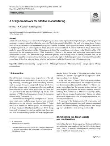
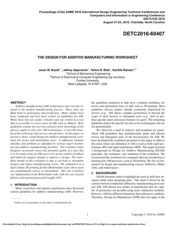
Figures and TablesFigure 1: (a) Stock Lulzbot Taz 3D printer. (b) Printer after high temperature modifications.Image Credit: NASA.Figure 2: (a) 3D model of enclosure frame with door closed and (b) open. (c) Completedenclosure with front window. Image Credit: NASA.7
Figure 3: Image showing location of electronic components including IR heating lamp groundand power bus, relays, and Rambo electronics board. Image Credit: NASA.Figure 4: Stock FFF set-up showing the location of the hot and cold ends. Image Credit:NASA.8
Figure 5: Layout of IR heating lamps with respect to the print bed. Image Credit: NASA.Figure 6: Image of IR heating lamp unit identifying the key components. Image Credit: NASA.9
Figure 7: (a) Stepper motor cooling shroud installed on a NEMA 17 stepper motor. (b)Computational fluid dynamics model showing the airflow directed around the stepper motor. (c)Image identifying the key components of the stepper motor cooling shroud. Image Credit:NASA.Figure 8: Pneumatic schematic of the stepper motor cooling system. Image Credit: NASA.10
Figure 9: (a) Filament box used to store material during printing. (b) Image identifying Ultem filament on a cardboard spool and guide tube from the filament box to the machine. ImageCredit: NASA.Figure 10: Electrical schematic of the IR heating lamp system. Image Credit: NASA.11
Figure 11: (a and b) Ultem 1010 printed parts without heating lamps or other environmentalcontrols with defects labeled. (c and d) Ultem 1010 parts printed using IR heating lamps andenclosure. Image Credit: NASA.ParameterValueNozzle Temperature345-375 CBed Temperature155-200 CPrint Speedup to 60 mm/sRetraction3 mm at 10 mm/sSubstrate Materialpolyvinyl acetate (glue stick)Table 1: Typical printing parameters used for Ultem 1010.12
Form ApprovedOMB No. 0704-0188REPORT DOCUMENTATION PAGEThe public reporting burden for this collection of information is estimated to average 1 hour per response, including the time for reviewing instructions, searching existing datasources, gathering and maintaining the data needed, and completing and reviewing the collection of information. Send comments regarding this burden estimate or any otheraspect of this collection of information, including suggestions for reducing the burden, to Department of Defense, Washington Headquarters Services, Directorate for InformationOperations and Reports (0704-0188), 1215 Jefferson Davis Highway, Suite 1204, Arlington, VA 22202-4302. Respondents should be aware that notwithstanding any otherprovision of law, no person shall be subject to any penalty for failing to comply with a collection of information if it does not display a currently valid OMB control number.PLEASE DO NOT RETURN YOUR FORM TO THE ABOVE ADDRESS.1. REPORT DATE (DD-MM-YYYY)2. REPORT TYPE3. DATES COVERED (From - To)Technical Memorandum01- 10 - 20164. TITLE AND SUBTITLE5a. CONTRACT NUMBERHigh Temperature Thermoplastic Additive Manufacturing Using Low-Cost,Open-Source Hardware5b. GRANT NUMBER5c. PROGRAM ELEMENT NUMBER6. AUTHOR(S)5d. PROJECT NUMBER5e. TASK NUMBERGardner, John M.; Stelter, Christopher J.; Yashin, Edward; Siochi, Emile J.5f. WORK UNIT NUMBER432938.09.01.07.98.017. PERFORMING ORGANIZATION NAME(S) AND ADDRESS(ES)8. PERFORMING ORGANIZATIONREPORT NUMBERNASA Langley Research CenterHampton, VA 23681-2199L-2076110. SPONSOR/MONITOR'S ACRONYM(S)9. SPONSORING/MONITORING AGENCY NAME(S) AND ADDRESS(ES)NASANational Aeronautics and Space AdministrationWashington, DC 20546-000111. SPONSOR/MONITOR'S REPORTNUMBER(S)NASA-TM-2016-21934412. DISTRIBUTION/AVAILABILITY STATEMENTUnclassified - UnlimitedSubject Category 37Availability: NASA STI Program (757) 864-965813. SUPPLEMENTARY NOTES14. ABSTRACTAdditive manufacturing (or 3D printing) via Fused Filament Fabrication (FFF), also known as Fused Deposition Modeling (FDM), is a process where material is placed inspecific locations layer-by-layer to create a complete part. Printers designed for FFF build parts by extruding a thermoplastic filament from a nozzle in a predeterminedpath [1]. Originally developed for commercial printers, 3D printing via FFF has become accessible to a much larger community of users since the introduction of Reprapprinters [2]. These low-cost, desktop machines are typically used to print prototype parts or novelty items [3]. As the adoption of desktop sized 3D printers broadens, thereis increased demand for these machines to produce functional parts that can withstand harsher conditions such as high temperature and mechanical loads [4, 5]. Materialsmeeting these requirements tend to possess better mechanical properties and higher glass transition temperatures (Tg), thus requiring printers with high temperatureprinting capability [6]. This report outlines the problems and solutions, and includes a detailed description of the machine design, printing parameters, and processesspecific to high temperature thermoplastic 3D printing.15. SUBJECT TERMS3D Printing; High temperature thermoplastics; Open source16. SECURITY CLASSIFICATION OF:a. REPORTUb. ABSTRACTUc. THIS PAGEU17. LIMITATION OFABSTRACTUU18. NUMBER 19a. NAME OF RESPONSIBLE PERSONOFSTI Help Desk (email: help@sti.nasa.gov)PAGES1719b. TELEPHONE NUMBER (Include area code)(757) 864-9658Standard Form 298 (Rev. 8/98)
October 2016. Acknowledgments . Additive manufacturing (or 3D printing) via Fused Filament Fabrication (FFF), also known as Fused Deposition Modeling (FDM), is a process where material is placed in specific . Input pre