Transcription
Knotwood Standard FencingCalculation BookletDate Prepared March 26, 2020Prepared for:Knotwood a Division of OmniMax International, Inc.30 Technology Pkwy S, Suite 400/Suite 600Peachtree Corners, GA 30092Phone (855) 566-8966Prepared by:PVE, LLC2000 Georgetowne Drive, Suite 101Sewickley, PA 15143Phone . (724) 444-1100
TABLE OF CONTENTSPage No.TITLE SHEET . 1TABLE OF CONTENTS . 2DESIGN CODES AND STANDARDS . 3GENERAL NOTES . 4DESIGN LOADS. 5DESIGN CALCULATIONS . 8APPENDIX ‘A’ (REFERENCES)Knotwood FencingPage 2Prepared by PVE, LLC
DESIGN CODES AND STANDARDSThe following codes and standards, including all specifications referenced within, apply to the designand construction of this project: IBC, INTERNATIONAL BUILDING CODE – 2015FBC, FLORIDA BUILDING CODE - 2017ASCE 7-10, MINIMUM DESIGN LOADS FOR BUILDINGS AND OTHERSTRUCTURESADM, ALUMINUM DESIGN MANUAL - 2010Knotwood FencingPage 3Prepared by PVE, LLC
GENERAL NOTES1.2.3.4.5.6.7.8.9.10.11.12.13.14.Contractor to verify all dimensions in the field prior to installation. Do not scale off drawings.All members shall be saw cut in field as required.No splices shall be permitted unless indicated otherwise on the drawings.Touch up all scratches with dealer provided colors to match.Welding is not permitted, unless otherwise indicated on the drawings.The contents show the application of aluminum Knotwood framing components only. Theinstalling contractor is to refer to the project documents for additional requirements.Dimensions herein are for engineering purposes only and must be reviewed for the purpose ofapproval. All conditions are subject to approval and to field verification prior to fabrication orinstallation.Before ordering, fabricating or erecting any material, make any necessary surveys andmeasurements to verify that in place work has been built according to the contract documents andare within acceptable tolerances. This includes the original buildings and all additions thereto.Notify the Architect/Engineer and owner’s representatives of any discrepancies prior toconstruction.Temporary bracing of the system and safety during construction is solely the responsibility of thecontractor. Temporary bracing of the system shall remain in place until the system is totally inplace. Contractor shall coordinate locations of temporary bracing with other contractors. Referto drawings for additional criteria.This submittal is subject to the review and approval of the project Architect/Engineer of recordprior to installation.These design calculations are not a substitute for any NOA or FBPA required testing for productapproval.The fences contained within are not designed for any guardrail loading applications.The fence spacing/heights are designed to a maximum height of 6’ per the Florida Building CodeSection 1616.2. Any heights greater than this shall be engineered on a project by project basis.The fence posts shall be coated and embedded in concrete at the bases. If baseplate/anchorage aredesired, they shall be engineered on a project by project basis.Knotwood FencingPage 4Prepared by PVE, LLC
Standard Fencing Design CalculationsProject #: 161640.49Knotwood - FencingDesigned by: DSGChecked by: JSUDate: 03/26/2020Design Loads:PVE LLCJOB TITLE2000 Georgetowne Drive, Suite 101Sewickley, PA 15143-8992724-444-1100Standard Knotwood FencingJOB NO.CALCULATED BYCHECKED BYSHEET e SearchCode:Florida Building Code 2017Occupancy:Occupancy Group RResidentialRisk Category & Importance Factors:Risk Category IWind factor Snow factor Seismic factor 1.000.801.00Type of Construction:Fire Rating:Roof Floor 0.0 hr0.0 hrBuilding Geometry:Roof angle (θ)Building length (L)Least width(B)Mean Roof Ht (h)Parapet ht above grdMinimum parapet ht0.00 / 1224.0 ft24.0 ft6.0 ft0.0 ft0.0 ft0.0 degLive Loads:Roof0 to 200 sf: 20 psf200 to 600 sf: 24 - 0.02Area, but not less than 12 psfover 600 sf: 12 psfFloor:Typical ionsKnotwood FencingN/AN/APage 5Prepared by PVE, LLC
Standard Fencing Design CalculationsProject #: 161640.49Knotwood - FencingPVE LLCJOB TITLE2000 Georgetowne Drive, Suite 101Sewickley, PA 15143-8992724-444-1100Wind Loads :Designed by: DSGChecked by: JSUDate: 03/26/2020Standard Knotwood FencingJOB NO.SHEET NO.DSGCHECKED BY JSUCALCULATED BYDATEDATE3/25/203/25/20ASCE 7 - 10Ultimate Wind SpeedNominal Wind SpeedRisk CategoryExposure CategoryEnclosure Classif.Internal pressureDirectionality (Kd)Kh case 1Kh case 2115 mph89.1 mphICOpen Building /-0.000.850.8490.849Type of roofMonoslopeTopographic Factor (Kzt)TopographyHill Height(H)Half Hill Length (Lh)Actual H/Lh Use H/Lh Modified Lh From top of crest: x Bldg up/down wind?Flat0.0 ft0.0 ft0.000.000.0 ft0.0 ftdownwindH 15ft;exp C Kzt 1.0K1 0.000K2 0.000K3 1.000H/Lh 0.00x/Lh 0.00z/Lh 0.00At Mean Roof Ht:Kzt (1 K1K2K3) 2 1.00Gust Effect Factorh B /z (0.6h) Flexible structure if natural frequency 1 Hz (T 1 second).If building h/B 4 then may be flexible and should be investigated.6.0 ft24.0 ft15.0 fth/B 0.25G Rigid Structure0.20ℓ 500 ftzmin 15 ftē c gQ, gv Lz Q Iz G Knotwood FencingRigid structure (low rise bldg)0.85 Using rigid structure defaultFlexible or Dynamically Sensitive StructureNatural Frequency(η1) 340.0 HzDamping ratio (β) /b 00.65/α Vz N1 Rn Rh RB RL gR R Gf 0.203.4427.1 ft0.950.230.90 use G 0.85Page 6η η η 0.0000.0000.000h 6.0 ftPrepared by PVE, LLC
Standard Fencing Design CalculationsProject #: 161640.49Knotwood - FencingPVE LLCJOB TITLE2000 Georgetowne Drive, Suite 101Sewickley, PA 15143-8992724-444-1100Standard Knotwood FencingJOB NO.SHEET NO.DSGCHECKED BY JSUCALCULATED BYWind Loads - Other Structures:Wind Factor Gust Effect Factor (G) Kzt Designed by: DSGChecked by: JSUDate: 03/26/2020DATEDATEASCE 7 - 103/25/203/25/20Ultimate Wind Pressures1.000.85 Ultimate Wind Speed 1.00Exposure 115 mphCA. Solid Freestanding Walls & Solid Signs (& open signs with less than 30% open)Dist to sign top (h)Height (s)Width (B)Wall Return (Lr) Directionality (Kd)Percent of open areato gross area6.0 ft6.0 ft12.0 fts/h B/s 1.002.00Lr/s Kz qz 0.000.849Case A & BCf F qz G Cf As As F 24.4 psf1.4029.1 As36.0 sf1047 lbs0.850.0%Open reductionfactor Case C reduction factorsFactor if s/h 0.8 Wall return factorfor Cf at 0 to s CaseC1.000.80Horiz dist fromwindward edge0 to ss to 2sCf1.801.20F qzGCfAs (psf)37.4 As24.9 As1.00B. Open Signs & Lattice Frameworks (openings 30% or more of gross area)Height to centroid of Af (z)Width (zero if round)Diameter (zero if rect)Percent of open areato gross areaDirectionality (Kd)0.0 ftKz Base pressure (qz) 0.0 ft0.0 ftÎ Cf 0.0%0.85020.84924.4 psfF qz G Cf Af 0.0 AfSolid Area: Af 0.0 sfF 0 lbsDesign sign as solid signC. Chimneys, Tanks, Rooftop Equipment (h 60') & Similar StructuresHeight to centroid of Af (z)0.0 ftCross-SectionSquareDirectionality (Kd)0.90Height (h)0.0 ftWidth (D)0.0 ftType of SurfaceN/AKz Base pressure (qz) Square (wind along diagonal)Cf 1.000.84925.9 psfh/D 1.00Square (wind normal to face)Cf 1.30F qz G Cf Af 22.0 AfF qz G Cf Af 28.6 AfAf F sf0 lbsAf F 0.0 sf0 lbsD. Trussed TowersHeight to centroid of Af (z) Tower Cross SectionMember ShapeDirectionality (Kd)0.0 ftKz 0.27triangleflat0.95Base pressure (qz) Diagonal wind factor Round member factor 0.84927.3 psf11.000Triangular Cross SectionCf 2.3810.0F qz G Cf Af 55.2 AfSolid Area: Af 0.0 sf1 lbsF Knotwood FencingPage 7Prepared by PVE, LLC
Standard Fencing Design CalculationsProject #: 161640.49Knotwood - FencingDesigned by: DSGChecked by: JSUDate: 03/26/2020Knotwood Design Calculation:Methodology:When checking Knotwood Fencing (slats, posts, etc.), the applied wind loads, generated from ASCE 7-10 andthe Florida Building Code Section 1616.2, are compared to allowable tension and shear strengths per theAluminum Design Manual. Per ASCE 7-10, for wind loading the fence is considered to be an "Other Structure Solid Freestanding Wall". Please note the fences are not designed for guardrail loading.These calculations are not a substitute for any NOA or FBPA required testing for product approval.Miscellaneous:The drawings and models shown within the calculation sheets are not meant to be used for fabrication norperforming work. They are for illustrative purposes only to assist in the preparation of the calculations and maynot accurately represent the actual work to be performed.Fastener Requirements:Self-Tapping Metal Screws - #10 Minimum.Galvanized Unless Noted OtherwiseAluminum Where Noted At High/Salt ExposureMaterials Requirements:Knotwood Battens:Aluminum Alloy 6063-T6: Fy 25 ksi (MIN)Aluminum Alloy 6061-T6: Fy 35 ksi (MIN)Aluminum Alloy 6063-T5: Fy 16 ksi (MIN)All Aluminum Welds:5556 Electrode:Fu 30 ksi (MIN)Fu 38 ksi (MIN)Fu 22 ksi (MIN)Fu 46 ksiMaterial Allowable Stress:Per the ADM Tables 2-19 to 2-21:Bending Stress:Fab6061 19.5 ksiFab6063 15.2 ksiFab6063T5 5.2 ksiShear Stress:(5.91 - 2 (0.059))S1 ―――――― 98.20.059Use:38665FavS150 ―― ksi 4.01 ksiS1 2(6" Slat)(3.94 - 2 (0.118))S2 ―――――― 31.40.118Use:Fav4x4 16.5 ksi - 0.107 ksi S2 13.14 ksi(4x4 Post)(1.69 - 2 (0.197))S3 ―――――― 6.60.197Use:Fav2.5x2.5 16.5 ksi - 0.107 ksi S3 15.8 ksi(2.5x2.5 Post)Aluminum Modulus of Elasticity:E 10100 ksiKnotwood FencingPage 8Prepared by PVE, LLC
Standard Fencing Design CalculationsProject #: 161640.49Knotwood - FencingDesigned by: DSGChecked by: JSUDate: 03/26/2020Material Section Properties:Section Properties:4x4 Post (KESG100100):Ix100100 1822940 mm 4 (Ixx per Knotwood Techfiles)yx100100 50 mmIx100100 Sx100100 ――― 3.6 10 4 mm 3yx100100Sx100100 2.2 in 3Iy100100 1822940 mm 4 (Iyy per Knotwood Techfiles)yy100100 50 mmIy100100 Sy100100 ――― 3.6 10 4 mm 3yy100100Sy100100 2.2 in 36" Wide Slat (KES15016):IxS150 24500 mm 4(Ixx per Knotwood Techfiles)yxS150 8 mmIxS150 SxS150 ―― 3.1 10 3 mm 3yxS150SxS150 0.2 in 3IyS150 1050490 mm 4(Iyy per Knotwood Techfiles)yyS150 125 mmIyS150SyS150 ―― 8.4 10 3 mm 3yyS150SyS150 0.5 in 3Knotwood FencingPage 9Prepared by PVE, LLC
Standard Fencing Design CalculationsProject #: 161640.49Knotwood - FencingDesigned by: DSGChecked by: JSUDate: 03/26/2020Two Way Post (KESP2W6565):Ix2W6565 441020 mm 4 (Ixx per Knotwood Techfiles)yx2W6565 32.50 mmIx2W6565 Sx2W6565 ――― 1.4 10 4 mm 3yx2W6565Sx2W6565 0.8 in 3Iy2W6565 401390 mm 4 (Iyy per Knotwood Techfiles)yy2W6565 32.71 mmIy2W6565 Sy2W6565 ――― 1.2 10 4 mm 3yy2W6565Sy2W6565 0.7 in 3Corner Post (KESP2C6565EF):Ix2C65 338470 mm 4(Ixx per Knotwood Techfiles)yx2C65 33.36 mmIx2C65Sx2C65 ―― 1.0 10 4 mm 3yx2C65Sx2C65 0.6 in 3Iy2C65 338470 mm 4(Iyy per Knotwood Techfiles)yy2C65 33.36 mmIy2C65Sy2C65 ―― 1.0 10 4 mm 3yy2C65Sy2C65 0.6 in 3Knotwood FencingPage 10Prepared by PVE, LLC
Standard Fencing Design CalculationsProject #: 161640.49Knotwood - FencingDesigned by: DSGChecked by: JSUDate: 03/26/2020Load Requirements:Dead Load:kgfDLself1W6525 0.960 ―― 0.6 plfmkgfDLself100100 3.138 ―― 2.1 plfmkgfDLselfS15016 1.411 ―― 0.9 plfmkgfDLselfGFS 1.227 ―― 0.8 plfmkgfDLself2W6565 2.557 ―― 1.7 plfmkgf 1.4 plfDLself2C6565 2.035 ――m(Self weight of 1 way post per linear foot)(Self weight of 4" post per linear foot)(Self weight of 6" slat per linear foot)(Self weight of small gate frame per linear foot)(Self weight of 2 way post per linear foot)(Self weight of corner post per linear foot)Wind Loads:The maximum ultimate design wind load is determined from a 115 mph wind for up to a 6' high fence perFlorida Building Code Section 1616.2.1:wWind 29.1 psfwWindNominal 0.6 wWind 17.5 psfKnotwood Fencing(Nominal Design Wind Loading)Page 11Prepared by PVE, LLC
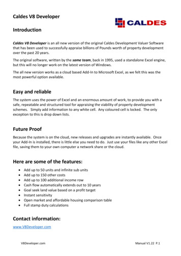
Standard Fencing Design CalculationsProject #: 161640.49Knotwood - FencingDesigned by: DSGChecked by: JSUDate: 03/26/2020Figure 1 - Typical 4x4 Fencing Plan View (2.5X2.5 Fence Similar)Figure 2 - Typical 4x4 Fencing Elevation View (2.5x2.5 Fence Similar)Knotwood FencingPage 12Prepared by PVE, LLC
Standard Fencing Design CalculationsProject #: 161640.49Knotwood - FencingDesigned by: DSGChecked by: JSUDate: 03/26/2020Check 6" Slats (KES15016):d 72 in(Max span considered)l 6 in(Tributary width on Slat)Loading:DLTotal DLselfS15016 0.9 plfwWLTotal wWind l 14.6 plfMax forces considering slat "pinned"DL 0.6WL Load Case (Considering WL perpendicular to flat face, so dead load does not cause bending):0.6 wWLTotal d 2MDist ――――― 0.5 kip in80.6 wWLTotal d DLTotal dVDist ――――― ――― 29.0 lbf22Check Slat Bending:MDistfbS150 ―― 2.5 ksiSxS150 Fab6063T5 5.2 ksi OKCheck Slat Shear:AS150 2 147 mm 1.5 mm 0.7 in 2VDistfvS150 ―― 4.2 10 -2 ksiAS150 FavS150 4.0 ksi OKTherefore, use of KES15016 is AcceptableKnotwood FencingPage 13Prepared by PVE, LLC
Standard Fencing Design CalculationsProject #: 161640.49Knotwood - FencingDesigned by: DSGChecked by: JSUDate: 03/26/2020Check Slat Fasteners:Allowable Connection Shear:The allowable connection shear is determined according to Section J.5.6, which specifies a safety factor Ω 3.0for fastener connection shear for building-type structures.Ω 3.0(ASD building-type structures)D 0.19 in(#10 Fastener Diameter)t1 0.059 in(Slat Thickness)t2 0.079 in(Slat Support Thickness)Section J.5.6.1 addresses bearing. Since the edge distance is 0.5 in. 0.38 in. 2(0.19in.) 2D, the allowablebearing force is 2FtuDt/W. Using Ftu from Table A.3.4, the allowable shear for bearing is:Ftu 22 ksi(Table A.3.4)2 Ftu D t1Fbearing ―――― 164.4 lbfΩVDist 15 lbf――2 OKFastener Pull Over:For t2 t1, Pull Over is not a limit state.Fastener Shear:Fvu 1.15 kip(#10 Ultimate Shear)FvuFshear ―― 383.3 lbfΩ VDist 15 lbf――2 OKFastener Tension:Nominal Pullout (ADM J.5.5, 0.060in Le 0.125 in)Ks 1.01ADM J.5.5.1.1D 0.2 inNominal diameter of screwFty2 30 ksiTensile yield strength of member not in contact with screw headLe t2 7.9 10 -2 inScrew engaged lengthRn Ks D Le Fty2 454.8 lbf(#10 Ultimate Pullout - ADM J.5-1)RnFpullout ― 151.6 lbfΩVDist ―― 15 lbf2 OKTherefore, use of #10 Screw is acceptableKnotwood FencingPage 14Prepared by PVE, LLC
Standard Fencing Design CalculationsProject #: 161640.49Knotwood - FencingDesigned by: DSGChecked by: JSUDate: 03/26/2020Check 4x4 6' High Posts (6' Max Spacing):d 6 ftl 6 ft(Max height of post)Tributary width on post12 DLselfS15016 lDLTotal ――――― DLself100100 2 DLself1W6525 14.8 plfdTotal dead load on postwWLTotal wWind l 174.6 plfMax forces considering post cantilevered.DL 0.6WL Load Case (Considering WL perpendicular to flat face, so dead load does not cause bending):0.6 wWLTotal d 2MDist2 ――――― 1.9 kip ft2VDist2 0.6 wWLTotal d DLTotal d 717.2 lbfCheck Post Bending:Sy100100 2.2 in 3Section Modulus for 4x4 Posts (KESG100100)MDist2Fcr4x4 ――― 10.2 ksiSy100100 Fab6061 19.5 ksi OK4x4 Post MaximumCheck Post Shear:AP4x4 2 3.58 in 0.118 in 0.8 in 2VDist2Fvpost ―― 0.8 ksiAP4x4Knotwood Fencing(Web Area) Fav4x4 13.1 ksiPage 15 OKPrepared by PVE, LLC
Standard Fencing Design CalculationsProject #: 161640.49Knotwood - FencingDesigned by: DSGChecked by: JSUDate: 03/26/2020Check 2-1/2x2-1/2 4' High Posts (Max 6' Spacing) :d 4 ftl 6 ft(Max height of post)Tributary width on post8 DLselfS15016 lDLTotal ――――― DLself2W6565 13.1 plfdTotal dead load on postwWLTotal wWind l 174.6 plfMax forces considering post cantileveredDL 0.6WL Load Case (Considering WL perpendicular to flat face, so dead load does not cause bending):0.6 wWLTotal d 2MDist3 ――――― 0.8 kip ft2VDist3 0.6 wWLTotal d DLTotal d 471.4 lbfCheck Post Bending:MDist3Fcr65x65 ――― 13.4 ksiSy2W6565 Fab6063 15.2 ksi OK2-1/2x2-1/2 Post MaximumCheck Post Shear:AP6565 2.5 in 0.118 in 0.3 in 2VDist3Fvpost ―― 1.6 ksiAP6565Knotwood Fencing(Web Area) Fav2.5x2.5 15.8 ksiPage 16 OKPrepared by PVE, LLC
Standard Fencing Design CalculationsProject #: 161640.49Knotwood - FencingDesigned by: DSGChecked by: JSUDate: 03/26/2020Check 2-1/2x2-1/2 5' High Posts (Max 4' Spacing) :d 5 ftl 4 ft(Max height of post)Tributary width on post10 DLselfS15016 lDLTotal ――――― DLself2W6565 9.3 plfdTotal dead load on postwWLTotal wWind l 116.4 plfMax forces considering post cantileveredDL 0.6WL Load Case (Considering WL perpendicular to flat face, so dead load does not cause bending):0.6 wWLTotal d 2MDist4 ――――― 0.9 kip ft2VDist4 0.6 wWLTotal d DLTotal d 395.7 lbfCheck Post Bending:MDist4Fcr65x65 ――― 14.0 ksiSy2W6565 Fab6063 15.2 ksi OK2-1/2x2-1/2 Post MaximumCheck Post Shear:AP6565 2.5 in 0.118 in 0.3 in 2VDist4Fvpost ―― 1.3 ksiAP6565Knotwood Fencing(Web Area) Fav2.5x2.5 15.8 ksiPage 17 OKPrepared by PVE, LLC
Standard Fencing Design CalculationsProject #: 161640.49Knotwood - FencingDesigned by: DSGChecked by: JSUDate: 03/26/2020Check 2-1/2x2-1/2 6' High Posts (Max 3' Spacing) :d 6 ftl 3 ft(Max height of post)Tributary width on post12 DLselfS15016 lDLTotal ――――― DLself2W6565 7.4 plfdTotal dead load on postwWLTotal wWind l 87.3 plfMax forces considering post cantileveredDL 0.6WL Load Case (Considering WL perpendicular to flat face, so dead load does not cause bending):0.6 wWLTotal d 2MDist5 ――――― 0.9 kip ft2VDist5 0.6 wWLTotal d DLTotal d 358.7 lbfCheck Post Bending:MDist5Fcr65x65 ――― 15.1 ksiSy2W6565 Fab6063 15.2 ksi OK2-1/2x2-1/2 Post MaximumCheck Post Shear:AP6565 2.5 in 0.118 in 0.3 in 2VDist5Fvpost ―― 1.2 ksiAP6565Knotwood Fencing(Web Area) Fav2.5x2.5 15.8 ksiPage 18 OKPrepared by PVE, LLC
Standard Fencing Design CalculationsProject #: 161640.49Knotwood - FencingDesigned by: DSGChecked by: JSUDate: 03/26/2020APPENDIX 'A'(References)Knotwood FencingPage 19Prepared by PVE, LLC
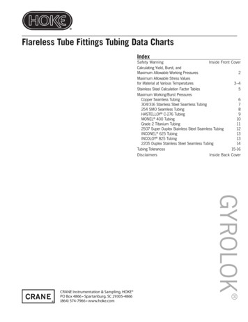
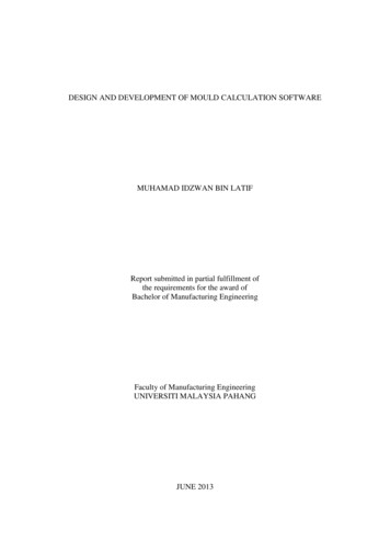
Standard Fencing Design CalculationsProject #: 161640.49Knotwood - FencingDesigned by: DSGChecked by: JSUDate: 03/26/2020Section 1616.2 from the 2017 Florida Building Code:Knotwood FencingPage 20Prepared by PVE, LLC
Standard Fencing Design CalculationsProject #: 161640.49Knotwood - FencingKnotwood FencingPage 21Designed by: DSGChecked by: JSUDate: 03/26/2020Prepared by PVE, LLC
Mar 26, 2020 · Knotwood Design Calculation: Methodology: When checking Knotwood Fencing (slats, posts, etc.), the applied wind loads, generated from ASCE 7-10 and the Florida Building Code Section 1616.2, are compared to allowable tension and shear s