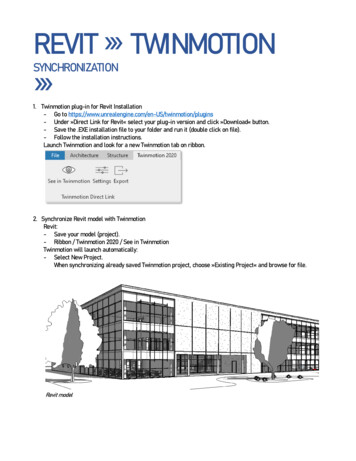
Transcription
Digital Built Week NA 2019BILT NAHyatt Regency Seattle18 – 20 July,2019Session 3.4Understand Revit’s Project Base Point andCoordinate SystemNicolas Catellier, Revit Pure / Atelier 21 Architectsrevitpure.com / nick@revitpure.comClass DescriptionThe coordinate system inside Revit seems to be insanely complicated. Did you ever try toexport a Revit file to specific coordinates and miserably fail? Did you know there was a secretinternal origin that is used by default when exporting a Revit file?This class will start from the very basic definition of the origin points. You will learn how tointegrate the points in your Revit template. You will learn to spot and identify them. You willlearn how to use the elevation height value in relation to the base points. You will learn how toset up the true north value.Then, you will learn how to link, import and export files in relation to the major points. We willthen jump to the complex topic of shared sites and shared coordinates. You will learn the bestworkflow to properly link files together when using a real-world survey data. Finally, you willlearn how to properly use the WGS84 lat-long coordinates and how to integrate all coordinatesinformation in your BIM execution plan.Class Objectives1. Learn the difference between all 3 coordinate origin points in Revit.2. Organize the use of base points, coordinates and true north in your master Revit template.3. Manage the coordinates when importing, exporting or linking external files.4. Use a shared site to host multiple buildings.About the Speaker:
3.4 Understand Revit’s Project Base Point and Coordinate SystemNicolas CatellierRevit PureNicolas Catellier is an Architect, BIM Manager and teacher based in Quebec City, Canada.Nicolas graduated from Université de Montréal in 2011 and has been working andexperimenting with BIM ever since. He started the learning website revitpure.com in 2016. Thesite provides content to help both beginners and advanced users learn Revit in a spirit of funand simplicity.Nicolas also works for Atelier 21 architects, where he engineered the transition from AutoCADto BIM for the entire office. He also completed projects such as the Valcartier, a 153 rooms hoteland a 70 000 square feet indoor waterpark. Nicolas acted as the lead BIM manager but also asa designer and rendering artist for the project. Bridging the gap between the technical aspect ofBIM and the creative process of architecture has always been a major goal for Nicolas.Page 2 of 37
3.4 Understand Revit’s Project Base Point and Coordinate SystemNicolas CatellierRevit PureUNDERSTAND THE DIFFERENCE BETWEEN ALL 3 COORDINATEORIGIN POINTSThere is 3 different origin points in a Revit project: the Project Base Point, the Survey Pointand the super secret Internal Origin.PROJECT BASE POINTThis point is used almost exclusively for internal purpose. It is used to spotcoordinates relatively to the building. It is represented by a blue circle with across in the middle. It can also be used to set the angle difference betweenthe True North and the Project North.Page 3 of 37
3.4 Understand Revit’s Project Base Point and Coordinate SystemNicolas CatellierRevit PureSURVEY POINTThis point is usually used to represent the origin of a “shared coordinates”system among multiple linked Revit or CAD files. That means its locationis most useful when exporting and importing files. It is usually placedrelatively to a real-world site element such as the intersection of 2property lines or a geodetic marker.INTERNAL ORIGINThis is the tricky one. This point is invisible and cannot be moved. Mostusers don’t even know it exists. By default, importing or exporting a CADor Revit file will be made relatively to this super secret point, thereforeconfusing many people.LOCATE THE INTERNAL ORIGINNow that you are aware of this super secret internal origin, you should locate it in a plan viewusing reference planes. Actually, you should locate it in your Revit Template so you will be ableto track its location for all new projects.To locate the point, go to your site plan and make sure the Project Base Point is set to visible inthe Visibility/Graphics settings.The next step is to select the project base point and click on the clip icon. A red dash shouldappear on the icon. The next step is to right-click on the project base point and select “Move toStartup Location”Page 4 of 37
3.4 Understand Revit’s Project Base Point and Coordinate SystemNicolas CatellierRevit PureThe project base point should now be located at the exact same spot as the Internal Origin.Mark this spot in the project by creating two reference planes that intersect at the point. Youshould also add a text note to indicate the location to other users. Make sure to pin thereference planes as well as the project base point.The 3 origin points not only have X/Y coordinates, but also a Z-axis elevation. Therefore, youshould open an elevation view and unhide the Project Base Point and Survey Point. Create athird reference plane to indicate the height location of the Internal Origin.Page 5 of 37
3.4 Understand Revit’s Project Base Point and Coordinate SystemNicolas CatellierRevit PureBY DEFAULT, KEEP THE BASE POINTS TOGETHERIn most small projects, the Project Base Point, the Survey Point and the Internal Origin canall remain in the same spot without any problem. In your template, make sure they all fittogether in a corner of your building, at the intersection of grids A and 1. Make sure to pin allthese points, reference planes and grids.Page 6 of 37
3.4 Understand Revit’s Project Base Point and Coordinate SystemNicolas CatellierRevit PureWhile the default stance is to keep these points together, the next tips will teach you in whichcase they should be moved.CREATE A SPOT COORDINATE FOR EACH ORIGINThe Spot Coordinate tool is used to specify coordinate relatively to one of the 3 origin. You canfind this tool in the Annotate tab.Page 7 of 37
3.4 Understand Revit’s Project Base Point and Coordinate SystemNicolas CatellierRevit PureIn your template, it is a smart move to create a Spot Coordinate for each of the 3 origin type.Edit the type of the spot coordinate and use the duplicate tool. Scroll down the settings optionsand will see the Coordinate Origin parameter. Create a different tag for all 3 origins (Survey,Project Base and Internal). Relative refers to the Internal Origin of the project.Page 8 of 37
3.4 Understand Revit’s Project Base Point and Coordinate SystemNicolas CatellierRevit PureOnce you are done, you should have 3 different Spot Coordinate types like in this image.As you can see in the image next page, each spot coordinate is used to spot the same element.However, they indicate different data since they each refer to a different origin. These tags canbe useful when you are confused about the location of the origin or of a specific element.TOPOSURFACE IS RELATIVE TO THE INTERNAL ORIGINThe 3 origins points each can have a different elevation value. When creating a toposurface,you have to set values referring to Absolute Elevation. This value is relative to the InternalOrigin.Page 9 of 37
3.4 Understand Revit’s Project Base Point and Coordinate SystemNicolas CatellierRevit PureSET PROJECT LEVELS ELEVATIONThere is a serious debate about what elevation the first level should be. That depends on yourgeographic location, local norms and office standards. The first option is to set the first level atelevation 10 000mm or 100’-0’’. The main reason is to avoid negative values for basementlevels, which can cause confusion on the construction site.Many people think this strategy is completely ridiculous and argue that level 1 should be set atelevation 0. In the end, both techniques are viable. Here is how to properly implement them.STRATEGY 1: SET LEVEL 1 AT ELEVATION 10 000mm (100’-0’’)Depending on your geographic location and local norms, you might need set the project firstlevel at 100’-0’’ or 10 000mm. This is an arbitrary value that has no relation to the sea level. Thebest practice is to set this value in relation to the Project Base Point. Select a level, click onEdit Type and make sure that the Elevation Base is set to Project Base Point.Page 10 of 37
3.4 Understand Revit’s Project Base Point and Coordinate SystemNicolas CatellierRevit PureSTRATEGY 2: SET LEVEL 1 AT ELEVATION 0mm (0’-0’’)USE INTERNAL ORIGIN AS SEA LEVEL 0In a project where you want to spot elements in relation to the sea level, you should use theInternal Origin to represent sea level 0.In this example, the 10 000mm project level fits the 4 835mm sea level. That means we have tomove the Project Base Point so it is 5 165mm below the Internal Origin base elevation.Creating a separate linked Revit model for the site might be a good idea, especially for largerprojects.If you want to spot any element in your project in relation to the sea level, create a new SpotElevation tag that use Relative as the Elevation Origin.Page 11 of 37
3.4 Understand Revit’s Project Base Point and Coordinate SystemNicolas CatellierRevit PurePlacing the Project Base Point relatively to the Internal Origin should be your first move whenstarting a project. Else, you won’t be able to model the site using the sea level elevation values.In a project where the site and project are already modelled without using the sea elevation, thesolution is to use the Survey Point as the sea level origin.Finally, it is often a good idea to create a separate linked Revit site model, especially in largerprojects. This way, you can modify the site independently from the building. The building heightposition can easily be adjusted. To learn more about linked site model workflow, see page 12.MOVING THE PROJECT BASE POINT AND SURVEY POINTBe extremely careful when moving the origin points. Both the Project Base Point and SurveyPoint have a clip icon next to them when selected. You need to fully understand what effect thisclip has on the points before actually moving them. Click on the clip icon to clip/unclip theProject Base Point or Survey Point.Page 12 of 37
3.4 Understand Revit’s Project Base Point and Coordinate SystemNicolas CatellierRevit PureAVOID MOVING CLIPPED PROJECT BASE POINTBe careful: moving a clipped Project Base Point will move the entire project (including theinternal origin) except the Survey Point. The effect is the same as moving a clipped SurveyPoint. Avoid this strategy unless you want to modify the building origin relative to the site.UNCLIP PROJECT BASE POINT BEFORE MOVING ITWhile you default stance should be to keep the Internal Origin and the Project Base Pointtogether, there are some good reasons to move the Project Base Point. First, unclip the ProjectBase Point. Move it to the proper emplacement, then clip it again. As you see, the coordinateswill be changed: the N/S and E/W coordinates are always relative to the Survey Point.Page 13 of 37
3.4 Understand Revit’s Project Base Point and Coordinate SystemNicolas CatellierRevit PureNEVER UNCLIP THE SURVEY POINTWhile unclipping the project base point is the standard procedure before moving it, you shouldnever unclip the Survey Point. If you unclip and move the Survey Point, you will cause a lot ofpain, horror and confusion for people working in your model.The only thing that moving an unclipped survey point will do is to move the icon representationof the survey point, not the survey point itself. If you click a survey point and you see somethingelse than 0,0,0 coordinates, that means someone messed up and decided to move anunclipped survey point. Simply change the values back to 0,0,0.Page 14 of 37
3.4 Understand Revit’s Project Base Point and Coordinate SystemNicolas CatellierRevit PureALTERNATE TAKE: IT’S OK TO MOVE AN UNCLIPPED SURVEY POINTWhile I stand by the idea that moving an unclipped a survey point is a terrible idea and shouldbe avoided, there is some people that think it is actually a good idea. When the site origin islocated 20 miles away from your project, the survey point triangle might be too far to be visible.Therefore, some BIM managers recommend to unclip the point and move it to a closer locationthat can be seen from your site plan. It can cause problems thought. More on that on page 28.USE PROJECT BASE POINT TO SET THE TRUE NORTHEach project contains a Project North and a True North. The Project North is a virtual orientationused to model your project so it is orthogonal to your screen. The True North is a real-worldnorth used to properly locate the orientation of your building. To set a True North value, selectthe Project Base Point and enter the angle.In the view properties of each view, you can specify the orientation you want to use. In almostall cases, Project North will be used.Page 15 of 37
3.4 Understand Revit’s Project Base Point and Coordinate SystemNicolas CatellierRevit PureBE CAREFUL: TRUE NORTH VALUE IS ACTUALLY EMBEDDED IN THE SURVEY POINTAlthough the True North value is set in the Project Base Point, the value is actually embedded inthe Survey Point. Even weirder: you can have multiple Survey Points in a project. That meansyou can have many multiple True North values in a single project. More on that later.EXPORTING TO CADMost users are confused about the project origin when exporting to CAD. The reason is that theInternal Origin is used by default. You can access the exportation options by going toFile/Export/CAD Format and by clicking the 3 small dots next to the Select Export Setup menu.Go to the Units & Coordinates tab.If you export a Revit view to DWG, the default setting is Project Internal. That setting will usethe Internal Origin as the 0,0,0 point location in AutoCAD.The other option is called Shared. This will use the Survey Point as the 0,0,0 point inAutoCAD.Page 16 of 37
3.4 Understand Revit’s Project Base Point and Coordinate SystemNicolas CatellierRevit PureWatch out: If you are using the Shared setting and you entered an angle value for the TrueNorth, the project will appear rotated once opened in AutoCAD. To avoid this issue, you canexport the sheet where the view is placed instead of exporting the view, although the sharedsite coordinates will be ignored.Page 17 of 37
3.4 Understand Revit’s Project Base Point and Coordinate SystemNicolas CatellierRevit PureHOW TO IMPORT / LINK CADThe Link CAD tool has more positioning options available than Import CAD. If you want to usethe Survey Point as the origin for the CAD file, you have to use Link CAD and select ByShared Coordinates. Else, the Origin to Origin option will match the Revit file Internal Originto the DWG 0,0,0 point.HOW TO LINK REVIT FILESRevit offers a fancy “Shared Site” and “Shared Coordinates” system to link Revit files. In mostcases, the Origin to Origin tool works perfectly fine. This option will match the models InternalOrigins. It is the best option when linking multiple disciplines together.Page 18 of 37
3.4 Understand Revit’s Project Base Point and Coordinate SystemNicolas CatellierRevit PureWhen linking a model, it is a wise move to PIN it immediately. If it moves around by mistake,right-click the model and use the “Reposition to Internal Origin” tool.USING SHARED SITESA shared site basically means a Survey Point that is shared among multiple models. Why wouldyou use this “shared site” feature? In a case where you want the survey points and thecoordinates to be the same on multiple models. In the example below, we have 4 Revit models:a site model, a big house model as well as 2 instances of a smaller house model.In this case, we want all the houses model to acquire the coordinates from the site model. First,link one of these models inside the site model. You can pick the Shared Coordinates option ifyou want, but since the models are not coordinated yet, you will receive a warning and thecenter to center option will be used anyway.Page 19 of 37
3.4 Understand Revit’s Project Base Point and Coordinate SystemNicolas CatellierRevit PureBelow is the warning you receive by default. This Shared Coordinates positioning option isbasically useless because you can assign the shared coordinates with any other positioningoption later anyway.Find the proper position you want for your linked building model inside the site model. Pin yourmodel. Once it is done, select the linked model and click “Shared Site” in the properties.When clicking Shared Site, here are all the options available to you:Page 20 of 37
3.4 Understand Revit’s Project Base Point and Coordinate SystemNicolas CatellierRevit PureIn this case, you should pick the first option: you want to publish the coordinates from the Sitemodel to the House model. Basically, this will move the survey point in the House model to be inthe same position as the site model. The operation will only be complete once you close the Sitemodel: you will be asked what to do with the linked house model position. Select the first option,which will update the survey point in the model.Try opening the house model: the survey point position will be updated to fit the same positionas in the site model. That means you can use the spot elevation and spot coordinates tool (withthe survey point option) that will match the linked site model.Page 21 of 37
3.4 Understand Revit’s Project Base Point and Coordinate SystemNicolas CatellierRevit PureCREATE MULTIPLE SHARED SITES IN A MODELLet’s say you are prefab house manufacturer and you want to reuse the same house Revitmodel on multiple sites. Revit gives you the ability to use multiple Shared Sites within the samemodel. When publishing coordinates from the site plan to the house model, click duplicate tocreate a second site.Save and close the site model, then open the pre-fab house file. Find the Survey Point anddouble click on the blue text “Survey Point - Internal”. Select the site you currently wish to useand click “Make Current”. The survey point location in the file will move to the correctcoordinates.Page 22 of 37
3.4 Understand Revit’s Project Base Point and Coordinate SystemNicolas CatellierRevit PureIn the end, you could have a pre-fab house model with 200 associated sites that you canactivate whenever you want. In the example below, we have multiple address. The survey pointindicates the current active one.ROTATING A LINKED BUILDING MODEL IN A SITE MODELLet’s say you are using the same pre-fab house multiple times on the same site. You rotate oneof the instances of the house and publish the new coordinates into a shared site. When youopen the house model, the true north will be modified to match the rotation you’ve used in thesite model.Page 23 of 37
3.4 Understand Revit’s Project Base Point and Coordinate SystemNicolas CatellierRevit PureIn the image above, the house is rotated in the site model. Publish the coordinate to a newShared Site. Close the site file and open the house model. Choose the correct Shared Site andopen a view set to True North. As you see, the project has the angle that match the rotationyou’ve used in the site model.Page 24 of 37
3.4 Understand Revit’s Project Base Point and Coordinate SystemNicolas CatellierRevit PureTHE DIFFERENCE BETWEEN SHARED SITE AND SHAREDCOORDINATESShared Coordinates and Shared Sites are not the same thing. In the examples provided in theprevious pages, we created multiple shared sites on a unified shared coordinate system. As youcan see in the image below, the survey point is always at the same spot for all models, but eachinstance of the building model has its own project base point and rotation value between truenorth and project north. Each instance of the building model has a unique shared site.ACQUIRING SHARED COORDINATES FROM A CAD FILEWhen creating a site in Revit, you might have to use a surveyor CAD file with a specific originlocation to be used by all disciplines. If that’s the case, make sure to link the CAD file insideRevit. The importation positioning options are not very important for the moment because wewill acquire coordinates anyway. The CAD origin is located at the corner of the property lines,while the default Revit origins are all at the same spot.Page 25 of 37
3.4 Understand Revit’s Project Base Point and Coordinate SystemNicolas CatellierRevit PureThe next step is to use the Acquire Coordinate tool located in the Manage tab. Then, click onthe CAD link.Page 26 of 37
3.4 Understand Revit’s Project Base Point and Coordinate SystemNicolas CatellierRevit PureThe Survey Point of the Revit file will automatically be moved to the CAD origin.As you can see, the Survey Point (shared site) is moved to the CAD origin. However, the RevitInternal Origin and the Project Base Point remain in their original location.If you select the CAD file, you will notice that the Shared Site instance parameter will display theshared site name. If you move a clipped survey point, the CAD file will also follow.Page 27 of 37
3.4 Understand Revit’s Project Base Point and Coordinate SystemNicolas CatellierRevit PureSURVEY POINT NOT THE SAME AS THE SHARED SITE?What if the CAD survey file origin point is super far from everything? Like 200 miles away?Some BIM expert think that you should unclip the Survey Point and manually move it to areasonable origin, like the corner of the property lines. Check out the image next page.In the image above, the Survey Point (unclipped blue triangle) and Shared Site (CAD origin) areused differently. I personally do not recommend this strategy as it is very risky and confusing.When using the Survey Point spot coordinate feature, the coordinates will refer to the 0,0,0origin of the survey point (shared site), not the unclipped blue triangle. The distinction betweenSurvey Point and Shared Site can get messy. Unclipping the survey point is just not a goodidea, unless your civil engineer specifically asks for it.Page 28 of 37
3.4 Understand Revit’s Project Base Point and Coordinate SystemNicolas CatellierRevit PureCREATE A MODEL WITH MULTIPLE TRUE NORTHSAs mentioned earlier, the true north value is changed in the Project Base Point but is embeddedin the Survey Point. That means you can have many true norths for the same project. This canbe useful if you want to create renderings using a certain north for lighting that is different fromthe real world north.In this case, create a second site in your survey point menu. Change the true north value in theProject Base Point. As you can see below, each site has its own angle from Project North toTrue North. When creating renderings, activate “RENDERINGS” site. When printing the plans toPDF, use the “REAL NORTH” site.Page 29 of 37
Digital Built Week NA 2019BILT NAHyatt Regency Seattle18 – 20 July,20196 STEPS TO CREATE SHARED COORDINATES FOR MULTIPLEREVIT MODELSIf you are working on a project where real-world coordinates are important, you will need aproper workflow to avoid problems. On the example below, we have a project containing modelsfor architecture, MEP and structure. The Survey Data from your civil engineer might or might notbe available when you start your project. It doesn’t matter. You can add the site model and thesurvey data at any moment in the project, when it is ready. The first step is always to create anarchitecture model.
Digital Built Week NA 2019BILT NAHyatt Regency Seattle18 – 20 July,20191- CREATE ARCHITECTURE MODEL, LOCATE IMPORTANT GRIDSINTERSECTION AT INTERNAL ORIGINThe first step is to create the main architecture model. Orient the views for convenience andignore the true north for the moment. Don’t model the site. That will be done later.The most important step is to place the building in relation to the internal origin. Usually, thatmeans at the corner of your building, where two major grids might intersect. Don’t mess up thisstep. You cannot relocate the internal origin of the project.2- LINK REVIT MODELS FROM ALL DISCIPLINES USING “ORIGINTO ORIGIN”If you have MEP and Structure models ready, you can link all the Revit files together. Use theAuto – Origin to Origin option. Always use this option and you will never have positioningproblems when linking multiple disciplines. Don’t worry about shared coordinates for now.
3.4 Understand Revit’s Project Base Point and Coordinate SystemNicolas CatellierRevit Pure3- CREATE SITE MODEL, LINK CAD SURVEY DATA, ACQUIRECOORDINATESOnce you have the Survey Data from your civil engineer or surveyor in hand, create a new Revitsite model. Make sure the internal origin in the CAD file containing the survey data is where itneeds to be. Then, use Link CAD to insert the file. The positioning option doesn’t really matter.Just make sure the CAD file isn’t too far from the Revit model internal origin. Use the AcquireCoordinates feature like you’ve learned in page 25. The Survey Point position should nowmatch the CAD survey origin.You can now start modeling a toposurface. Remember that all elevation values entered arerelative to the Revit Internal Origin.4- POSITION ARCHITECTURE MODEL ON THE SITE, PUBLISHCOORDINATESIn your Revit site model, link the architecture model using any positioning parameter. Manuallyposition the model, both in plan view and in elevation to match the topography. When you aredone, publish the coordinates from the Site Model to the Architecture Model (see page 20).Both models now share the same coordinate system. You can close the site model.When linking the site model inside the architecture model, make sure to use the “Auto – ByShared Coordinates” option. The survey point from the arch model should match the surveypoint from the site model.Page 32 of 37
3.4 Understand Revit’s Project Base Point and Coordinate SystemNicolas CatellierRevit Pure5- STRUCTURE AND MEP MODELS ACQUIRE COORDINATESFROM ARCHITECTURE MODELNow, time to propagate the shared coordinates to the Structure and MEP Models. TheArchitecture model should already be linked in the other disciplines’ files. Make sure to get thelatest arch model that includes the shared coordinates. Then, acquire the coordinates from thearchitecture model. Don’t use the Acquire Coordinates tool from the manage tab. Instead, clickon the Arch Revit link. In the instance properties, click on Not Shared in the Shared Siteinstance parameter. Select the “Acquire Coordinates” option. The survey point in the MEP andStructure file should be updated.6- LINK SITE MODEL INTO STRUCTURE AND MEP MODELS USING“BY SHARED COORDINATES”All the Revit files now share the same coordinate system. That means if you use the SpotCoordinate – Survey Point annotation tool you will get the exact same result on any model. Italso allows you to spot elevation values referring to the sea level. Link the site inside thestructure and MEP models if required. Make sure to use the Auto – By Shared Coordinatespositioning tool.Page 33 of 37
3.4 Understand Revit’s Project Base Point and Coordinate SystemNicolas CatellierRevit PureOn a site containing multiple projects, the chart might look like this:Page 34 of 37
3.4 Understand Revit’s Project Base Point and Coordinate SystemNicolas CatellierRevit PureWORKING WITH WGS84 (LATITUDE-LONGITUDE) COORDINATESThe Revit 2018 update allows you to use real world coordinates. Select the survey point andlook at the instance properties. You will see properties for latitude and longitude.However, you can’t manually fill up the information. You must acquire the coordinates from alinked CAD file that uses real world WGS84 coordinates. In the image, you link a surveyor CADfile that has been geolocated and acquire the coordinates. If you select the Survey Point, youcan see the geolocation data has been updated.Another thing to notice: the survey point didn’t move. That is because the site extents are so big(470 km x 2 147km) that the survey point can’t manage to get to the origin. Be careful with hugesites.Page 35 of 37
3.4 Understand Revit’s Project Base Point and Coordinate SystemNicolas CatellierRevit PureINTEGRATING COORDINATES INFORMATION IN A BIMEXECUTION PLANWhen writing a BIM execution plan, you should list all the important coordinate points andinclude a screen shot. Make sure to list the internal origin, the project base point and the surveypoint of the linked site model (if applicable). Make sure to also indicate the elevation values. Itshould look like this:PROJECT BASE POINT:The project base point of the architecture model is located at the intersection of grids A and 1.INTERNAL ORIGIN:The internal origin is also located of the grids A and 1, intersecting in height with level 1.Page 36 of 37
3.4 Understand Revit’s Project Base Point and Coordinate SystemNicolas CatellierRevit PureSURVEY POINT:The survey point of the linked Revit site model is located at the south-west property lineintersection. The elevation at height 0 refers to the sea level.After setting up these coordinate points, they should be pinned and never moved again.FURTHER READINGS:Steve Stafford’s Revit Op-Ed blog has a lot of posts about coordinates. Check it out coordinate-post-summary.htmlPaul Aubin Revit Coordinates guide:http://paulaubin.com/ downloads/2015 RTC/Aubin Revit Coordinates 2016.pdfRevit Pure original blog post about Page 37 of 37
3.4 Understand Revit’s Project Base Point and Coordinate System Nicolas Catellier Revit Pure Page 2 of 37 Nicolas Catellier is an Architect, BIM Manager and teacher based in Quebec City, Canada. Nicolas graduated fro