Transcription
Basics of BuswayA quickSTEP Online Course Siemens industry, Inc.www.usa.siemens.com/step
TrademarksSiemens is a trademark of Siemens AG. Product names mentioned may be trademarks or registeredtrademarks of their respective companies.National Electrical Code and NEC and NFPA 70 are registered trademarks of the National FireProtection Association.NEMA is a registered trademark and service mark of the National Electrical Manufacturers Association.UL is a registered trademark of UL, LLC.Other trademarks are the property of their respective owners. Siemens Industry, Inc. 2016Page 1-2
Course TopicsWelcome to Busway. This course covers thefollowing topics:Chapter 1 - Introduction Overview Circuit ProtectionChapter 2 – Sentron Busway Overview Components Bus PlugsChapter 3 – System Design Planning a SystemChapter 4 – XJ-L HD, XL-U, and BD Busway XJ-L HD Busway XL-U Busway BD BuswayFinal ExamIf you do not have an understanding of basicelectrical concepts, you should complete Basicsof Electricity before attempting this course. Siemens Industry, Inc. 2016Page 1-3
Course Objectives Upon completion of this course you will be able to Describe the role of busway in an electrical distribution system.Define common terms used to describe busway systems.Describe the cost-saving benefits of using busway rather than cable andconduit.Describe key features and advantages of Siemens Sentron busway.Describe the functions of various busway components.Describe the steps involved in planning a busway layout.Describe the key features of Siemens XJ-L HD, XL-U, and BD busway. Siemens Industry, Inc. 2016Page 1-4
SITRAIN Training for IndustryOnline Self-paced Learning – Programs with maximum flexibility so students can easily fitcourses into their busy schedulesVirtual Instructor-led Learning - Classroom lectures delivered in the convenience of yourhome or officeClassroom Learning - Expert and professional instructors, proven courseware, and qualityworkstations combine for the most effective classroom experience possible at your facility oroursHow-to Video Library - Quick, affordable, task-based learning options for a broad range ofautomation topics for training or purchaseSimulators - World-class simulation systems available for training or purchaseThis course also describes learning options available from the Siemens SITRAIN USA organization and ourglobal SITRAIN partners. For additional information: www.usa.siemens.com/sitrain Siemens Industry, Inc. 2016Page 1-5
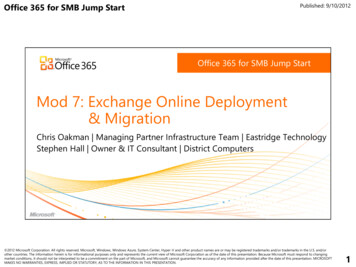
Power Distribution SystemsEvery residential, commercial, and industrial building has atleast one power distribution system that distributes power.Distribution systems used in commercial and industriallocations are complex. As shown in the accompanyinggraphic, a commercial or industrial power distributionsystem can include switchgear, switchboards, transformers,and panelboards.In many cases, especially in smaller facilities, power isdistributed to these various components using only cablescontained in conduit and/or cable trays. Busway is analternative approach for distributing power and is the focusof this course.Good distribution systems don’t just happen. Carefulengineering is required to ensure the distribution systemsafely and efficiently supplies adequate electric service toboth present and possible future loads. Siemens Industry, Inc. 2016Page 1-6
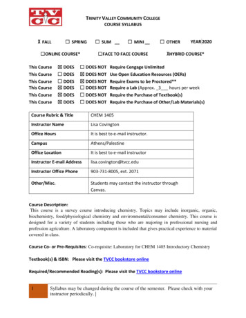
Commercial and Industrial Power SystemsUnlike single-family residential applications, which in mostcases use only single phase power, commercial andindustrial applications primarily use three-phase power.Transformers used with three-phase power require threeinterconnected coils in both the primary and the secondary.These transformers can be connected in either a wye or adelta configuration. The type of transformer and the voltagedepend on the requirements of the power company and theneeds of the customer.The accompanying illustration shows the secondarywindings of a wye-connected transformer and thesecondary windings of a delta-connected transformer. Forsimplicity, the primary windings are not shown.These are only examples of possible distributionconfigurations, the specific voltages and configurations varywidely depending upon the application requirements. Siemens Industry, Inc. 2016Page 1-7
FeedersA feeder is a set of conductors that originate at a maindistribution center and supply one or more secondary orone or more branch circuit distribution centers.Three feeders are shown in the accompanying graphic. Thefirst feeder is used for various types of power equipment.The second feeder supplies a group of 480 VAC motors.The third feeder is used for 120VAC lighting andreceptacles. Siemens Industry, Inc. 2016Page 1-8
Busway Bus BarsCommercial and industrial distribution systems use severalmethods to transport electrical energy. These methods mayinclude heavy conductors run in trays or conduit.Cable and conduit assemblies are costly and timeconsuming to install. Once installed, they are difficult tochange. To eliminate these shortcomings, power is oftendistributed using bus bars in an enclosure. This is referredto as busway.A bus bar is a conductor that serves as a commonconnection for two or more circuits. Bus bars are used in avariety of power distribution components, including busway.Bus bars in Siemens busway are made of aluminum orcopper. Siemens Industry, Inc. 2016Page 1-9
NEMA DefinitionBusway is defined by the National Electrical ManufacturersAssociation (NEMA) as: a prefabricated electrical distribution system consisting ofbus bars in a protective enclosure, including straightlengths, fittings, devices, and accessories.Siemens offers busway systems with the capabilities andoptions needed for a wide range of applications. Siemens Industry, Inc. 2016Page 1-10
Busway AdvantageA major advantage of busway is the ease with whichbusway sections are connected. Electrical power can besupplied to any area of a building by connecting quicklyconnecting busway sections.Because busway takes many fewer labor hours to installthan comparable cable and conduit assemblies, buswaycosts between 15% to 40% less to install, depending uponamperage. Siemens Industry, Inc. 2016Page 1-11
Busway ApplicationsBusway is used in a wide variety ofapplications, including complex industrialplants, data centers, offices, continuousprocess/ manufacturing facilities, high-risebuildings and many more. There are twomajor types of busway installations:horizontal and vertical.Horizontal busway is often used inindustrial and data center applications tosupply power to heavy equipment, lighting,and HVAC systems.Vertical busway, busway risers, can beinstalled economically in high-rise buildingswhere it is used to distribute power tolighting, building systems, office equipment,and HVAC loads. Siemens Industry, Inc. 2016Page 1-12
Siemens Busway Product PortfolioSiemens manufactures Sentron busway and the other types of busway shown above. Throughout this course, SiemensSentron busway examples are used to explain and illustrate busway principles and features. An overview of XJ-L HD,XL-U, and BD busway is provided later in this course. Siemens Industry, Inc. 2016Page 1-13
Feeder and Plug-in BuswayThere are two general types of busway:feeder and plug-in. Feeder busway is usedto distribute power to loads that areconcentrated in one physical area.Industrial applications frequently involvelong runs from the power source to a singleload. This load may be a large machine,motor control center, panelboard, orswitchboard.Plug-in busway is used when powerrequirements are distributed over a largearea. The use of bus plugs allows loadconnections to be easily added orrelocated. Siemens Industry, Inc. 2016Page 1-14
Service EntranceThe service entrance is the point of entry for powerconductors to a building. Feeder busway, which can betotally enclosed for outdoor use, can be used to distributepower from a utility transformer to a main disconnect insidethe building. Be careful to ensure that minimum clearancesare observed between busway joints and the wallpenetration. Siemens Industry, Inc. 2016Page 1-15
StandardsUL 857NEMA BU1CSA C22.2IEC 60429 (2004)BS EN 60529BS EN 60439-1, 60439-2UL 1479DIN 4102 Parts 9 & 12Multiple standards define busway design, construction,installation, and performance. For example, Sentronbusway meets the standards shown in the accompanyinglist. BS standards are issued by British Standards Institution(BSI). CSA standards are issued by the CSA Group (formerlythe Canadian Standards Association; CSA). DIN standards are issued by Deutsches Institut fürNormung e.V. (German Institute for Standardization). IEC standards are issued by the InternationalElectrotechnical Commission. NEMA standards are issued by the National ElectricalManufacturers Association. UL standards are issued by UL, LLC. (formerlyUnderwriters Laboratories).BS 6387 Parts 11.1 and 11.2 Siemens Industry, Inc. 2016Page 1-16
National Electrical Code The National Electrical Code (NEC ), also known asNFPA 70 , is issued by the National Fire ProtectionAssociation (NFPA). An updated version of the NEC isissued every three years. Article 368 of the NEC specifically applies to busway. Other articles also haveapplicable information.State and local electrical codes are often based on aversion of the NEC, but can also provide additionalrequirements.In addition, busway used at a service entrance may beconnected to a distribution transformer owned by an electricpower company, which may also have its ownrequirements. Siemens Industry, Inc. 2016Page 1-17
Chapter 1 – IntroductionThis chapter covers the followingtopics: Overview Circuit Protection Siemens Industry, Inc. 2016Page 1-18
OvercurrentCurrent flow in a conductor always generates heat. Thegreater the current flow, the hotter the conductor. Excessheat is damaging to electrical conductors. For that reason,conductors have a rated continuous current carryingcapacity or ampacity. Current beyond the rated ampacity ofa conductor is referred to as overcurrent. Overcurrent canresult from a short circuit, an overload, or a ground fault.The first two types of overcurrent conditions are describedin the following paragraphs.A short circuit occurs when two bare conductors touchcausing the resistance between the conductors to dropsignificantly. This reduction in resistance causes animmediate and destructive increase in current.An overload is a typically a much lower current than a shortcircuit. An overload occurs when too many devices or thewrong type of devices are connected to a circuit or whenelectrical equipment is made to work beyond its ratedcapabilities. Siemens Industry, Inc. 2016Page 1-19
Short CircuitsWhen exposed conductors touch, a short circuit occurs, andthe circuit resistance drops to nearly zero. Because of thisvery low resistance, short circuit current can be thousandsof times higher than normal operating current.Ohm’s Law shows the relationship of current, voltage, andresistance. For example, a 240 volt motor with 24 ohms ofresistance would normally draw 10 amperes of current.When a short circuit occurs, resistance drops dramatically.For example, if the above resistance dropped to24 milliohms (0.024 ohms) due to a short circuit, the currentwould increase to 10,000 amps. Siemens Industry, Inc. 2016Page 1-20
Instantaneous Overcurrent ProtectionWhen a short circuit occurs in an unprotected circuit,current continues to flow until the circuit is damaged or thepower is removed manually.The peak short-circuit current of the first cycle is thegreatest and is referred to as peak let-through current (IP).The electromagnetic force associated with this current cancause mechanical damage to electrical components.The peak let-through energy (I2T) associated with thiscurrent can produce enough heat to melt conductors.A properly applied overcurrent protection deviceinstantaneously opens the circuit, limiting peak let-thrucurrent and peak let-thru energy. Siemens Industry, Inc. 2016Page 1-21
OverloadsIn general, the greater the amount of overcurrent, the morequickly a circuit must be disconnected from its powersource. Therefore, instantaneous overcurrent protection isessential when a short circuit occurs. Overloads, however,require a delayed response. To understand this better,consider the operation of a typical AC induction motor.When most motors start, they draw current in excess oftheir full-load current rating. For example, a NEMAdesign B motor typically has a starting current of about sixtimes its full-load current. For some high-efficiency motors,the starting current is even higher. Motors are designed totolerate a high starting current for a short time. As a motoraccelerates to operating speed, its current drops off quickly.In the accompanying example, the motor’s starting currentrises to 600% of full load current, but after eight seconds,current has dropped to the rated value. Depending on thesize of the motor, the time required for the current to drop tothe full load level or below may be shorter or longer.Whatever this time is, the motor’s power circuit must bedesigned to handle this short-duration overload. Siemens Industry, Inc. 2016Page 1-22
FusesMost fuses are one-shot devices. When a fault occurs, thefuse element melts and opens the path for current,interrupting the fault. The time it takes for a fuse to interruptthe fault is called the clearing time, which includes the timeit takes for the fuse element to melt plus the time it takes toextinguish the arc of current across the melting element.The clearing time for a fuse is inversely related to the levelof fault current over a fuse’s designed range. This meansthat the fuse clearing time is less for a higher level of faultcurrent than for a lower level of fault current.Many fuses used in power distribution systems are currentlimiting. There are various factors required to classify acircuit protection device as current limiting, but essentially itmeans that, as shown in the accompanying graphic, acurrent limiting fuse significantly reduces the peak let-thrucurrent when a fault occurs. The intent is prevent damageto conductors and protected equipment by reducing theelectrical energy applied to the conductors and load. Siemens Industry, Inc. 2016Page 1-23
Fuse TypesThere are various types of fuses used in power distributionsystems. Three common types are shown in theaccompanying list.Fast-Acting FuseTime-Delay FuseDual Element FuseFast-acting fuses open quickly when an overcurrent occurs.For this reason, they are used to provide short circuitprotection for non-inductive loads. As such, they are notsuitable for use with motors and other inductive loads.Time-delay fuses provide a delayed response to allowtemporary overloads to clear. Because the amount of delayrequired varies with the load characteristics, fuses areavailable to fit the full range of load requirements. Timedelay fuses provide both short circuit and overloadprotection and are used in a wide range of applications.Dual-element fuses may have time-delay designationbecause these fuses have two fuse elements. One elementprovides overload protection with a time delay. (UL statesthat time delay means having a 10-second operating delayat 500% of the fuse label rating.) The second elementprovides short circuit protection similar to a single-elementfuse. Dual-element fuses are most frequently used onmotor loads. Siemens Industry, Inc. 2016Page 1-24
Circuit Protection Device RatingsVoltage RatingAmpere RatingInterrupting RatingBecause application requirement vary, circuit protectiondevices (fuses and circuit breakers) are available with awide range of characteristics. In addition to size,mechanical design, and element type, the ratings shown inthe accompanying list must be considered when choosing acircuit protection device for an application.The voltage rating of a device must be at least equal to thecircuit voltage. The voltage rating of a device can be higherthan the circuit voltage, but never lower. A 600 volt device,for example, could be used in a 480 volt circuit, but a240 volt fuse should not be used in a 480 volt circuit.The ampere rating, also called the continuous currentrating, of a circuit protection device is its continuouscurrent-carrying capacity. The ampere rating of devicemust match the requirements of the load and associatedconductors.The interrupting rating of a circuit protection device is themaximum current that the device can safely interrupt. Theinterrupting rating required must be at least equal to thelevel of fault current available for the circuit. Siemens Industry, Inc. 2016Page 1-25
Low Voltage Fuse ClassesUL, LLC. (formerly Underwriters Laboratories)establishes and standardizes basic performanceand physical specifications for products thatundergo its safety test procedures. Among thestandards developed by UL are standards forclasses of low voltage fuses (fuses with voltageratings of 600 volts or less).Fuses are grouped into classes based on theiroperating and construction characteristics andratings. When selecting fuses, it is a good idea torefer to the fuse manufacturer’s application data tomake sure that a specific fuse is appropriate for thefault characteristics and types of loads involved.The accompanying graphic shows the mostcommonly used low voltage fuse classes withSiemens busway.The accompanying graphic also shows fuse kitsrequired for class R fuses. A class R fuse kitprevents the use of lower rated H and K fuses. Siemens Industry, Inc. 2016Page 1-26
Circuit BreakersAnother device used for overcurrent protection is a circuitbreaker. Although some circuit breakers do incorporatefuses, most do not, but, like a fusible switch, a circuitbreaker provides overcurrent protection and a manualmeans of controlling power distribution.When an overcurrent occurs, the circuit breaker trips toremove power from the circuit. The greater the overcurrent,the more rapidly the circuit breaker trips. Once theovercurrent condition has been corrected, a simple flip ofthe breaker’s operating handle restores the circuit.The ability to restore a circuit without replacing a fuse is oneof the key advantages of a circuit breaker. However, circuitbreakers have other advantages as well.For example, some circuit breakers have adjustments or areplaceable trip unit to allow the level of fault currentrequired to trip the breaker to be set to match theapplication.Some circuit breakers also have communication capabilityto allow information to be sent to power monitoringequipment or display devices. Siemens Industry, Inc. 2016Page 1-27
Circuit Breaker Frame SizeThe circuit breaker frame includes all the variouscomponents that make up a circuit breaker except for thetrip unit.For any given frame, circuit breakers with a range of currentratings can be manufactured by installing a different trip unitfor each rating.The breaker frame size is the highest continuous currentrating for a breaker with a given frame. Siemens Industry, Inc. 2016Page 1-28
Chapter 2 – Sentron BuswayThis chapter covers the followingtopics: Overview Components Bus Plugs Siemens Industry, Inc. 2016Page 2-1
Conductors and HousingThe following Sentron busway bus bar (conductor) types are available: 98% conductivity copper M-rated, 1000 A/in2 copper 58% conductivity aluminum L-rated, 750 A/in2 aluminumStandard conductors are electroplated with tin. Silver finishedconductors are optional. The conductors are insulated with a state-ofthe-art epoxy insulation system applied using an electrostatic sprayprocess for optimal insulation integrity. Sentron Busway insulation isClass B 130 C Rated. Every conductor and completed assembly isdielectric tested to ensure the insulation is free of defects.Sentron busway conductors are installed in a light-weight, allaluminum housing. The totally enclosed, non-ventilated housingresists rust and other elements, distributes heat away from theconductors, and provides an excellent ground path. The totallyenclosed design also eliminates the need for derating of the systemregardless of installation orientation.The housing is covered with an electrostatically-applied light grayANSI 61 polyester urethane powder paint that is scratch resistant andhas a 1,000-hour salt spray resistance rating. Siemens Industry, Inc. 2016Page 2-2
Conductor ConfigurationsSentron busway is available for the following powerconfigurations: 3-phase, 3-wire 3-phase, 4-wire, 100% neutral 3-phase, 4-wire with 200% neutralSentron busway with aluminum conductors is available withampere ratings up to 4000 amps. Sentron busway with copperconductors is available with ampere ratings up to 5000 amps.The accompanying graphic shows the standard NEMA phasearrangement for a 3-phase, 5-wire, 200% neutral configurationwith an internal ground.The optional 200% neutral is designed to handle additionalharmonics currents generated by some types of lighting andelectronic equipment. Siemens Industry, Inc. 2016The NEC requires the metal enclosure of a busway run to begrounded at the service entrance equipment. Sentron buswayincludes a standard integral aluminum housing ground (atleast 50% of phase current carrying capacity) and can includeoptional internal grounding bars (at least 100% of phasecurrent carrying capacity). An optional isolated ground is alsoavailable.Page 2-3
Busway SectionsSentron feeder busway sections are available incustom lengths from 2 to 10 feet.Sentron plug-in busway with plugs on both sidesand riser busway with plugs on one side (sometimesreferred to as one sided plug-in) are available in thefollowing lengths: 4, 6, 8, and 10 feet. Note that riserbus may be used in horizontal applications if plugins are only required on one side of the busway.Plug-in outlets are located on 2 feet centers on bothsides of the busway for plug-in busway and on oneside for riser busway. The plug-in outlet features amolded guard which prevents incidental fingercontact with live conductors. This meets IEC, IP 2Xrequirements for preventing a 0.472” probe fromentering. This is referred to as “finger safe”.nb3Outdoor feeder busway is available with aNEMA 3R enclosure for NEMA markets or an IP66ingress protection rating for IEC markets.Indoor feeder and plug-in busway are available withan IP40 or IP55 (splash proof) rating. Siemens Industry, Inc. 2016Page 2-4
Joint StackEach Sentron busway piece is shipped with a joint stackand joint covers installed at one end of the busway and ashipping end protector at the other end. Joint stacksfeature a single bolt design and a special, torque indicating,double-headed, break-off bolt. This eliminates the need fortorque wrenches and assures proper torque at installationof 50 ft.-lbs.(68 N-m).When the proper torque value is achieved, the top bolt headshears off. Each joint stack allows for /- 0.625 inchesadjustability at each joint. Over adjustment is prevented bythe joint covers, which will only allow a 0.625 inchadjustment when the knockouts on the joint cover areremoved.Link to Sentron Joint Assembly Instructional Video:https://www.youtube.com/watch?v PI8In1a0nmc Siemens Industry, Inc. 2016A joint connection assembly can be removed to allowelectrical isolation or removal of a busway lengthwithout disturbing adjacent busway lengths. Isolation jointstacks are available and used to electrically isolate abusway section within a busway run. For easy visualidentification, isolation joint stack assemblies are paintedwhite.Page 2-5
Chapter 2 – Sentron BuswayThis chapter covers the followingtopics: Overview Components Bus Plugs Siemens Industry, Inc. 2016Page 2-6
ElbowsElbows enable turns and height changes in thebusway system. An elbow can turn the buswaysystem right, left, up, or down.Elbows are supplied with a joint stack andcovers. Elbows may be ordered as stacks orsections. Elbow stacks are joint stacks that areangled edgewise (for up/down changes) orflatwise (for left/right changes).Combination elbows can route the buswaysystem up or down, and right or left. They areavailable in a variety of configurations. Siemens Industry, Inc. 2016Page 2-7
Tees, Crosses, and OffsetsTees are used to start a new section of busway in adifferent direction. Tees can start a new section to the right,to the left, up, or down. Tees are supplied with two jointstacks.A cross allows a busway run to extend in four directions.Offsets allow the busway system to shift left, right, up, ordown while continuing in the same direction. Offsets aresupplied with a joint stack. When space is tight, a singleoffset can be used instead of two connected elbows. Siemens Industry, Inc. 2016Page 2-8
Tap BoxesTap boxes are used to connect electrical cable to busway.End cable tap boxes can be installed at either end of thebusway system. They can be used on feeder or plug-inbusway.Center cable tap boxes are used to feed power to or takepower from the busway run at a point other than the start orend. Siemens Industry, Inc. 2016Page 2-9
Flanged EndsSentron busway standard flanged ends are used to connectbusway to other Siemens equipment, such as switchgear andswitchboards.Flanged ends can also be used with existing equipment. Siemenswill furnish the outline drawings of this flanged end to thecoordinating switchboard or equipment installer. Siemens Industry, Inc. 2016Page 2-10
Service HeadsService heads are used to connect the busway to the electricalservice. There are two types in the Sentron series. A singleservice head that has all three phases, or three separate heads,one for each phase. Siemens Industry, Inc. 2016Page 2-11
Riser Adaptors (or Tap Stacks)For vertical applications, Sentron plug-in busway can beordered with the plug-in receptacles located only on oneside. This is called “riser” busway.The phasing on vertical busway is A, B, C, N from left toright on the predominant side of the busway. This ensuresproper bus plug orientation.Some panelboards and meter centers, such as SiemensPower Mod, can be mounted directly to risers with a jointmounted adapter, sometimes referred to as a tap stack. Ameter center cubicle, with main breaker in the cubicle, mayalso be used to feed a meter center lineup. The circuitprotection in the cubicle means a main switch or breaker isnot required in the meter lineup. Siemens Industry, Inc. 2016Page 2-12
Bus Bar Phase RotationSome applications may require a phase rotation of the powersupply. The direction of rotation of a 3 phase AC motor, for example,is determined by the phase sequence of the power supply. Thesefittings are most common in transitions from horizontal to verticalruns, where specific phase sequences are required to properlyposition bus plugs.Phase rotation fittings are available as phase and ground, phaseonly, and ground only rotations. Note: phase rotation fittings aredifficult to manufacture and should be limited in use. Siemens Industry, Inc. 2016Page 2-13
ReducersA busway reducer is used to reduce the ampere rating fromone busway section to another, This allows a lower ratedbusway section to be connected further down a run. A branchcircuit, for example, does not need as high an ampere ratingas the main feeder circuit.The NEC requires overcurrent protection where busways arereduced in ampacity. There is an exception to this requirementfor industrial applications. Refer to the NEC for additionalinformation.Sentron busway offers reducers with fuse provisions. With theproper fuses installed, these reducers meet NEC overcurrentprotection requirements. Non-fused reducers are available forapplications in which the exception is allowed. Theaccompanying graphic shows a fused reducer. Siemens Industry, Inc. 2016Page 2-14
Expansion Fittings, Cubicles, and End ClosersExpansion fittings accommodate expansion and contraction of abusway run and building movement. The Sentron expansion fittingis configured with a sliding enclosure and flexible conductors thatallow up to 2 inches of movement.Expansion fittings are typically installed in the middle of longbusway runs, and at the beginning of certain riser runs.One expansion section should be used for every 200 feet ofcontinuous busway run length, at the beginnings of most verticalruns, and at each building expansion joint. The busway run mustbe positioned accordingly to accommodate the expansionsection(s).Cubicles provide a means of mounting switches or circuit breakerswhere power enters or leaves a busway system. In-linedisconnect cubicles are used where bolted connections arepreferred or at ampere ratings exceeding the standard plug-in unitratings. Modifications are available to accommodate keyinterlocks, ground fault detectors, and power monitors.End closers are used to safely terminate a run of busway andprotect the bus bar ends. They are easily removed to extend abusway run. Siemens Industry, Inc. 2016Page 2-15
Hangers and FlangesVarious hangers are used to support busway. When a verticalrun of busway passes through a floor, a floor support is required.Spring hangers provide secure mounting of Sentron busway inriser applications. These hangers counter the weight of thebusway on each floor and compensate for minimal buildingmovement and thermal expansion and contraction of the product.Several types of hangers are available to suspend the buswayfrom the ceiling or a structural steel support, or to mount buswayon a wall.Flanges are used when the busway run passes through a roof,wall or ceiling. It is important to note that flanges do not supportthe busway; rather they provide a means of covering the holethrough which the busway passes. Sealant, may be required tomeet fire codes or other local requirements. Sealant, caulking, orgaskets are not provided with Sentron flanges.Roof flanges provide a watertight seal when outdoor ratedbusway enters through a roof. The
National Electrical Code The National Electrical Code (NEC ), also known as NFPA 70 , is issued by the National Fire Protection Association (NFPA). An updated version of the NEC is issued every three years. Article 368 of the NEC specifically applies to busway. Other articles also have applicable inf