Transcription
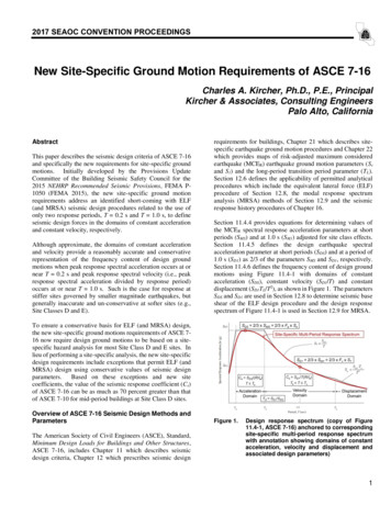
2017 SEAOC CONVENTION PROCEEDINGSNew Site-Specific Ground Motion Requirements of ASCE 7-16Charles A. Kircher, Ph.D., P.E., PrincipalKircher & Associates, Consulting EngineersPalo Alto, CaliforniaAbstractThis paper describes the seismic design criteria of ASCE 7-16and specifically the new requirements for site-specific groundmotions. Initially developed by the Provisions UpdateCommittee of the Building Seismic Safety Council for the2015 NEHRP Recommended Seismic Provisions, FEMA P1050 (FEMA 2015), the new site-specific ground motionrequirements address an identified short-coming with ELF(and MRSA) seismic design procedures related to the use ofonly two response periods, T 0.2 s and T 1.0 s, to defineseismic design forces in the domains of constant accelerationand constant velocity, respectively.Although approximate, the domains of constant accelerationand velocity provide a reasonably accurate and conservativerepresentation of the frequency content of design groundmotions when peak response spectral acceleration occurs at ornear T 0.2 s and peak response spectral velocity (i.e., peakresponse spectral acceleration divided by response period)occurs at or near T 1.0 s. Such is the case for response atstiffer sites governed by smaller magnitude earthquakes, butgenerally inaccurate and un-conservative at softer sites (e.g.,Site Classes D and E).requirements for buildings, Chapter 21 which describes sitespecific earthquake ground motion procedures and Chapter 22which provides maps of risk-adjusted maximum consideredearthquake (MCER) earthquake ground motion parameters (Ssand S1) and the long-period transition period parameter (TL).Section 12.6 defines the applicability of permitted analyticalprocedures which include the equivalent lateral force (ELF)procedure of Section 12.8, the modal response spectrumanalysis (MRSA) methods of Section 12.9 and the seismicresponse history procedures of Chapter 16.Section 11.4.4 provides equations for determining values ofthe MCER spectral response acceleration parameters at shortperiods (SMS) and at 1.0 s (SM1) adjusted for site class effects.Section 11.4.5 defines the design earthquake spectralacceleration parameter at short periods (SDS) and at a period of1.0 s (SD1) as 2/3 of the parameters SMS and SD1, respectively.Section 11.4.6 defines the frequency content of design groundmotions using Figure 11.4-1 with domains of constantacceleration (SDS), constant velocity (SD1/T) and constantdisplacement (SD1TL/T2), as shown in Figure 1. The parametersSDS and SD1 are used in Section 12.8 to determine seismic baseshear of the ELF design procedure and the design responsespectrum of Figure 11.4-1 is used in Section 12.9 for MRSA.To ensure a conservative basis for ELF (and MRSA) design,the new site-specific ground motions requirements of ASCE 716 now require design ground motions to be based on a sitespecific hazard analysis for most Site Class D and E sites. Inlieu of performing a site-specific analysis, the new site-specificdesign requirements include exceptions that permit ELF (andMRSA) design using conservative values of seismic designparameters. Based on these exceptions and new sitecoefficients, the value of the seismic response coefficient (Cs)of ASCE 7-16 can be as much as 70 percent greater than thatof ASCE 7-10 for mid-period buildings at Site Class D sites.Overview of ASCE 7-16 Seismic Design Methods andParametersThe American Society of Civil Engineers (ASCE), Standard,Minimum Design Loads for Buildings and Other Structures,ASCE 7-16, includes Chapter 11 which describes seismicdesign criteria, Chapter 12 which prescribes seismic designFigure 1.Design response spectrum (copy of Figure11.4-1, ASCE 7-16) anchored to correspondingsite-specific multi-period response spectrumwith annotation showing domains of constantacceleration, velocity and displacement andassociated design parameters)1
2017 SEAOC CONVENTION PROCEEDINGSThe ELF procedure is permitted for design of all SDC B and Cstructures and for design of SDC D, E, F structures of regularconfiguration that are less than 160 feet in height, or whichhave a design period T 3.5 Ts, or which are less than 160 feetand do not have severe irregularity (Table 12.6-1), where thetransition period, Ts, is defined by the ratio of the designspectral acceleration parameters, Ts SD1/SDS. MRSA ispermitted for all structures, regardless of configuration ordesign period, using the design response spectrum shape ofFigure 11.4-1, unless site-specific ground motion proceduresare required to define response spectral accelerations (Section11.4.8). The vast majority of all buildings are designed forseismic loads using either the ELF procedure or MRSAmethods and the design spectrum of Figure 11.4-1.provide additional notes identifying site conditions requiringsite-specific analysis as per Section 11.4.8 of ASCE7-16.Table 1.Site coefficient, Fa (Table 11.4-1, ASCE 7-10showing ASCE 7-16 changes) and notes on thenew site-specific analysis requirementsTable 2.Site coefficient, Fv (Table 11.4-2, ASCE 7-10showing ASCE 7-16 changes) and notes on thenew site-specific analysis requirementsNew Ground Motion Maps of ASCE 7-16Chapter 22 of ASCE 7-16 includes new MCER ground motionmaps developed by the Provisions Update Committee of theBuilding Seismic Safety Council for the 2015 NEHRPRecommended Seismic Provisions. (Luco et al., 2014). Thenew ground motion maps incorporate the 2014 update of theUnited States Geological Survey National Seismic HazardModel (USGS NSHM) for the conterminous United States(Peterson et al., 2014). While the “science” has been updated,the hazard analysis methods used to develop the new MCERground motion maps of ASCE 7-16 are essentially the same asthose used to develop the MCER ground motion maps of ASCE7-10 and follow the site-specific ground motion procedures ofSection 21.2 of ASCE 7-16.The 2014 update of the USGS NSHM utilizes recent revisionsto the models of earthquake sources and ground motionpropagation; examples of which include Version 3 of theUniform California Earthquake Rupture Forecast (UCERF3),Central and Eastern U.S. source characterization for nuclearfacilities and the Next Generation Attenuation relations for theWestern U.S. (NGA West2, Bozorgnia et al., 2014).New Site Coefficients of ASCE 7-16During the last Seismic Code development cycle, revisedvalues of site coefficients (Fa and Fv) were developed for the2015 NEHRP Recommended Seismic Provisions andsubsequently adopted with some reformatting by ASCE 7-16.In brief, the revised site factors, based on a research study ofthe NGA West2 Project (Seyhan and Stewart, 2014), relate siteamplification at the period of interest to site shear wavevelocity and hence site class. This new approach is possible,since the NGA West2 ground motions now include shear wavevelocity terms; whereas, older versions of ground-motionrelations did not.Tables 1 and 2 show values of the site coefficients of ASCE 710 and changes to these values adopted by ASCE 7-16 and2The Problem with ELF (and MRSA) Seismic DesignMethods and ParametersThe value of parameter SMS is based on response at a period of0.2 s and the value of the parameter SM1 is based on responseat a period of 1.0 s. The domain of constant accelerationdefined by the parameter (SMS) and the domain of constantvelocity (SM1/T) are crude approximations to the actual shapeof response spectral accelerations of MCER ground motions,such as those calculated using the site-specific ground motionprocedures of Section 21.2 of ASCE 7-16 for a number ofdifferent periods of response (so-called multi-period MCERresponse spectra).Although approximate, the two domains of constantacceleration and velocity provide reasonably accurate andconservative representation of the frequency content of designground motions when peak response spectral accelerationoccurs at or near T 0.2 s, the period used to define SMS, andpeak response spectral velocity (i.e., peak response spectral
2017 SEAOC CONVENTION PROCEEDINGSIn Figure 2, 3, ,4 and 5 multi-period MCER response spectraare calculated in accordance with the deterministic MCE Rprocedures of Section 21.2 of ASCE 7-16 for an assumedearthquake magnitude, fault distance and other sourceparameters. Median geomean multi-period response spectraare initially calculated using a NGA West2 ground motionsspreadsheet (Seyhan, 2014) and then converted to 84thpercentile maximum direction MCER response spectra usingthe same methods and factors as those used by the USGS todevelop deterministic MCER ground motions of ASCE 7-16.The ELF design spectrum is defined by the value of the ELFseismic response coefficient, Cs, factored by R/Ie. The ELFdesign spectrum is calculated using the methods of Section11.4.4 for values of Ss and S1 extracted from the multi-periodMCER response spectrum (Site Class BC) at periods of 0.2seconds and 1 second, respectively, and values of sitecoefficients of the site class of interest (i.e., Tables 1 and 2).For example, the domain of constant acceleration of the ELFdesign spectrum shown in Figure 3 (Site Class D conditions)is defined by the value of the parameter SDS 2/3 x 1.0 x 1.5 g 1.0 g and the domain of constant velocity is defined by thevalue of the parameter SD1 2/3 x 1.7 x 0.72 g 0.82 g.In Figures 2, 3, 4 and 5, the ELF design spectra intentionallyignore the exceptions of the new site-specific requirements ofSection 11.4.8 (e.g., the ELF design spectra do not includespectrum shape adjustment). In this sense, the ELF designspectra effectively show what the response spectralaccelerations would have been if the new site-specificrequirements had not been adopted. In each of these figures(red) shading is used to indicate the amount by which themulti-period design spectrum exceeds the ELF designspectrum quantifying the potential lack of conservatism ofELF design eResponseSpectrumSpectrum- i-PeriodResponseResponseSpectrumSpectrum- -PeriodResponseResponseSpectrumSpectrum- -SiteSiteClassClassCC2.2Response Spectral Accelertation (g)The potential short-coming in seismic design criteria isillustrated in Figures 2, 3, 4 and 5 each of which show anexample plot of a multi-period MCER response spectrum forreference (Site Class BC) site conditions, the correspondingmulti-period MCER response spectrum and design responsespectrum (i.e., two-thirds of the MCER spectrum) for the siteclass of interest, and a two-domain “ELF” design spectrum.In Figures 2, 3 and 4, multi-period response spectra representground motions of a magnitude M8.0, earthquake at Rx 9.9km which has values of the parameters SS 1.5 g and S1 0.72g for Site Class BC conditions (vs,30 2,500 fps). Comparisonof peak acceleration response of MCER response spectra inFigures 2, 3 and 4 shows the frequency content of the groundmotions shifting to longer periods for softer site conditions.ELF Design Spectrum (Cs x R/Ie) - ASCE 7-16 w/o SSAF2.0ELF Design SpectrumSs 1.5Fa 1.2SMS Fa x Ss 1.8SDS 2/3 x SMS 1.21.81.61.4S1 0.72Fv 1.4SM1 Fv x S1 1.01SD1 2/3 x SM1 0.671.21.00.80.60.40.20.00.11.0Period (seconds)10.0Figure 2. Example plots of multi-period response spectraof M8.0 at Rx 9.9 km, Site Class C groundmotions (vs,30 1,600 fps) and the ELF designspectrum based on ASCE 7-16 criteria withoutspectrum shape nseResponseSpectrumSpectrum- i-PeriodResponseResponseSpectrumSpectrum- -PeriodResponseResponseSpectrumSpectrum- -SiteSiteClassClassDD2.2Response Spectral Accelertation (g)acceleration divided by response period) occurs at or near T 1.0 s, the period used to define SM1. Such is the case forresponse at stiffer sites governed by smaller magnitudeearthquakes, but generally inaccurate and potentially unconservative at softer sites (e.g., Site Classes D and E), inparticular, softer sites for which seismic hazard is dominatedby large magnitude earthquakes. In the latter case, values ofSMS and SM1 would be more accurately calculated if based onresponse at periods that better represent peak response spectralacceleration and peak response spectral velocity and hence thefrequency content, of MCER ground motions.ELF Design Spectrum (Cs x R/Ie) - ASCE 7-16 w/o SSAF2.0ELF Design SpectrumSs 1.5Fa 1.0SMS Fa x Ss 1.5SDS 2/3 x SMS 1.01.81.61.4S1 0.72Fv 1.7SM1 Fv x S1 1.22SD1 2/3 x SM1 0.821.21.00.80.60.40.20.00.11.0Period (seconds)10.0Figure 3. Example plots of multi-period response spectraof M8.0 at Rx 9.9 km, Site Class D groundmotions (vs,30 870 fps) and the ELF designspectrum based on ASCE 7-16 criteria withoutspectrum shape adjustment3
2017 SEAOC CONVENTION PROCEEDINGSmulti-period design response spectrum (by about a factor of1.5 at longer periods). The same trends are seen in Figure 4for Site Class E site conditions, only more pronounced atlonger periods (ELF design spectrum is un-conservative byabout a factor of 2.0 at longer seResponseSpectrumSpectrum- i-PeriodResponseResponseSpectrumSpectrum- -PeriodResponseResponseSpectrumSpectrum- -SiteSiteClassClassEEResponse Spectral Accelertation (g)2.2ELF Design Spectrum (Cs x R/Ie) - ASCE 7-16 w/o SSAF2.0ELF Design SpectrumSs 1.5Fa 0.8SMS Fa x Ss 1.2SDS 2/3 x SMS 0.81.81.61.4In Figure 5, multi-period spectra represent ground motions ofa magnitude M7.0, earthquake at Rx 6.8 km which has valuesof the parameters SS 1.5 g and S1 0.6 g for Site Class BCconditions (vs,30 2,500 fps). Comparison of shaded areas inFigures 4 and 5 illustrates the influence of earthquakemagnitude on the potential underestimation of ground motions(i.e., potential underestimation is less severe for M7.0 groundmotions than M8.0 ground motions, all else equal).S1 0.72Fv 2.0SM1 Fv x S1 1.44SD1 2/3 x SM1 0.961.21.00.80.60.40.2Interim Solution (of ASCE 7-16)0.00.11.0Period (seconds)10.0Figure 4. Example plots of multi-period response spectraof M8.0 at Rx 9.9 km, Site Class E groundmotions (vs,30 510 fps) and the ELF designspectrum based on ASCE 7-16 criteria withoutspectrum shape nseResponseSpectrumSpectrum- i-PeriodResponseResponseSpectrumSpectrum- -PeriodResponseResponseSpectrumSpectrum- -SiteSiteClassClassEEResponse Spectral Accelertation (g)2.2ELF Design Spectrum (Cs x R/Ie) - ASCE 7-16 w/o SSAF2.0ELF Design SpectrumSs 1.5Fa 0.8SMS Fa x Ss 1.2SDS 2/3 x SMS 0.81.81.61.4S1 0.6Fv 2.0SM1 Fv x S1 1.2SD1 2/3 x SM1 0.81.21.0Site-specific ground motions are now required for design ofstructures at softer soil sites and stronger ground motionintensities for which the two domains of constant accelerationand constant velocity (e.g., of the design response spectrum)do not adequately characterize site response and MCE Rresponse spectral acceleration cannot be reliably calculatedusing procedures and formulas of Section 11.4. Softer soilsites requiring site-specific ground motions were identified bya study that investigated and developed possible solutions tothe short-comings in ELF (and MRSA) design procedures(Kircher, 2015). The impetus for the ELF Study came from aninterest by the Provisions Update Committee of the BuildingSeismic Safety late in the 2015 Seismic Code developmentcycle to define seismic design forces at additional responseperiods beyond 1.0s; a first step toward ultimately basingseismic design forces on multi-period MCER response spectra.In Figure 2 (Site Class C), peak acceleration response is at ornear 0.2 seconds and peak velocity response is at or near 1second and the ELF design spectrum conservatively envelopsthe multi-period design response spectrum.Multi-period MCER response spectra would eliminatepotential short-comings associated with the use of seismicforces based on only two response periods by directlyproviding reliable values of seismic demand at all designperiods of interest. Unfortunately, multi-period hazardcharacterization and associated design methods were notmature enough for incorporation during the last Seismic Codedevelopment cycle. The new site-specific requirements ofSection 11.4.8 provide an interim solution to a problem thatwill ultimately be resolved by adoption of design methodsbased on multi-period response spectra. In fact, based on therecommendations of Project 17 (Hamburger, 2017) theProvisions Update Committee of the Building Seismic SafetyCouncil is working with the United States Geological Surveyto incorporate multi-period design spectra in the 2020 NEHRPRecommended Seismic Provisions and presumably multiperiod design spectra will also be adopted by ASCE 7-22.In Figure 3 (Site Class D), peak acceleration response is atabout 0.4 seconds and peak velocity response is at about 2 – 3seconds and the shaded area indicates that the ELF designspectrum is generally un-conservative with respect to theThe new site-specific requirements of Section 11.4.8 wereadopted by the 2015 NEHRP RecommendedSeismicProvisions and subsequently by ASCE 7-16 (with somemodifications) in lieu of a more comprehensive approach to0.80.60.40.20.00.11.0Period (seconds)10.0Figure 5. Example plots of multi-period response spectraof M7.0 at Rx 6.8 km, Site Class E groundmotions (vs,30 510 fps) and the ELF designspectrum based on ASCE 7-16 criteria withoutspectrum shape adjustment4
2017 SEAOC CONVENTION PROCEEDINGSadd new “spectrum shape adjustment” factors, Ca and Cv, tothe equations of Section 11.4 that would have defined valuesof SMS and SM1, as follows:SMS CaFaSS(1)SM1 CvFvS1(2)While addition of spectrum shape adjustment factors toSection 11.4 was not deemed to be the best interim solution,values of Ca and Cv developed by the ELF Study (Kircher,2015) provided the technical basis for determining when sitespecific procedures would be required, in lieu of theincorporation of spectrum shape adjustment factors in Eqs. (1)and (2), and for establishing conservative values of seismicdesign parameters that could be used for ELF (or MRSA)design in lieu of performing a site-specific analysis.Values of the Ca and Cv factors were developed by the ELFStudy for a variety of different site conditions and groundmotion intensities. Values the Ca and Cv factors were based onthe new requirements of Section 21.4 of ASCE 7-16 fordetermining values of SDS and SD1 from a site-specific multiperiod design response spectrum, as illustrated in Figure 6 forground motions of a large magnitude (M7.5) earthquake at asoft soil site (Site Class DE boundary, vs,30 600 fps).2.6MCEr Multi-Period Response Spectrum - Site Class BCMCEr Multi-Period Response Spectrum - Site Class DEDesign Multi-Period Response Spectrum - Site Class DEELF Design Spectrum (Cs x R/Ie) - ASCE 7-162.4Response Spectral Accelertation (g)2.21.4SD1 max(T x Sa[1s T 5s])1.21.00.8SDS Max(0.9 x Sa[0.2s T 5s])0.60.4Calculation of Parameters CFa and CFvCFa SDS/(2/3 Ss) 0.9 x 1.19g)/(2/3 x 1.5g) 1.07CFv SD1/(2/3 S1) 3s x 0.48g/s/(2/3 x 0.66g) 3.270.20.00.11.0Period (seconds)New Site-Specific Requirements of ASCE 7-16The new requirements of Section 11.4.8 require site-specifichazard analysis of Chapter 21 to be used for design of:(1) Structures on Site Class E with values of SS greater thanor equal to 1.0 g, andThe new site-specific requirements could significantly impactthe use of practical ELF (and MRSA) design methods, ofparticular importance for design of buildings at Site Class Dsites which are quite common. To minimize the impact ofproposed changes on design practice, the new requirementsinclude three exceptions permitting the use of conservativevalues of seismic design parameters in lieu of performing asite-specific ground motion analysis. The three exceptionspermitting ELF (or MRSA) design without performing a sitespecific ground motion analysis are given below for:Example Values of Ca and CvCa CFa/Fa 1.07/0.9 1.2Cv CFv /Fv 3.27/1.85 1.81.6Values of the spectrum shape factor Ca significantly greaterthan 0.9 and values of the spectrum shape factor Cvsignificantly greater than 1.0 were used to identify those siteclasses and ground motion intensities for which groundmotions are not well represented by the two domains ofconstant acceleration and velocity and site-specific analysisshould be used for design. For example, values of Ca 1.2 andCv 1.8, shown in Figure 6, indicate that site-specific analysisshould be used to properly quantify ground motions for designof all (short-period and long-period) buildings located at a softsoil site (vs,30 600 fps) for which site seismic hazard isgoverned by a large magnitude (M7.5) earthquake.(2) Structures on Site Class D or Site Class E for values of S1greater than or equal to 0.2 g.2.01.8SD1 (domain of constant velocity) as 100 percent of themaximum value of product of TSa over the period range 1 to 2s (vs,30 1,200 fps) or over the period range 1 to 5 s (vs,30 1,200 fps). The new requirements of Section 21.4 of ASCE 716 obtain a better fit of the design spectrum (Figure 11.4-1),defined by SDS and SD1, to the corresponding multi-period sitespecific design response spectrum, than those of ASCE 7-10.10.0Figure 6. Example values of spectrum shape adjustmentfactors, Ca and Cv, (and parameters SDS and SD1)derived from a multi-period site-specific designresponse spectrum of a magnitude M7.5earthquake at Rx 8.2 km at a soft soil site (SiteClass DE boundary, vs,30 600 fps) using thenew requirements of Section 21.4In general, the new requirements of Section 21.4 define SDS(domain of constant acceleration) as 90 percent of themaximum spectral acceleration, Sa, obtained from the sitespecific spectrum over the period range 0.2 to 5 s, and define(1) Structures on Site Class E sites with SS greater than orequal to 1.0, provided the site coefficient Fa is taken asequal to that of Site Class C.(2) Structures on Site Class D sites with S1 greater than orequal to 0.2, provided the value of the seismic responsecoefficient Cs is determined by Eq. (12.8-2) for values ofT 1.5Ts and taken as equal to 1.5 times the valuecomputed in accordance with either Eq. (12.8-3) for TL T 1.5Ts or Eq. (12.8-4) for T TL.(3) Structures on Site Class E sites with S1 greater than orequal to 0.2, provided that T is less than or equal to Ts andthe equivalent static force procedure is used for design.5
2017 SEAOC CONVENTION PROCEEDINGSThe first exception permits use of the value of the sitecoefficient Fa of Site Class C (Fa 1.2) for Site Class E sites(for values of SS greater than or equal to 1.0 g) in lieu of sitespecific hazard analysis. The ELF study found that whilevalues of the site coefficient Fa tend to decrease with intensityfor softer sites, values of spectrum shape adjustment factor Catend to increase such that the net effect is approximately thesame amplitude of MCER ground motions for Site Classes C,D and E when MCER ground motions are strong (i.e., SMS 1.0). Site Class C was found to not require spectrum shapeadjustment and the value of site coefficient Fa for Site Class C(Fa 1.2) is large enough to represent both site amplificationand spectrum shape effects for Site Class E.The second exception permits both ELF (and MRSA) designof structures at Site Class D sites for values of S1 greater thanor equal to 0.2 g, provided that the value of the seismicresponse coefficient Cs is conservatively calculated using Eq.12.8-2 for T 1.5Ts and using 1.5 times the value computed inaccordance with either Eq. 12.8-3 for TL T 1.5Ts or Eq.12.8-4 for T TL. This exception recognizes that structures areconservatively designed for the response spectral accelerationdefined by the domain of constant acceleration (SDS) or by a 50percent increase in the value of seismic response coefficient Csfor structures with longer periods (T 1.5Ts). The underlyingpresumption of this exception for MRSA design of structuresis that the shape of the design response spectrum (Figure 11.41) is sufficiently representative of the frequency content of SiteClass D ground motions to permit use of MRSA methods andthat the potential underestimation of fundamental-moderesponse using the design response spectrum shape of Figure11.4-1 is accounted for by scaling MRSA design values(Section 12.9.4) with a conservative value of the seismicresponse coefficient Cs.The third exception permits ELF design of short-periodstructures (T Ts) at Site Class E sites for values of SS greaterthan or equal to 0.2 g. This exception recognizes that shortperiod structures are conservatively designed using the ELFprocedure for values of seismic response coefficient Cs basedon the domain of constant acceleration (SDS) which is, in allcases, greater than or equal to response spectral accelerationsof the domain of constant velocity. In general, the shape of thedesign response spectrum (Figure 11.4-1) is not representativeof the frequency content of Site Class E ground motions andMRSA is not permitted for design unless the design spectrumis calculated using the site-specific procedures if Section 21.2.The three exceptions effectively limit mandatory site-specificanalysis to taller buildings (i.e., buildings with a design period,T Ts) located at Site Class E sites. Table 3 provides exampleheights of eight common seismic force resisting systems forwhich site-specific analysis is mandatory. In Table 3, valuesof hmax, are based on the height limits of Table 12.2-1 forSeismic Design Category (SDC) D structures. In all cases,6buildings located at Site Class E sites with S1 0.2 or SS 1.0(i.e., buildings requiring site-specific analysis) should beassigned to SDC D (or SDC E, if S1 0.75). Although Tables11.4-1 and 11.4-2 of ASCE 7-16 do not provide all values ofSite Class E site coefficients required to determine designparameters SDS and SD1, SDC D may be inferred from Table11.6-1 since the value of SDS will, in all cases, be greater than0.5 for SS 1.0. Similarly, SDC D may be inferred from Table11.6-2 since the value of SD1 will be greater than 0.2 for S1 0.2 because Site Class E amplification is at least 1.5 (see Table11.4-2 of the 2015 NEHRP Provisions).Table 3. Example building heights of eight commonseismic force resisting systems for which sitespecific analysis is mandatory (Site Class E sites)Seismic Force Resisting System(Table 12.2-1, ASCE 7-16)SFRS Material SystemDetailinghmax(ft)Site-Specific AnalysisMandatory for BuildingHeight, h (ft)Ts 0.67 sTs 0.86 sA.15WoodSWLight Frame65B.2SteelCBFSpecial160Not Mandatory (h hmax )B.3SteelCBFOrdinary35B.4ConcreteSWSpecial160h 107h 151B.25SteelBFBRBF160h 62.h 88C.1SteelMFSpecialNLh 52h 73C.3SteelMFIntermediate35C.5ConcreteMFSpecialNLh 107h 151Not Mandatory (h hmax )Not Mandatory (h hmax )h 63h 84The example building heights shown in Table 3 (based on T Ts) are derived from the fundamental period formula, Eq.(12.8-7), for two values of the transition period, Ts 0.67 s andTs 0.86 s. The value of the transition period, Ts 0.67 s, iscalculated, Ts FvS1/FaSs 2.0(0.6)/1.2(1.5) 0.67 s and thevalue of the transition period, Ts 0.86 s, is calculated, Ts FvS1/FaSs 2.8(0.3)/1.3(0.75) 0.86 s. In these calculations,the value of the site coefficient, Fa 1.2 (S1 0.6), missingfrom Table 11.4-1 of ASCE 7-16 for Site Class E isconservatively based on the Site Class C value of that table inaccordance with the first exception of Section 11.4.8; andvalues of the site coefficient, Fv 2.0 (S1 0.6) and Fv 2.8(S1 0.3), missing from Table 11.4-2 of ASCE 7-16, are takenfrom Table 11.4-2 of the 2015 NEHRP Recommended SeismicProvisions.The example building heights shown in Table 3 are based onconservative assumptions of the values of Ts. A more liberalinterpretation of the third exception permitting ELF design inlieu of site-specific analysis for Site Class E sites could be todesign the structure for short-period design seismic forces, i.e.,Cs defined by Eq. (12.8-2), implicitly assuming that T Ts. Inthis case, site-specific analysis would not be mandatory, unlessthe building height exceeded that permitted for ELF design byTable 12.6-1 (e.g., 160 feet).
2017 SEAOC CONVENTION PROCEEDINGSExample Values of the Seismic ResponseCoefficient (Cs)simplifying assumptions made during the development of theexceptions of Section 11.4.8.Figures 7 through 14 provide plots of example values of theseismic response coefficient, Cs, as a function of the designperiod, T, for a Risk Category II building with a steel specialmoment frame system (i.e., R/Ie 8). In each figure, values ofthe Cs coefficient are shown for ASCE 7-10, ASCE 7-16 andELF Study criteria, as described below.Each figure shows the plots of the Cs coefficient for a givensite class (i.e., Site Class B, C, D or E) and one of two MCE Rground motion amplitudes (i.e., Ss 1.5 and S1 0.6 or Ss 0.5 and S1 0.2). The two MCER ground motion amplitudesbound the range of ground motions for which site-specificanalysis is required for Site Class D and E sites. Plots of Csshown for Site Class B and C sites reflects differences in theseismic response coefficient due to site effects only; whereasplots of Cs shown for Site Class D and E sites also include theeffects of the spectrum shape adjustment, in accordance withthe exceptions of Section 11.4.8.ELF Study – Values of the Cs coefficient are based on the siteamplification and spectrum shape adjustment factorsdeveloped by the ELF Study (Kircher, 2015) thatrepresent the “best fit” of Cs coefficients to the
of ASCE 7-16 can be as much as 70 percent greater than that of ASCE 7-10 for mid-period buildings at Site Class D sites. Overview of ASCE 7-16 Seismic Design Methods and Parameters . 11.4-1, ASCE 7-The American Society of Civil Engineers (ASCE), Standard,