Transcription
How-to Guide:Supporting DocumentationIn Compliance with2016 New York City Energy Conservation Code GENERAL BUILDING ENVELOPE MECHANICAL SYSTEMS LIGHTING & ELECTRICAL POWER OTHER REQUIREMENTSGENERALBUILDING ENVELOPEMECHANICAL SYSTEMSLIGHTING & ELECTRICAL POWEROTHER REQUIREMENTS
How-to Guide:Supporting DocumentationIn Compliance with2016 New York City Energy Conservation Code GENERAL BUILDING ENVELOPE MECHANICAL SYSTEMS LIGHTING & ELECTRICAL POWER OTHER REQUIREMENTSNOTE: In this How-To Guide: Supporting Documentation, selected Energy Code provisions have been generalized, summarized, rephrased, and/or highlighted. This guide is intended: 1) Toprovide general guidance for the job applications seeking compliance with the 2016 NYCECC; 2) Not to replace or represent the entire 2016 NYCECC and related regulations of the City ofNew York and the Department of Buildings; and 3) Not to provide complete compliance solutions for any particular type of job or work. Comprehensive mandates, applicability, exemptions,exceptions and options will be found in the 2016 NYCECC and related regulations of the City of New York and the Department of Buildings.
OVERVIEWWhat is Supporting Documentation?1 RCNY §5000-01(g)ECC 101.5.2.3ECC 103 A Requirement to Demonstrate Compliance with NYCECC- Supporting Documentation is required for all job applications that are not exempt from the NYCECC in accordance with 1 RCNY §5000-01 (e)(2); inother words, supporting documentation is required for all job applications submitted with PW1-Section 10 indicating that all work under theapplication is in compliance with the NYCECC.- See Quick Reference Guide: How to Demonstrate Energy Code Compliance for the full list of requirements.- Job applications that claim to be exempt from the NYCECC must clearly state the basis for exemption in accordance with 1 RCNY §5000-01 (e)(2)in the construction drawings, and the work scope/types on the submitted drawings and forms must validate the claim. Essentially, Construction Documents- To be submitted to the Department of Buildings for approval.- To inform means and methods of construction for all energy design elements in the form of technical drawings, schedules, specification notes, etc.- To prove that all proposed energy design elements will match or exceed the requirements of the NYCECC in their quality, quantity, size, capacity,efficiency, performance, location, configuration, composition, etc. Must Match the Proposed Work Scope- PW1-Section 6- Work Types: Construction data (technical drawings, schedules, specification notes, etc.) must provide complete information for allWork Types marked as proposed in PW1-Section 6.- TR8-Section 3- Energy Code Progress Inspections: Construction data (technical drawings, schedules, specification notes, etc.) must providecomplete information for all work areas requiring Energy Code Progress Inspections marked in TR8-Section 3. Must Support Energy Analysis- Construction documents must support the Energy Analysis reports, hence the name ‘Supporting Documentation.’ Specifically, the values andattributes of any energy design element proposed in the construction documents must match or exceed those of the same energy design elementlisted in the energy analysis (e.g., Tabular analysis, REScheck/COMcheck analysis).- See page [GE-5] for the energy analysis methods.GENERAL [GE - 1]BUILDING ENVELOPEMECHANICAL SYSTEMSLIGHTING & ELECTRICAL POWEROTHER REQUIREMENTS
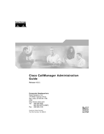
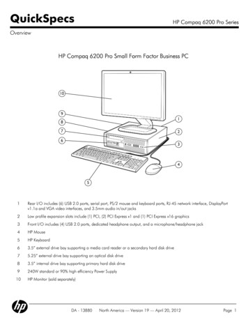
KEY PRINCIPLESHow Should Supporting Documentation be Prepared?1 RCNY §5000-01(g)ECC 101.5.2.3ECC 103 Identify a Correct Code Version to Follow- Job applications filed on and after October 3, 2016 must comply with the 2016 NYCECC.- Job applications filed between January 1, 2015 and October 2, 2016 must comply with the 2014 NYCECC.- See Energy Code Version Table to identify which ECC Code version is applicable for a particular job application. Identify Correct Code Sections to Follow- Mandatory provisions must be satisfied by all applications, whereas Prescriptive provisions must be satisfied by applications that seek to provecompliance prescriptively.- Applicable Code sections must be carefully identified and selected according to the job application/project type.- For a Commercial building application, the Single chosen Code (NYCECC or ASHRAE; indicated as the Code compliance path on PW1–Section 10)must be referenced throughout the entire set of construction documents.Figure GE-2.2016 NYCECC and Applicable Job TypesResidential Buildings2016 NYCECCCommercial Buildings w.NYCECC as Code Compliance PathCommercial Buildings w.ASHRAE as Code Compliance PathNew BuildingsExisting BuildingsNew BuildingsExisting BuildingsNew BuildingsExisting BuildingsvvvvvvChapter 1AdministrationvvChapter R2DefinitionsvvChapter R3General RequirementsvvChapter R4Residential Energy EfficiencyvChapter R5Existing BuildingsChapter R6Referenced StandardsvAppendix RARecommended Procedure 1vAppendix RBSolar Ready Provisions 2vChapter C2DefinitionsvvChapter C3General RequirementsvvChapter C4Commercial Energy EfficiencyvChapter C5Existing BuildingsChapter C6Referenced StandardsAppendix CAASHRAE 90.1-2013 with NYC Modifications 3vvvvvComplete Code Section Title1. Recommended Procedure For Worst-Case Testing of Atmospheric Venting Systems Under R402.4 Or R405 Conditions 5 ACH 502. Solar-Ready Provisions – Detached One- and Two-Family Dwellings, Multiple Single-Family Dwellings (Townhouses)3. Modified National Standard for Buildings, Except For Low-Rise Residential BuildingsGENERAL [GE - 2]BUILDING ENVELOPEMECHANICAL SYSTEMSLIGHTING & ELECTRICAL POWEROTHER REQUIREMENTS
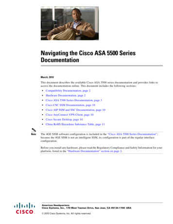
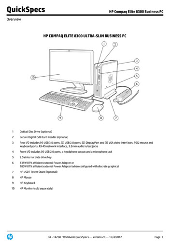
KEY PRINCIPLESHow Should Supporting Documentation be Prepared?1 RCNY §5000-01(g)ECC 101.5.2.3ECC 103 Label Energy Design Elements Consistently Among Drawings- Identification keys for all proposed energy design elements, such as wall types, window/door types, light fixture types, mechanical equipmentsystems, etc., must be consistent between Supporting Documentation and Energy Analysis. Values and Descriptions Must Match- Specifications (in values and descriptions) of energy design elements reported in Energy Analysis must be validated through SupportingDocumentation. For example, Energy-Code-relevant specifications (e.g., insulation type, R-value, U-factor, luminaire type, luminaire wattage,equipment size, equipment efficiency, etc.) declared in the COMcheck energy analysis, but not identified in the construction documents will not beaccepted for Energy Code compliance.- Total numbers reported in Energy Analysis must be validated through Supporting Documentation. For example, the gross values such as exteriorwall/fenestration areas, roof/floor areas, luminaire/equipment counts, area-weighted average values, etc. listed in the Tabular energy analysismust be easily identified in the drawings, schedules, and/or diagrams provided in the construction documents.Figure GE-3.Sample Lighting Fixture Layout Plan (top left),Matching Fixture Schedule (top right), andMatching Interior Lighting COMcheck Report (bottom right)GENERAL [GE - 3]BUILDING ENVELOPEMECHANICAL SYSTEMSLIGHTING & ELECTRICAL POWEROTHER REQUIREMENTS
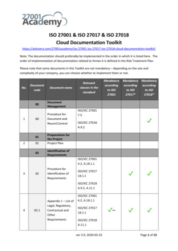
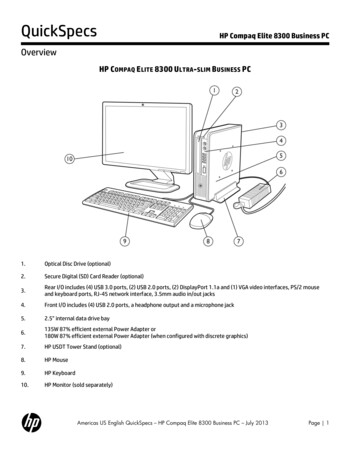
KEY PRINCIPLESHow Should Supporting Documentation be Prepared?1 RCNY §5000-01(g)ECC 101.5.2.3ECC 103 Specific Design Data in Proper Locations- Specific design values and characteristics proposed for the work scope in the application must be provided in the construction documents insufficient detail and clarity. For example, window schedules on drawings must list each proposed window assembly’s U-factor, SHGC, air leakagerating, and Visible Transmittance (as required) values furnished/published by the respective window manufacturer.- Notes directly relevant to achieve the proposed design must be provided in the construction documents in sufficient detail and clarity. In otherwords, mere duplicates of general Energy Code sections placed on the drawings will not be construed as Energy Code compliance.- In proper locations within construction documents, construction data must be presented. For example, 1) HVAC mechanical equipment schedulesand a sequence-of-operations narrative must be found on Mechanical drawings; 2) Lighting control notes must be placed in conjunction withlighting fixture plans and schedules on drawings (typically on RCP drawings). List of Progress Inspections on EN- Sheet- All applicable progress inspections required for Energy Code compliance must be listed on an EN- labeled sheet in tabular format as shown in 1RCNY §5000-01(h), and must match those identified on the TR8.AIR HANDLING UNIT SCHEDULEAIR FLOWTAG LOCATIONROOFCHILLED WATERAREAAIRMINEAT EAT LATSERVED FLOW SUPPLY OA RETURN TSP BHP HP PH/V/RPM Db Wb DbCFMAHU-1SUPPLY FAN3 NORTH VAVCFMCFMINCFMRECOVERERYWHEELHOT WATERLATWbTOT. SENS.TOT. SENS.FLOW EWT LWT EAT LATFLOW EWT LWTCAP CAP.CAP CAP F F F FMBHMBHGPM F F F F MBHMBHGPM3/460/17526000 5500 20500 4.7 23.5 25800675554380270474258 459027049480 F F160 140ENTHALPY%NOTE 3NOTES:1. PROVIDE MOTORIZED SHUT-OFF DAMPER AT THE OA INTAKE WITH MAXIMUM LEAKAGE RATE OF 4 CFM/SF AT 1 IN. WG. DAMPER SHALL CLOSE WHEN THE UNIT IS OFF.2. IN ECONOMIZER MODE, MINIMUM OCCUPIED AIRFLOW SETPOINT ON VAV TERMINALS SHALL BE AUTOMATICALLY RESET BASED ON PERCENTAGE OF OUTSIDE AIR ABOVE DESIGN MINIMUM.A. AS PERCENTAGE OF OA DAMPER AT 100% AND AS ECONOMIZER OUTPUT INCREASES FROM 0-100%, MINIMUM AIRFLOW SETPOINT AT TERMINAL UNITS SHALL PROPORTIONATELY RESET LOWER TOMAINTIAN REQUIRED MINIMUM FRESH AIR VENTILATION.B. RESETTING SHALL OCCUR BASED ON INCREEMENTS OF 10% CHANGE OF VALUE OF ECONOMIZER OUTPUT.3. PROVIDE HEAT WHEEL THAT SHALL RECOVER MINIMUM 50% OF THE ENTHALPY. HEATWHEEL SHALL CONTAIN A BYPASS FOR ECONOMIZER MODE.4. AT A MINIMUM, ALL VAV TERMINAL UNITS SERVED BY AN AHU SHALL BE LINKED WITH ASSOCIATED VAV AHU CONTROLLER TO PERFORM THE FOLLOWING FUNCTIONS.A. ZONE OCCUPANCY SCHEDULE (USER DEFINED FROM GRAPHIC INTERFACE) SHALL NORMALLY AUTOMATICALLY SELECT THE OCCUPIED OR UNOCCUPIED OPERATING MODE OF AIR HANDLING UNIT.1) ACTIVATION OF TIMED OVERRIDE SWITCH ON ZONE THERMOSTATS SHALL ONLY RESET ZONE HEATING AND COOLING SETPOINTS TO “OCCUPIED” VALUES, BUT SHALL NOT AFFECT OTHERWISESCHEDULED UNOCCUPIED OPERATING MODE OF AIR HANDLING UNIT.B. DUCT STATIC PRESSURE RESET AS DESCRIBED IN FAN CONTROL SECTION.C. DISCHARGE AIR TEMPERATURE SETPOINT –OPTIMIZED AS DESCRIBED IN THE DISCHARGE TEMPERATURE CONTROL SECTION.5. FAN POWER LIMITATION CHECK -- PER Table C403.2.12.1(1)HP CFM x 0.001525 26000 x 0.0015 39 OKGENERAL [GE - 4]BUILDING ENVELOPEFigure GE-4. Sample Mechanical Equipment Schedule and NotesMECHANICAL SYSTEMSLIGHTING & ELECTRICAL POWEROTHER REQUIREMENTS
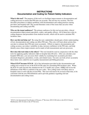
ENERGY ANALYSIS(to demonstrate ECC Compliance in conjunction with Supporting Documentation)Refer to Quick Reference Guide: How to Demonstrate Energy Code Compliance1 RCNY §5000-01(f)ECC 101.5.2.2Figure GE-5Energy Analysis MethodsGENERAL [GE - 5]BUILDING ENVELOPEMECHANICAL SYSTEMSLIGHTING & ELECTRICAL POWEROTHER REQUIREMENTS
How-to Guide:Supporting DocumentationIn Compliance with2016 New York City Energy Conservation Code GENERAL BUILDING ENVELOPE MECHANICAL SYSTEMS LIGHTING & ELECTRICAL POWER OTHER REQUIREMENTSNOTE: In this How-To Guide: Supporting Documentation, selected Energy Code provisions have been generalized, summarized, rephrased, and/or highlighted. This guide is intended: 1) Toprovide general guidance for the job applications seeking compliance with the 2016 NYCECC; 2) Not to replace or represent the entire 2016 NYCECC and related regulations of the City ofNew York and the Department of Buildings; and 3) Not to provide complete compliance solutions for any particular type of job or work. Comprehensive mandates, applicability, exemptions,exceptions and options will be found in the 2016 NYCECC and related regulations of the City of New York and the Department of Buildings.
OPAQUE ENVELOPE ASSEMBLIES Minimum R-value- For each building envelope type (e.g., roof, above-grade/below-grade walls, floors over unconditioned space, etc.), its section detailmust indicate that the R-value of the insulation meets or exceeds the minimum allowed R-value prescribed for the envelope type(e.g., R-values shown in Table C402.1.3).R402.3C402.1.35.5.3- Specifically, in the assembly details, clearly call out each of the proposed insulation type, thickness and the manufacturerpublished R-value to satisfy the thermal requirements for the envelope assembly type. Maximum U-factor- Alternatively, it must be demonstrated that the proposed assembly’s calculated U-factor value does not exceed the maximumallowed U-factor value prescribed for the envelope type (e.g., U-factors shown in Table C402.1.4).- In the calculation of the overall assembly’s U-factor, thermal performance values (e.g., R-value, U-factor, C-factor, etc.)corresponding to the assembly detail must be quoted from Appendix A of ASHRAE 90.1-2013. U-factor calculation methods mustalso be in accordance with Appendix A.R402.3C402.1.45.5.3 NOTE: One common error in the Ufactor calculation is misrepresentingthermal values of assembly layers(e.g., face brick, gypsum board, airfilms, etc.) from unapproved sources.Figure BE-1. Sample Wall Assembly & Area-Weighted U-factor CalculationGENERALBUILDING ENVELOPE [BE - 1]MECHANICAL SYSTEMSLIGHTING & ELECTRICAL POWEROTHER REQUIREMENTS
DOORS & WINDOWS – FENESTRATION IN THE ENVELOPE U-factor and SHGC values- For each fenestration type (e.g., fixed/operable window, skylight, exterior door, storefront, etc.), U-factor and Solar Heat GainCoefficient (SHGC) values must be specified in the window/door schedule on drawings and must not exceed the maximum allowedvalues in the fenestration requirements (e.g., Table C402.4).R402.3C402.45.5.4.35.5.4.4- Next to the U-factor and SHGC values specified in the schedule, provide the fenestration assembly manufacturer’s information (e.g.,‘ABC Windows/def 9000 series, or Approved equal’) that will satisfy the U-factor and SHGC requirements. Air Leakage Rate and Visible Transmittance (VT)- The window/door schedule on drawings must specify the air leakage rate of each proposed fenestration assembly type todemonstrate that the air leakage of fenestration assemblies do not exceed the maximum allowed leakage rate.- Where required, the window/door schedule must identify Visible Transmittance (VT) of the proposed glazed fenestrationproducts to meet the provisions in the applicable Code 02.4, C405.2.35.5.4.6WINDOW & DOOR SCHEDULETAGTYPEMATERIALNOMINAL DIM.(W X H)MANUFACTURER - MODEL NO.ASSEMBLYU-FACTORSHGCVTAIR LEAKAGERATE(CFM/SF)W1FIXEDANNO.ALUMINUM7'-0" X 7'-0"ABC WINDOWS - D999 SERIESOR APPROVED EQUAL0.330.380.510.16W1AFIXED & CASEMENTANNO.ALUMINUM7'-0" X 7'-0"ABC WINDOWS - D999 SERIESOR APPROVED EQUAL0.350.390.510.18W2CASEMENTANNO.ALUMINUM4'-6" X 2'-3"ABC WINDOWS -EF00 SERIESOR APPROVED " X 5'-2"SKL CORP. - GHT000 SERIESOR APPROVED EQUAL0.400.380.50.18ANNO.VARIES; SEE A-301 305 GLD CO. - STR #Z111 ORALUMINUM FOR LOCATIONS & DIM. APPROVED EQUAL0.360.380.530.05GLASS/METAL3'-0" X 7'-6"GLD CO. - STR #Z111 ORAPPROVED EQUAL0.600.380.530.18METAL3'-0" X 7'-0"OPQ COMPANY RST-#22-33OR APPROVED EQUAL0.55N/AN/A0.18W5D1D2STOREFRONT - FIXEDGLAZINGSTOREFRONT ENTRANCE GLASSDOOROPAQUE SWINGINGDOORFigure BE-2. Sample Windows & Doors Schedule Fenestration U-factor values must be the ‘whole assembly’ U-factor, instead of ‘center-of-glass’ U-factor, and must be furnished by the manufacturer. Differentiate Fixed and Operable windows’ U-factor values in the window schedule where required, as the Code-prescribed maximum U-factors for Fixedand Operable windows may vary depending on the referenced Code.GENERALBUILDING ENVELOPE [BE - 2]MECHANICAL SYSTEMSLIGHTING & ELECTRICAL POWEROTHER REQUIREMENTS
FENESTRATION AREA Maximum Vertical Fenestration Area (when following ECC)- Maximum vertical fenestration area (excl. opaque doors & spandrel panels):- Maximum vertical fenestration area (excl. opaque doors & spandrel panels):30% of the gross above-grade wall area40% of the gross above-grade wall area withcertain requirementsSee Section C402.4.1.1 for all requirements. (e.g., daylight responsive controls).- The percentage value of the total vertical fenestration area of job applications must be computed and noted on an EN- labeled drawingin conjunction with building elevations or elevation diagrams.- When vertical fenestration area 40%:C402.4.1C502.2.1ASHRAE must be chosen as Code Compliance Path; ECC does not allow 40%.(Either COMcheck or Energy Modeling may be used for the energy analysis.) Maximum Vertical Fenestration Area (when following ASHRAE)5.5.4.2.1- Maximum vertical fenestration area (excluding opaque doors and spandrel panels): 40% of the gross wall area- When vertical fenestration area 40%, Energy Code compliance may be demonstrated through either COMcheck (with envelopetradeoff) or Energy Modeling (total building performance) energy analysis method. Skylight Fenestration Area (when following ECC)- Maximum skylight fenestration area:3% of the gross roof area- Maximum skylight fenestration area with daylight responsive controls:5% of the gross roof areaWhen 5%: ASHRAE must be chosen.C402.4.1C402.4.2- Minimum skylight fenestration area requirement:Minimum 3% of the gross roof area, or Minimum 1% ‘Skylight Effective Aperture’ See Section C402.4.2 for the spaces where minimum skylight fenestration area is required. For ‘Skylight Effective Aperture,’ refer to Equation 4-4 in Section C402.4.2. Skylight Fenestration Area (when following ASHRAE)- Maximum skylight fenestration area:- Maximum skylight fenestration area with certain requirements: See Section 5.5.4.2.2 for all requirements.3% of the gross roof area6% of the gross roof areaWhen 6%: Either COMcheck (with envelope tradeoff)or Energy Modeling may be used to demonstrate compliance.5.5.4.2.25.5.4.2.3- Minimum skylight fenestration area requirement:Minimum 3% of the gross roof area, or Minimum 1% ‘Skylight Effective Aperture’ See Section 5.5.4.2.3 for the spaces where minimum skylight fenestration area is required.GENERALBUILDING ENVELOPE [BE - 3]MECHANICAL SYSTEMSLIGHTING & ELECTRICAL POWEROTHER REQUIREMENTS
AIR BARRIER Continuous Air BarrierTo ensure air barrier continuity in the building thermal envelope, drawings must specify applicable air barrier construction methods(Section C402.5.1.1), and indicate that the building envelope is composed of 1) building materials not exceeding maximum allowedair permeability (Section C402.5.1.2.1), and/or 2) assemblies not exceeding allowed maximum air leakage (Section C402.5.1.2.2).C402.5.15.4.3.1.25.4.3.1.3 Openings in the Building EnvelopeDrawings must identify specific construction methods, configuration, devices and/or performance standards to limit air leakage inparticular envelope areas including, but not limited to, the following:1) Fenestration and doors: Maximum allowed air leakage.2) Outdoor air intakes and exhaust openings: Shutoff dampers – Motorized unless gravity dampers are allowed.3) Doors/Access Openings to shafts, chutes, vents, stairways and elevator lobbies: Gasketting, weatherstripping, and sealing.4) Loading dock: Weatherseals to restrict infiltration.5) Vestibules: Plan configuration and self-closing devices on doors.6) Recessed lighting: Luminaires installed in building envelope to be: a) IC-rated, b) Labeled with the Code-prescribed maximumair leakage rate, and c) Sealed with gasket or caulk.a) Code-Compliant Planb) Non-Compliant /5.4.3.1.1c) Acceptable Plan with specific notes requiring future complianceFigure BE-4.Sample Vestibule Plan ConfigurationsGENERALBUILDING ENVELOPE [BE - 4]MECHANICAL SYSTEMSLIGHTING & ELECTRICAL POWEROTHER REQUIREMENTS
AIR LEAKAGE TESTING & AIR BARRIER CONTINUITY PLAN Whole Building Air Leakage Testing- For new Residential buildings, mandatory air leakage testing must be specified to ensure the air leakage rate does not exceed 3air changes per hour (3 ACH) at 50 Pascals.- For Residential buildings with 2 to 7 dwelling units within the building envelope, and with 8 or more dwelling units within thebuilding envelope, drawings may identify alternate testing procedures of sample “testing unit” verification methods as specified inthe Code.R402.4.1.2R402.4.1.3C402.5.1.35.4.3.5- For new Commercial buildings 25,000 to 49,999 sf in the conditioned space floor area, and 75 ft or less in height, mandatory airleakage testing must be specified to ensure the air leakage rate does not exceed 0.4 cfm/ft2 of envelope area at 75 Pascals. Air Barrier Continuity Plan- For new Commercial buildings 50,000 sf or greater in the conditioned space floor area, an Air Barrier Continuity Plan must beprepared and implemented.C402.5.1.35.4.3.5- The Air Barrier Continuity Plan must specify (1) List of typical joint and seam conditions, (2) Testing method options for each, (3)Sampling rates of test, (4) Quality control process in test, and (5) Guidelines for test reports and final certificates. Meeting the Air Leakage Requirements of the 2012 IECC is a general air leakagereference guide provided by the U.S. Department of Energy: Building Energy CodesProgram.Please use the guide in the link for general reference purposes only as 2016 NYCECCis in parallel with 2015 IECC, a more recent IECC Code version.Figure BE-5. Blower door installed for air leakage testing at a construction siteSource: ERALBUILDING ENVELOPE [BE - 5]MECHANICAL SYSTEMSLIGHTING & ELECTRICAL POWEROTHER REQUIREMENTS
THERMAL BRIDGING IN BUILDING ENVELOPE Address the Thermal Bridging!- Drawings must address all thermal-bridging-prone areas in the building envelope either by specifying supplemental insulationmaterials in such areas (prescriptive path), or by reporting the inferior thermal resistance values of the areas individually in theenergy analysis (envelope trade-off path).R402C402- Thermal bridging commonly occurs in floor slab/joist edges, floor and balcony connections, slab-on-grade conditions, and roof andwall connection areas among others.- Job applications seeking to meet the building envelope requirements prescriptively must prove that each of the thermal-bridgingprone areas meet the minimum insulation requirement. Trade-Offs in the Envelope for Residential Buildings – Total UA Alternative- Alternatively, for Residential buildings, assembly details for building envelope components must demonstrate that:Total building thermal envelope UA Total UA resulting from the Code-prescriptive U-factors(Sum of Assembly area x its U-factor)R402.1.5(Sum of Assembly area x Code U-factor value for the assembly type)- This could be verified by the REScheck envelope energy analysis by entering all building envelope components of varying thermalresistance values. Trade-Offs in the Envelope for Commercial Buildings – Component Performance Alternative- Alternatively, for Commercial buildings, assembly details for building envelope components must demonstrate the compliance withinsulation requirements by satisfying the formula in Section C402.1.5.- Compliance could be verified with the COMcheck envelope energy analysis by entering all building envelope components’ varyingthermal values, as this Alternative method has been built into the COMcheck software.C402.1.55.6.1.1Figure BE-6.Sample Slab Edge Detail &Matching Envelope COMcheck ReportGENERALBUILDING ENVELOPE [BE - 6]MECHANICAL SYSTEMSLIGHTING & ELECTRICAL POWEROTHER REQUIREMENTS
THERMAL BRIDGING IN BUILDING ENVELOPEFigure BE-7.Sample Balcony Edge Details &Matching Envelope COMcheck ReportsGENERALBUILDING ENVELOPE [BE - 7]MECHANICAL SYSTEMSLIGHTING & ELECTRICAL POWEROTHER REQUIREMENTS
EQUIPMENT PENETRATIONS IN BUILDING ENVELOPE Calculation of Equipment Penetration AreasWhen mechanical equipment listed in Table C403.2.3(3) or Table 6.8.1-4 are proposed in a New Commercial building application:- Drawings must identify the calculated total area of the equipment penetrations in the opaque above-grade walls by the supportingdiagrammatic building elevations.- Drawings must also identify the percentage of the total equipment penetration area out of the total opaque above-grade wall area.C402.1.4.25.5.3 U-factor 0.5 for Penetration Areas 1% of Opaque Walls- If the total area of penetrations from mechanical equipment specified above exceeds 1% of the total opaque above-grade wallarea, the equipment penetration area must be identified as a separate wall assembly with a default U-factor of 0.5.- Accordingly, in the envelope energy analysis (e.g., Component performance alternative calculation, COMcheck, or Energy Modeling)the total equipment penetration area must be entered as a separate exterior wall type of proposed U-factor 0.5 and budget Ufactor identical to the surrounding wall.C402.1.4.2C402.1.55.6.1.1Figure BE-8.Sample Envelope COMcheck report withEquipment Penetration Area entered as a separate opaque wall typeGENERALBUILDING ENVELOPE [BE - 8]MECHANICAL SYSTEMSLIGHTING & ELECTRICAL POWEROTHER REQUIREMENTS
FUEL-BURNING APPLIANCES Thermally Isolated and Insulated RoomsWhen open combustion air ducts provide combustion air to open combustion fuel-burning appliances (e.g., natural draft boilers orfurnaces) in a room, the room must be thermally isolated from the building it serves, and sealed and insulated to meet therequirements of Table R402.1.2, Table C402.1.3 or C402.1.4.R402.4.4C402.5.3 Direct Vent AppliancesIf the fuel-burning appliances are to be located in a room within the building thermal envelope, the appliances must be identified asdirect vent appliances with both intake and exhaust pipes installed continuous to the outside.R402.4.4C402.5.3 Fireplaces with Tight-fitting Doors or DampersFireplaces or fireplace units that are designed to allow an open burn must be specified with tight-fitting flue dampers or tight-fittingdoors labeled with applicable Code-required UL listings.R402.4.2C402.2.7Figure BE-9. A direct-vent sealed-combustion furnace with dedicated pipes for combustion air and exhaust installed continuous to the outsideSource: basc.pnnl.gov/imagesGENERALBUILDING ENVELOPE [BE - 9]MECHANICAL SYSTEMSLIGHTING & ELECTRICAL POWEROTHER REQUIREMENTS
FENESTRATION ORIENTATION – ASHRAE-ONLY, PRESCRIPTIVE* REQUIREMENTS The Vertical Fenestration on the West- and East-Oriented Walls(must comply with either A or B below)A) Limiting Fenestration Area5.5.4.5B) Limiting SHGC Values5.5.4.5West-oriented vertical fenestration area must be 1/4 of the Total vertical fenestration area,andEast-oriented vertical fenestration area must be 1/4 of the Total vertical fenestration area.West-oriented vertical fenestration area x SHGC for West-oriented fenestration must be 1/4 of the Total vertical fenestration area x Code-prescribed maximum SHGC for Climate Zone 4a (from Table 5.5-4),andEast-oriented vertical fenestration area x SHGC for East-oriented fenestration must be 1/4 of the Total vertical fenestration area x Code-prescribed maximum SHGC for Climate Zone 4a (from Table 5.5-4).* Prescriptive requirements MUST be met whenPrescriptive energy analysis method (e.g., Tabularanalysis) is chosen to demonstrate Energy Codecompliance. If COMcheck or Energy Modeling is usedfor the energy analysis, the software programautomatically takes into account the verticalfenestration areas and SHGC values on the west andeast-oriented wall in its computation.Figure BE-10.Buildings on Manhattan’s grid 29 off of true north are likelyto have no West-oriented vertical fenestrationGENERALBUILDING ENVELOPE [BE - 10]MECHANICAL SYSTEMSLIGHTING & ELECTRICAL POWEROTHER REQUIREMENTS
RESIDENTIAL BUILDING ENVELOPE Blown or Sprayed Roof/Ceiling Insulation- The thickness of blown-in or sprayed roof/ceiling insulation (fiberglass or cellulose) in the attic must be indicated on markers forevery 300 sf.R303.1.1.1- The markers must indicate minimum initial installed thickness with numbers of a minimum of 1 inch in height. Protection of Exposed Foundation InsulationRigid, opaque and weather-resistant protective coverings must be applied to protect the insulation over the exterior of basementwalls, crawl space walls and the perimeter of slab-on-grade floors.R303.2.1 Slab-on-Grade Floor Insulation at the Perimeter- Slab-on-grade floors with a floor surface 12” below grade must be insulated at the perimeter with minimum R-10 for Unheatedslab, and minimum R-15 for Heated slab.R402.2.10- The insulation must be extended downward or horizontally (as shown in the Figures below) a minimum of 4’ for Climate Zone 4A.- Insulation extending away from the building must be protected by pavement or by minimum 10” of soil. Insulation at Tenant Separation WallsFire-separated walls between dwelling units in two-family houses or townhouses must be insulated at a minimum R-value of R-10.R402.4.6Figure BE-11.a.Protection of Insulation Over the Grade BeamSource: basc.pnnl.gov/imagesFigure BE-11.b.Slab Insulation MethodsSource: basc.pnnl.gov/imagesGENERALBUILDING ENVELOPE [BE - 11]MECHANICAL SYSTEMSLIGHTING & ELECTRICAL POWEROTHER REQUIREMENTS
RESIDENTIAL BUILDING ENVELOPE Insulation in Ceilings- Ceiling with Attic Spaces: Minimum R-49; or Uncompressed R-38 covering 100% of ceiling and extended over the wall top plate atthe eaves (See Figures below).R402.2.1R402.2.2- Ceiling without Attic Spaces: When installation of required minimum R-49 insulation in 100% of the ceiling is unachievable, R-30insulation is allowed for a maximum 500 sf or maximum 20% of the total insulated ceiling area, whichever is less. If partial R-30insulation is proposed, provide roof area calculations with roof plan diagrams. Access Hatches and Doors
4. at a minimum, all vav terminal units served by an ahu shall be linked with associated vav ahu controller to perform the following functions. a. zone occupancy schedule (user defined from graphic interface) shall normally automatically select the oc