Transcription
Physical Design of CMOS IntegratedCircuitsDae Hyun KimEECSWashington State University
References John P. Uyemura, “Introduction to VLSI Circuits and Systems,” 2002.– Chapter 5
Goal Understand how to physically design (manually draw) CMOSintegrated circuits (ICs)
Custom Design FlowDesign specificationSchematic design(Transistor-level netlist)An inverter (spec: width, height, .)𝑥𝑥𝑓𝑓 𝑥𝑥̅Layout (physical) designDRC (Design Rule Check)LVS (Layout vs. Schematic)RC extractionSPICE-level netlistCharacterizationTiming/power info.Library
Schematic Editor Cadence VirtuosoSource: /attachments/4467d1343409050-schematic-jpg?s a9af157432886096c1b713b17c65f4be
Layout Editor Cadence VirtuosoSource: obal/en oso-zambebi-xl-600px.jpg/ jcr content/renditions/original.img.png
Layout Design Draw polygons (rectilinear objects) in each layer– Rectangles– Paths Layers (Real)––––––––n-wellp-wellActive (n ndiff)Active (p pdiff)PolyContactMetal (m1, m2, m3, .)Via (v12, v23, v34, .) Metal 1 Layers (Virtual)– Cell boundary– Labels– PinsVDD, VSS, A, Z
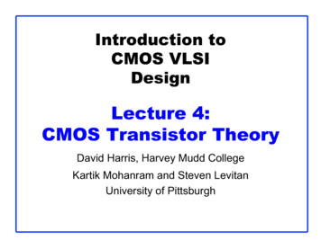
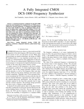
InverterSubstrate contactM3M2M1p n n p-epip p n-welln substrateSubstrate contact
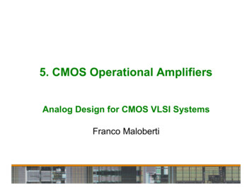
Design ts Poly
Design ts Implant
Design ts Active
Design ts Contact
Design ts Metal 1
Design ts Via12
Layouts INV X1, INV X2, INV X4, INV X8
Layouts INV X8, INV X16, INV X32
Layouts NAND2 X1, NOR2 X1
Layouts BUF X1, BUF X2, BUF X4
Layouts AND2 X1, AND3 X1, AND4 X1
Layouts XOR2 X1, XNOR2 X1
Layouts MUX2 X1
Layouts FA X1 (Full adder)
Layouts DFF X1 (D F/F)
Transistor Folding (A Layout Technique) INV X16
Layout Generation Draw a layout.– Output: GDSII format Design rule check (DRC) Prepare a schematic (netlist).– A text file Layout vs. Schematic (LVS)– Layout netlist 1– Schematic netlist 2– LVS checks whether netlist 1 is equal to netlist 2. Parasitic RC extraction– Output: A SPICE netlist with parasitic RC Timing/power simulation and characterization
Channel Length and Width 𝐿𝐿𝑒𝑒𝑒𝑒𝑒𝑒 𝐿𝐿 𝐿𝐿– 𝐿𝐿𝑒𝑒𝑒𝑒𝑒𝑒 : effective channel length– 𝐿𝐿: drawn channel length 𝑊𝑊𝑒𝑒𝑒𝑒𝑒𝑒 𝑊𝑊 ��𝐿𝐿(Drawn)𝑊𝑊(Drawn)Gn n 𝐿𝐿𝑒𝑒𝑒𝑒𝑒𝑒p
Terminologies Twin-tub technology– Two separate wells are created. n-well for pFETs p-well for nFETs Latch-upSource: mos.html
Digital VLSI Design Placement– Places transistors in a layout. Routing– Power/Ground Connect all the 𝑉𝑉𝐷𝐷𝐷𝐷 lines to 𝑉𝑉𝐷𝐷𝐷𝐷 . Connect all the 𝑉𝑉𝑆𝑆𝑆𝑆 lines to 𝑉𝑉𝑆𝑆𝑆𝑆 . Reduce IR drop.– Clock Connect all the clock sinks to a main clock source pin. Achieve zero skew.– Signal
Standard Cell-Based Digital VLSI Design Power/Ground routingDie area (Layout)I/O cellsCore areaPower (Outer ring)Ground (Inner ring)Metal 1Metal 2GoundPower
Standard Cell-Based Digital VLSI DesignVia1
Standard Cell-Based Digital VLSI Design Standard cells––––have a fixed height.have different widths.have ports (input/output pins) generally in the Metal 1 layer.have some obstacles in the Metal 1 layer (for internal routing). Routing– uses only metal and via layers (doesn’t use any other layers).– routes the standard cell ports and primary I/O ports based on a givennetlist.
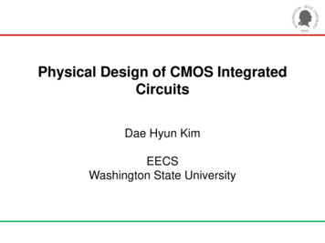
Standard Cell-Based Digital VLSI Design BUF X1VDD portCell boundaryObstruction (M1)A (input, M1)Z (output, M1)VSS portLayout
Automatic Placement
Automatic Routing
FET Sizing Theory– 𝑰𝑰 𝝁𝝁 𝒄𝒄𝒐𝒐𝒐𝒐 – 𝑹𝑹 𝟏𝟏𝜷𝜷 (𝑽𝑽𝑮𝑮 𝑽𝑽𝑻𝑻 )Motivation 1𝑾𝑾𝑳𝑳 (𝑽𝑽𝑮𝑮 𝑽𝑽𝑻𝑻 ) 𝑽𝑽𝑫𝑫𝑫𝑫𝑳𝑳𝑾𝑾– pFETs and nFETs have different mobility values. 𝜇𝜇𝑛𝑛 𝜇𝜇𝑝𝑝– Thus, if an nFET and a pFET networks have the same transistor sizes, theirdelay values are different. Motivation 2– Minimum-size FETs might not provide enough drive strength. Goal– Achieve perfectly-balanced delay values (from Motivation 1).– Satisfy delay constraints (from Motivation 2). Mobility ratio– 𝝁𝝁𝒏𝒏 𝒓𝒓 𝝁𝝁𝒑𝒑 (𝒓𝒓 𝟏𝟏)– 𝑹𝑹𝒑𝒑 𝒓𝒓 𝑹𝑹𝒏𝒏
FET Sizing Theory– 𝑰𝑰 𝝁𝝁 𝒄𝒄𝒐𝒐𝒐𝒐 – 𝑹𝑹 𝟏𝟏𝜷𝜷 (𝑽𝑽𝑮𝑮 𝑽𝑽𝑻𝑻 )𝑾𝑾𝑳𝑳 (𝑽𝑽𝑮𝑮 𝑽𝑽𝑻𝑻 ) 𝑽𝑽𝑫𝑫𝑫𝑫𝑳𝑳𝑾𝑾– The drive strength (current) is proportional to 𝑊𝑊 inversely proportional to 𝐿𝐿– The input capacitance is proportional to 𝐿𝐿 and 𝑊𝑊.– If 𝐿𝐿 increases The input capacitance goes up.The drive strength goes down (or the output resistance goes up).The cell area goes up.Thus, do not increase 𝐿𝐿 (i.e., use the minimum channel length).– If 𝑊𝑊 increases The input capacitance goes up.The drive strength goes up (or the output resistance goes down).The cell area goes up.If the input capacitance overhead is small, upsizing FETs reduces the delay of thedownstream net.
FET Sizing Theory– The FET width cannot be reduced infinitely (design rules).– Suppose the minimum transistor length and width are 𝐿𝐿0 and 𝑊𝑊0 ,respectively.– Then, Minimum-size nFET – Resistance: 𝑅𝑅𝑛𝑛 Minimum-size pFET – Resistance: 𝑅𝑅𝑝𝑝Transistor upsizing– If the size of an nFET is Resistance:𝑅𝑅𝑛𝑛𝑘𝑘– If the size of a pFET is ���0 𝑛𝑛𝑊𝑊0:𝐿𝐿0 𝑝𝑝This is a 1X nFET.This is a 1X pFET.𝑘𝑘 𝑊𝑊0,𝐿𝐿0 𝑛𝑛𝑘𝑘 𝑊𝑊0,𝐿𝐿0 𝑝𝑝it is a 𝑘𝑘X nFET.it is a 𝑘𝑘X pFET.
FET Sizing (Matching) Example: Inverter– 𝜇𝜇𝑛𝑛 𝟐𝟐 𝜇𝜇𝑝𝑝 (i.e., 𝑅𝑅𝑝𝑝 2𝑅𝑅𝑛𝑛 �𝑖𝑖𝑖1X𝐶𝐶Minimum-size inverter𝑉𝑉𝑖𝑖𝑖𝑖 1𝑅𝑅 𝑅𝑅𝑛𝑛𝐶𝐶𝑉𝑉𝑖𝑖𝑖𝑖 0𝑅𝑅 𝑅𝑅𝑝𝑝 2𝑅𝑅𝑛𝑛𝐶𝐶Time constant 𝜏𝜏 𝑅𝑅𝑛𝑛 𝐶𝐶𝜏𝜏 2𝑅𝑅𝑛𝑛 𝐶𝐶𝑉𝑉𝑖𝑖𝑖𝑖 1𝑅𝑅 𝑅𝑅 𝑅𝑅𝑛𝑛𝜏𝜏 𝑅𝑅𝑛𝑛 𝐶𝐶𝐶𝐶𝑉𝑉𝑖𝑖𝑖𝑖 0𝑅𝑅𝑝𝑝 𝑅𝑅𝑛𝑛2𝐶𝐶𝜏𝜏 𝑅𝑅𝑛𝑛 𝐶𝐶
FET Sizing (Delay Reduction) Example: Inverter– 𝜇𝜇𝑛𝑛 𝟐𝟐 𝜇𝜇𝑝𝑝 (i.e., 𝑅𝑅𝑝𝑝 2𝑅𝑅𝑛𝑛 ���𝑖𝑖 14X2X2X inverter𝐶𝐶𝑉𝑉𝑖𝑖𝑖𝑖 1𝑅𝑅 𝑅𝑅𝑛𝑛2𝜏𝜏 𝐶𝐶𝑅𝑅𝑛𝑛 𝐶𝐶2𝑅𝑅𝑝𝑝 𝑅𝑅𝑛𝑛2𝐶𝐶𝜏𝜏 𝑅𝑅𝑛𝑛 𝐶𝐶𝜏𝜏 𝑅𝑅𝑛𝑛 𝐶𝐶1X inverter𝑉𝑉𝑖𝑖𝑖𝑖𝐶𝐶𝑅𝑅 𝑅𝑅𝑛𝑛𝑉𝑉𝑖𝑖𝑖𝑖 0𝑅𝑅 𝑉𝑉𝑖𝑖𝑖𝑖 0𝑅𝑅 𝑅𝑅𝑝𝑝 𝑅𝑅𝑛𝑛 42𝜏𝜏 𝑅𝑅𝑛𝑛 𝐶𝐶2𝐶𝐶
FET Sizing NAND2 X1, NOR2 𝑎𝑎4X1X𝑏𝑏𝑏𝑏4XFETs are sized for the worst-case signal path.1X
FET Sizing 𝑓𝑓 𝑎𝑎 𝑏𝑏 𝑐𝑐 ��𝑐𝑐2X2X
FET Sizing – Analytical Approach NAND2 X1– pFETs: Each should be 2X.– nFETs If 𝑎𝑎 is upsized to 𝑥𝑥1 X and 𝑏𝑏 is upsized to 𝑥𝑥2 X (𝑥𝑥1 , 𝑥𝑥2 1)– Resistance of 𝑎𝑎:– Resistance of 𝑎𝑎𝑥𝑥2 The total resistance should be 𝑅𝑅𝑛𝑛 .–𝑅𝑅𝑛𝑛𝑥𝑥1 𝑅𝑅𝑛𝑛𝑥𝑥2 𝑅𝑅𝑛𝑛 1𝑥𝑥1 1𝑥𝑥2 1 For instance, 𝑥𝑥1 , 𝑥𝑥2 2,2 , 3,32, 4, We want to minimize the total area.– Min. 𝑥𝑥1 𝑥𝑥243, 2X𝑎𝑎𝑏𝑏𝑏𝑏𝑥𝑥1 X𝑥𝑥2 X2X
FET Sizing – Analytical Approach Problem– Minimize 𝑓𝑓 𝑥𝑥1 , 𝑥𝑥2 𝑥𝑥1 𝑥𝑥2 under the following constraints. 𝑥𝑥1 , 𝑥𝑥2 11𝑥𝑥1– Solve 1𝑥𝑥2 11𝑥𝑥1 1𝑥𝑥2 1 𝑥𝑥2 𝑥𝑥1𝑥𝑥1 1 𝑓𝑓 𝑥𝑥1 , 𝑥𝑥2 𝑥𝑥1 𝑥𝑥2 𝑥𝑥1 ′ 𝑓𝑓 𝑥𝑥1 2𝑥𝑥1 𝑥𝑥1 1 𝑥𝑥1 2(𝑥𝑥1 1)2 𝑥𝑥1𝑥𝑥1 1𝑥𝑥1 2 2𝑥𝑥1(𝑥𝑥1 1)2 𝑓𝑓 𝑥𝑥1 𝑥𝑥1 2𝑥𝑥1 1 Thus, 𝑓𝑓 is minimized when 𝑥𝑥1 2. In this case, 𝑥𝑥2 is also 2.
FET Sizing – Analytical Approach NAND X𝑛𝑛 (𝑛𝑛-input NAND gate)– pFETs: Each should be 2X.– nFETs If 𝑎𝑎𝑖𝑖 is upsized to 𝑥𝑥𝑖𝑖 X (𝑥𝑥𝑖𝑖 1)– Resistance of 𝑎𝑎𝑖𝑖 :𝑅𝑅𝑛𝑛𝑥𝑥𝑖𝑖 The total resistance should be 𝑅𝑅𝑛𝑛 .– 𝑛𝑛𝑖𝑖 1𝑅𝑅𝑛𝑛𝑥𝑥𝑖𝑖 𝑅𝑅𝑛𝑛 1𝑥𝑥1 1𝑥𝑥2 1𝑥𝑥𝑛𝑛 1 We want to minimize the total area.2X 𝑎𝑎2𝑎𝑎12X 𝑎𝑎𝑛𝑛𝑥𝑥1 X𝑎𝑎2𝑥𝑥2 X𝑎𝑎𝑛𝑛𝑥𝑥𝑛𝑛 X – Min. 𝑛𝑛𝑖𝑖 1 𝑥𝑥𝑖𝑖 𝑥𝑥1 𝑥𝑥2 𝑥𝑥𝑛𝑛𝑎𝑎12X
FET Sizing – Analytical Approach Problem– Minimize 𝑓𝑓 𝑥𝑥1 , 𝑥𝑥2 , , 𝑥𝑥𝑛𝑛 𝑥𝑥1 𝑥𝑥2 𝑥𝑥𝑛𝑛 under the following constraints. 𝑥𝑥𝑖𝑖 1 1𝑥𝑥1– Solve Let1𝑥𝑥21𝑥𝑥𝑖𝑖 1𝑥𝑥𝑛𝑛 1 𝑦𝑦𝑖𝑖 . Then, the problem becomes as follows:11– Minimize 𝑓𝑓 𝑦𝑦1 , , 𝑦𝑦𝑛𝑛 𝑦𝑦 𝑦𝑦1– 𝑦𝑦𝑖𝑖 1– 𝑦𝑦1 𝑦𝑦𝑛𝑛 1 𝑦𝑦𝑛𝑛 1 (𝑦𝑦1 𝑦𝑦𝑛𝑛 1 ) 𝑓𝑓 𝑦𝑦1 , , 𝑦𝑦𝑛𝑛 Solve 𝑦𝑦𝑖𝑖 𝑓𝑓 𝑦𝑦1 1𝑦𝑦1 0, ,1𝑦𝑦𝑖𝑖 2 𝑦𝑦𝑛𝑛 111𝑦𝑦𝑛𝑛 𝑓𝑓 𝑦𝑦1 , , 𝑦𝑦𝑛𝑛 1 0.1 𝑦𝑦1 𝑦𝑦𝑛𝑛 1𝑛𝑛2 0– 𝑦𝑦𝑖𝑖 1 (𝑦𝑦1 𝑦𝑦𝑛𝑛 1 ) 𝑦𝑦𝑖𝑖 𝑦𝑦𝑛𝑛1𝑦𝑦1 1𝑦𝑦𝑛𝑛 1 11 (𝑦𝑦1 𝑦𝑦𝑛𝑛 1 ) Thus, 𝑓𝑓 is minimized when 𝑦𝑦1 𝑦𝑦2 𝑦𝑦𝑛𝑛 , i.e., 𝑥𝑥1 𝑥𝑥2 𝑥𝑥𝑛𝑛 . As a result, 𝑥𝑥1 𝑥𝑥2 𝑥𝑥𝑛𝑛 𝑛𝑛.
integrated circuits (ICs) Custom Design Flow Schematic design (Transistor-level netlist) Design specification . Layout (phys