Transcription
6WMM7 Series Motherboard4.BIOS CONFIGURATIONAward's BIOS ROM has a built-in Setup program that allows users to modify thebasic system configuration. This type of information is stored in battery-backedCMOS SRAM so that it retains the Setup information when the power is turnedoff.4.1. ENTERING SETUPPower ON the computer and press Del immediately will allow you to enterSetup. If the message disappears before you respond and you still wish to enterSetup, restart the system to try again by turning it OFF then ON or pressing the"RESET" bottom on the system case. You may also restart by simultaneouslypress Ctrl , Alt , and Del keys.4.2. CONTROL KEYSUp arrowDown arrowLeft arrowRight arrowEsc keyPgUp keyPgDn keyF1 keyF2 keyF3 keyF4 keyF5 keyF6 keyF7 keyF8 keyF9 keyF10 keyMove to previous itemMove to next itemMove to the item in the left handMove to the item in the right handMain Menu - Quit and not save changes into CMOSStatus Page Setup Menu and Option Page Setup Menu Exit current page and return to Main MenuIncrease the numeric value or make changesDecrease the numeric value or make changesGeneral help, only for Status Page Setup Menu and OptionPage Setup MenuReservedReservedReservedRestore the previous CMOS value from CMOS, only forOption Page Setup MenuLoad the default CMOS value from Fail-Saft default table,only for Option Page Setup MenuLoad Optimized defaultsReservedReservedSave all the CMOS changes and exit4-1
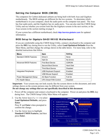
BIOS Configuration4.3. GETTING HELP4.3.1. Main MenuThe on-line description of the highlighted setup function is displayed at thebottom of the screen.4.3.2. Status Page Setup Menu / Option Page Setup MenuPress F1 to pop up a small help window that describes the appropriate keys touse and the possible selections for the highlighted item. To exit the HelpWindow press Esc .4.4. THE MAIN MENUOnce you enter Award BIOS CMOS Setup Utility, the Main Menu (Figure 4.1)will appear on the screen. The Main Menu allows you to select from nine setupfunctions and two exit choices. Use arrow keys to select among the items andpress Enter to accept or enter the sub-menu.CMOS Setup Utility-Copyright( C ) 1984-1999 Award Software4Standard CMOS Features4Frequency/Voltage Control4Advanced BIOS FeaturesLoad Fail-Safe Defaults4Advanced Chipset FeaturesLoad Optimized Defaults4Integrated PeripheralsSet Supervisor Password4Power Management SetupSet User Password4PnP/PCI ConfigurationsSave & Exit Setup4PC Health StatusExit Without SavingESC:QuitF10:Save & Exit Setup : Select ItemTime, Date, Hard Disk Type Figure 4.1: Main Menu4-2
6WMM7 Series Motherboard Standard CMOS FeaturesThis setup page includes all the items in standard compatible BIOS. Advanced BIOS FeaturesThis setup page includes all the items of Award special enhancedfeatures. Advanced Chipset FeaturesThis setup page includes all the items of chipset special features. Integrated PeripheralsThis setup page includes all onboard peripherals. Power Management SetupThis setup page includes all the items of Green function features. PnP/PCI ConfigurationsThis setup page includes all the configurations of PCI & PnP ISAresources. PC Health StatusThis setup page is the System auto detect Temperature, voltage , fan,speed. Frequency/Voltage ControlThis setup page is control CPU’s clock and frequency ratio. Load Fail-Safe DefaultsFail-Safe Defaults indicates the value of the system parameters which thesystem would be in safe configuration. Load Optimized DefaultsOptimized Defaults indicates the value of the system parameters whichthe system would be in best performance configuration.4-3
BIOS Configuration Set Supervisor passwordChange, set, or disable password. It allows you to limit access to thesystem and Setup, or just to Setup. Set User passwordChange, set, or disable password. It allows you to limit access to thesystem. Save & Exit SetupSave CMOS value settings to CMOS and exit setup. Exit Without SavingAbandon all CMOS value changes and exit setup.4-4
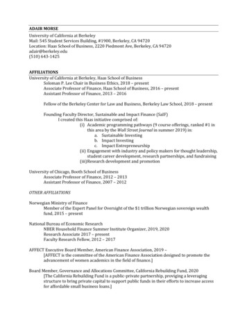
6WMM7 Series Motherboard4.5. STANDARD CMOS FEATURES MENUThe items in Standard CMOS Setup Menu (Figure 4.2) are divided into 9categories. Each category includes no, one or more than one setup items. Usethe arrows to highlight the item and then use the PgUp or PgDn keys toselect the value you want in each item.CMOS Setup Utility-Copyright( C ) 1984-1999 Award SoftwareStandard CMOS FeaturesDate (mm:dd:yy)Thu , Oct 19 1999Item HelpTime (hh:mm:ss)2 : 31 : 24Menu Level 4Press Enter None4IDE Primary MasterChange the4IDE Primary SlavePress Enter NoneDay, month,4IDE Secondary MasterPress Enter NoneYear and4IDE Secondary SlavePress Enter NonecenturyDrive A1.44M, 3.5 in.Drive BNoneFloppy 3 Mode SupportDisabledVideoHalt OnEGA / VGAAll, But KeyboardBase MemoryExtended MemoryTotal Memory640K129024K130048K Move Enter:Select /-/PU/PD:Value F10:Save ESC:Exit F1:General HelpF5:Previous Values F6:Fail-Safe Defaults F7:Optimized DefaultsFigure 4.2: Standard CMOS Features Menu4-5
BIOS Configuration DateThe date format is week , month day year .weekmonthdayyear The week, from Sun to Sat, determined by the BIOS and isdisplay-onlyThe month, Jan. Through Dec.The day, from 1 to 31 (or the maximum allowed in the month)The year, from 1994 through 2079TimeThe times format in hour minute second . The time is calculatedbase on the 24-hour military-time clock. For example, 1 p.m. is 13:00:00. IDE Primary Master, Slave / Secondary Master, SlaveThe category identifies the types of hard disk from drive C to F that hasbeen installed in the computer. There are three types: auto type, manualdefinable type and none type user type is user-definable; Auto type whichwill automatically detect HDD type.Note that the specifications of your drive must match with the drive table.The hard disk will not work properly if you enter improper information forthis category.If you select Manual type, related information will be asked to enter to thefollowing items. Enter the information directly from the keyboard and press Enter . Such information should be provided in the documentation formyour hard disk vendor or the system manufacturer.CYLS.Number of cylindersHEADSnumber of headsPRECOMPwrite precompLANDZONE Landing zoneSECTORSnumber of sectorsIf a hard disk has not been installed select NONE and press Enter .4-6
6WMM7 Series Motherboard Drive A type / Drive B typeThe category identifies the types of floppy disk drive A or drive B that hasbeen installed in the computer.None360K, 5.25 in.1.2M, 5.25 in.720K, 3.5 in.1.44M, 3.5 in.2.88M, 3.5 in. No floppy drive installed5.25 inch PC-type standard drive; 360K byte capacity.5.25 inch AT-type high-density drive; 1.2M bytecapacity (3.5 inch when 3 Mode is Enabled).3.5 inch double-sided drive; 720K byte capacity3.5 inch double-sided drive; 1.44M byte capacity.3.5 inch double-sided drive; 2.88M byte capacity.Floppy 3 Mode Support (for Japan Area)DisabledNormal Floppy Drive.Drive ADrive A is 3 mode Floppy Drive.Drive BDrive B is 3 mode Floppy Drive.BothDrive A & B are 3 mode Floppy Drives.VideoThe category detects the type of adapter used for the primary systemmonitor that must match your video display card and monitor. Althoughsecondary monitors are supported, you do not have to select the type insetup.EGA/VGAEnhanced Graphics Adapter/Video Graphics Array. ForEGA, VGA, SVGA, or PGA monitor adaptersCGA 40Color Graphics Adapter, power up in 40 column modeCGA 80Color Graphics Adapter, power up in 80 column modeMONOMonochromeadapter,monochrome adapters4-7includeshighresolution
BIOS Configuration Halt onThe category determines whether the computer will stop if an error isdetected during power up. NO ErrorsThe system boot will not stop for any error that maybe detected and you will be promptedAll ErrorsWhenever the BIOS detects a non-fatal error thesystem will be stoppedAll, But KeyboardThe system boot will not stop for a keyboard error;it will stop for all other errorsAll, But DisketteThe system boot will not stop for a disk error; it willstop for all other errorsAll, But Disk/KeyThe system boot will not stop for a keyboard or diskerror; it will stop for all other errorsMemoryThe category is display-only which is determined by POST (Power On SelfTest) of the BIOS.Base MemoryThe POST of the BIOS will determine the amount of base (orconventional) memory installed in the system.The value of the base memory is typically 512 K for systems with512 K memory installed on the motherboard, or 640 K for systemswith 640 K or more memory installed on the motherboard.Extended MemoryThe BIOS determines how much extended memory is presentduring the POST.This is the amount of memory located above 1 MB in the CPU'smemory address map.4-8
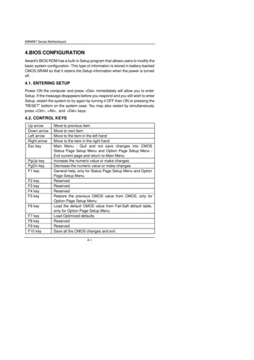
6WMM7 Series Motherboard4.6. Advanced BIOS FeaturesCMOS Setup Utility-Copyright( C ) 1984-1999 Award SoftwareAdvanced BIOS FeaturesVirus WarningDisabledItem HelpCPU CacheEnabledCPU L2 Cache ECC CheckingDisabledMenu Level 4Allows you toQuick Power On Self TestEnabledchoose the VIRUSFirst Boot DeviceFloppyWarning featureSecond Boot DeviceHDD-0For IDE Hard diskThird Boot DeviceLS/ZIPBoot sectorBoot Other DeviceEnabledProtection. If thisSwap Floppy DriveDisabledFunction is enableBoot Up Floppy SeekEnabledAnd someoneBoot Up NumLock StatusONAttempt to writeGate A20 OptionFastData into this areaTypematic Rate SettingDisabled, BIOS will showTypematic Rate (Chars/Sec)6A warningTypematic Delay (Msec)250Message onSecurity OptionSetupScreen and alarmOS Select For DRAM 64MBNon-OS2beepHDD S.M.A.R.T. CapabilityDisabledReport No FDD For WIN 95No Move Enter:Select /-/PU/PD:Value F10:Save ESC:Exit F1:General HelpF5:Previous Values F6:Fail-Safe Defaults F7:Optimized DefaultsFigure 4.3: Advanced BIOS Features Setup Virus WarningIf it is set to enable, the category will flash on the screen when there is anyattempt to write to the boot sector or partition table of the hard disk drive.The system will halt and the following error message will appear in themean time. You can run anti-virus program to locate the problem.Default value is Disabled.EnabledDisabledActivate automatically when the system boots up causing awarning message to appear when anything attempts toaccess the boot sector or hard disk partition tableNo warning message to appear when anything attempts toaccess the boot sector or hard disk partition table4-9
BIOS Configuration CPU CacheThese two categories speed up memory access. However, it depends onCPU / chipset design. The default value is Enabled.EnabledDisabled Enable cacheDisable cacheCPU L2 Cache ECC CheckingThe default value is Disabled.EnabledDisabled Enable CPU L2 Cache ECC CheckingDisable CPU L2 Cache ECC CheckingQuick Power On Self TestThis category speeds up Power On Self Test (POST) after you power onthe computer. If it is set to Enable, BIOS will shorten or skip some checkitems during POST.The default value is Enabled.EnabledDisabled Enable quick POSTNormal POSTFirst / Second / Third Boot deviceThe default value is Floppy / HDD-0 / LS/ZIP.FloppyLS/ZIPHDD-0 3SCSICDROMDisableLAN Select your boot device priority by FloppySelect your boot device priority by LS/ZIPSelect your boot device priority by HDD-0 3Select your boot device priority by SCSISelect your boot device priority by CDROMDisable this functionSelect your boot device priority by LANBoot other deviceThe default value is EnabledEnabledDisabledEnabled select your boot device priority functionDisabled this function4-10
6WMM7 Series Motherboard Swap Floppy DriveThe default value is Disabled. EnabledFloppy A & B will be swapped under DOS.DisabledFloppy A & B will be normal definition.Boot Up Floppy SeekDuring POST, BIOS will determine the floppy disk drive installed is 40 or 80tracks. 360 K type is 40 tracks 720 K, 1.2 M and 1.44 M are all 80 tracks.The default value is Enabled.EnabledDisabled BIOS searches for floppy disk drive to determine it is 40 or80 tracks. Note that BIOS can not tell from 720 K, 1.2 M or1.44 M drive type as they are all 80 tracksBIOS will not search for the type of floppy disk drive by tracknumber. Note that there will not be any warning message ifthe drive installed is 360 KBoot Up NumLock StatusThe default value is On. OnKeypad is number keys.OffKeypad is arrow keys.Gate A20 OptionThe default value is Fast.NormalFast Set Gate A20 Option is Normal.Set Gate A20 Option is Fast.Typematic Rate SettingThe default value is Disabled.EnabledDisabledEnable Keyboard Typematic rate setting.Disable Keyboard Typematic rate setting.4-11
BIOS Configuration Typematic Rate (Chars / Sec.)The default value is 6.6-30 Set the maximum Typematic rate from 6 chars. Per secondto 30 characters. Per second.Typematic Delay (Msec.)The default value is 250.250-1000 Set the time delay from first key to repeat the same key into computer.Security OptionThis category allows you to limit access to the system and Setup, or just toSetup. The default value is Setup.SystemSetup The system can not boot and can not access to Setup pagewill be denied if the correct password is not entered at thepromptThe system will boot, but access to Setup will be denied ifthe correct password is not entered at the promptOS Select For DRAM 64MBThe default value is Non-OS2.Non-OS2OS2 Using non-OS2 operating system.Using OS2 operating system and DRAM 64MB.HDD S.M.A.R.T. CapabilityThe default value is Disable. EnableEnable HDD S.M.A.R.T. CapabilityDisableDisable HDD S.M.A.R.T. CapabilityReport No FDD For WIN 95The default value is No.NoYesAssign IRQ6 For FDD.FDD Detect IRQ6 Automatically.4-12
6WMM7 Series Motherboard4.7. Advanced Chipset FeaturesCMOS Setup Utility-Copyright( C ) 1984-1999 Award SoftwareAdvanced Chipset FeaturesSDRAM CAS Latency TimeAutoItem HelpSDRAM Cycle Time Tras/Trc5/7SDRAM RAS-to-CAS Delay2Menu Level 4SDRAM RAS Precharge Time2SDRAM Buffer StrengthAutoDRAM Page Closing PolicyPrecharge BankSystem BIOS CacheableEnabledVideo BIOS CacheableEnabledDelayed TransactionDisabledOn-Chip Video Window Size64MBLocal Memory Fre
4.5. STANDARD CMOS FEATURES MENU The items in Standard CMOS Setup Menu (Figure 4.2) are divided into 9 categories. Each category includes no, one or more than one setup items. Use the arrows to highlight the item and then use the PgUp or PgDn keys to select the value you want in each item. Figure 4.2: Stand ard CMOS Features Menu