Transcription
Advanced Analog Integrated CircuitsLayoutBernhard E. BoserUniversity of California, Berkeleyboser@eecs.berkeley.eduCopyright 2016 by Bernhard BoserB. E. BoserEE240B – Layout1
Design & Production Flow1. Specifications7. Fabrication–2. Feasibility & Architecture8. Characterization3. Circuit Design9. Production wafer-leveltest4. Layout (DRC)5. Extraction10. Packaging6. Verification––Layout versus schematics(LVS)Layout parasitic extraction(LPE) à SPICEB. E. Bosermetal dummies 11. Packaged die testEE240B – Layout2
Layout Considerations Design rules Floor plan Components Matching Interference and their interactions!B. E. BoserEE240B – Layout3
Advanced Analog Integrated CircuitsDesign RulesBernhard E. BoserUniversity of California, Berkeleyboser@eecs.berkeley.eduCopyright 2016 by Bernhard BoserB. E. BoserEE240B – Layout4
Metal Rules Metal density rules– CMP à abrasion differences of oxide and metal lead to topology– Avoid dummy metal fill– Be careful with “exclusion” results in metal thickness uniformity increases mismatch– Wide metal rule, e.g. 10µm Electromigration: 1mA/µm Maximum (fixed) contact size à arraysB. E. BoserEE240B – Layout5
Antenna Rules Load (poly) gate not protectedby diffusion diode before M2deposition Charging (during M1 reactiveion etch) can lead to gatebreakdown Solution: limit metal/gate polyarea ratioPossible fixhttps://en.wikipedia.org/wiki/Antenna effectB. E. BoserEE240B – Layout6
Advanced Analog Integrated CircuitsFloor PlanBernhard E. BoserUniversity of California, Berkeleyboser@eecs.berkeley.eduCopyright 2016 by Bernhard BoserB. E. BoserEE240B – Layout7
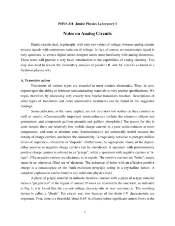
Chip MicrophotographB. Murmann andB. E. Boser,“A 12 b 75Msample/sPipelined ADCUsing OpenLoop ResidueAmplification,”ISSCC 2003.B. E. BoserEE240B – Layout8
Floor Planning Plan overall structure before laying out cells– Pin locations Power and ground Keep sensitive inputs away from other signals, clocks– Area estimates– Organization Cell placements Power distribution Wiring channels– Choice of package Size Length, orientation and inductance of bond-wires Common mistake– Great job laying out lots of small cells– Big mess connecting themB. E. BoserEE240B – Layout9
PCB Layout Power distribution––––DecouplingSupplyGround planesMany good references, e.g. Maxim Tutorial 5450: Successful PCB Grounding with Mixed-SignalChips - Follow the Path of Least ml Interconnects to other chips Co-design evaluation board with ASICB. E. BoserEE240B – Layout10
On-Chip Power RoutingGregorian & Temes, p. 515Which is preferable?B. E. BoserEE240B – Layout11
Supply Noise Typical sources– Digital logic– Clocks– IO pads Preventive measures––––Isolate in space & timeOn-chip decouplingLVDS I/OAvoid oversizing digital buffers Exacerbates supply noiseB. E. BoserEE240B – Layout12
Decoupling l?articleID 192200561B. E. BoserEE240B – Layout13
LVDS Outputs Well defined current returnpath 2 pins per signalRef: ADI application note 586B. E. BoserEE240B – Layout14
Reference Distribution Typically use single band-gap for entire chip How distribute to cells?a) Bias voltageb) CurrentB. E. BoserEE240B – Layout15
IR Drops Metal sheet resistance:50 100 mW/ 10 à 1W or 1mV/mA Use large V*– Costs headroom– Know most importantconstraint: dynamic rangeor matching?B. E. BoserEE240B – Layout16
Advanced Analog Integrated CircuitsComponentsBernhard E. BoserUniversity of California, Berkeleyboser@eecs.berkeley.eduCopyright 2016 by Bernhard BoserB. E. BoserEE240B – Layout17
“Parasitics” (sample values)LayerValueTC ppm/KVC ppm/VResistancen diff (no salicide)50 W/ 600200p diff (no salicide)80 W/ 600200n-well2 kW/ 40008,000poly (no salicide)30 W/ 500100poly (salicide)7 W/ 20050metal 1-480 mW/ metal 520 mW/ Capacitanceneighboring metalsB. E. Boser0.8 fF/µm2EE240B – Layout18
Advanced Analog Integrated CircuitsMatchingBernhard E. BoserUniversity of California, Berkeleyboser@eecs.berkeley.eduCopyright 2016 by Bernhard BoserB. E. BoserEE240B – Layout19
Layout for Matching1. Unit elements–E.g. equal W and L (use arrays for ratios)2. Large area–––Reduces random variationsBut more susceptible to gradientsBeware of increased parasitics Is speed or matching more important?E.g. RF versus ADC3. Defensive biasing––Voltage matching (differential pair): low V*, long LCurrent matching (mirror): large V*, same VDSB. E. BoserEE240B – Layout20
Layout for Matching (cont.)4. Same orientation––MOSFETs are nominally symmetricalActual devices are not Si is not isotropicImplants are not exactly isotropictranslational symmetrymirror symmetryWhich is better?B. E. BoserEE240B – Layout21
Layout for Matching (cont.)5. Compact layout–––Minimize temperature and stress variationsTradeoff with random variationsAvoid large aspect ratios E.g. W/L 180µm/180nmUse fingers à square layout6. Same vicinity–––Use dummy elements at edge of arrayProtects from process non-uniformity, e.g. etch rateMatch all layers (including metal)[ Su and Murmann ]B. E. BoserEE240B – Layout22
Layout for Matching (cont.)7. Stress and proximity effects–Package stress –Place devices in areas of low stress (typically center of die)At odds with mixed-signal floor plansLocal Mostly caused by metalAvoid routing M1 across active area8. Junctions– Keep junction edges (e.g. well) away from transistors (except S/D) At least 2x junction depth– Just because DRC rules permit it, minimum spacing is not alwaysbest B. E. BoserNot all spaces are critical for overall die sizeEE240B – Layout23
Layout for Matching (cont.)9. Oxide thickness––Devices with thinner oxide usually exhibit less mismatchUse minimum oxide thickness, if choice (low voltage devices)10. Temperature gradients–Sources of power dissipation ( 50mV) result in local heating–"# %"&––Keep matched devices away from hot spotsBeware of “Temperature memory effect” (thermal t usually 1/fs) 2 mV K11. Common centroid layout–See following slidesB. E. BoserEE240B – Layout24
Process Gradients Parameter variationsacross wafer(e.g.) direction of increasing Vth Typically small, wellapproximated by lineargradient, at least fordevices in close proximity Caused by processingartefacts, e.g. etchantconcentration higher nearthe edgeB. E. BoserEE240B – Layout25
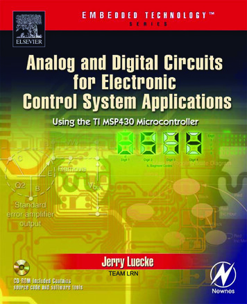
Example: Diff Pair Common Centroid Layout Linear gradients“average out” incommon-centroid layout 𝑉&0B. E. Boser 𝑉&0EE240B – Layout26
Common Centroid Layout 1 Lots of possibilities 𝑉&0 𝑉&0 “Common-centroid” in horizontaland vertical direction, should bedouble good? Not really:– Imbalanced wiring aroundtransistors– Mismatched gate parasitics– G24 overlaps source, G13 does notRef: M. Pelgrom et al, “A designer’s view on mismatch,” Chapter 13 in Nyquist A/DConverters, Sensors, and Robustness, Springer 2012, pp. 245-67.B. E. BoserEE240B – Layout27
Common Centroid Layout 2 A better option Asymmetry at the drains 𝑉&0 𝑉&0– pull D13 farther away from G24? Beware of what is to the left andright– place dummies as neededRef: M. Pelgrom et al, “A designer’s view onmismatch,” Chapter 13 in Nyquist A/DConverters, Sensors, and Robustness,Springer 2012, pp. 245-67.B. E. BoserEE240B – Layout28
Common Centroid Layout Principles1.Coincidence:–2.Center of all matched devices coincideSymmetry:––3.X- and Y-axisR’s and C’s exhibit 1-axis symmetryDispersion:––High dispersion reduces sensitivity to higher order (nonlinear) gradientsE.g. B. E. BoserABBAABBA: 2 runs (ABBA) of 2 segments (AB, BA)ABABBABA: 1 run of 2 segments (AB, BA)à ABABBABA has higher dispersion (preferable)EE240B – Layout29
Common Centroid Layout Principles (cont.)4. Compactness:– Approximately square layout– 2D patterns Better approximation of square layout Usually higher dispersion possible, DASBDBSADDBSADASBD5. Orientation:– Stress induced mobility variations: several percent error– Tilted wafers: 5% errorB. E. BoserEE240B – Layout30
Advanced Analog Integrated CircuitsInterferenceBernhard E. BoserUniversity of California, Berkeleyboser@eecs.berkeley.eduCopyright 2016 by Bernhard BoserB. E. BoserEE240B – Layout31
Coupling Mechanisms Interconnects– Mostly capacitive– Mitigation: Distance Shielding (constant potential in-between, e.g. supply or fixed control) Isolation in time (sample at “quiet” moment) Package– Bondwires Supply SubstrateB. E. BoserEE240B – Layout32
Package (Mutual) inductance 𝑉 "4 "5– Beware of fast transients– Test at low temperature (and fast corner wafers) Measures:– Differential circuits (LVDS IO)– Orthogonal bondwires– Choose package and pad layout that minimizes length of criticalbond wires (supplies and fast signals)B. E. BoserEE240B – Layout33
Power Supply Separate zones Regulator– Beware: low output impedance only at low frequencies! Decoupling capacitors– Key: low impedance (to load) Close Low area return path– Choose full equivalent model in simulations– Fast and right size is better than big and slowB. E. BoserEE240B – Layout34
Capacitive Coupling - Bias[ Murmann ]B. E. BoserEE240B – Layout35
Capacitive Coupling – SC Circuit[ Murmann ]B. E. BoserEE240B – Layout36
Substrate TypesB. E. BoserEE240B – Layout37
Epitaxial SubstrateNote:Lack of backsidewafer contactsubstantiallyincreases coupling!D. K. Su, M. J. Loinaz, S. Masui, and B. A. Wooley, "Experimental results and modeling techniques for substratenoise in mixed-signal integrated circuits," IEEE Journal of Solid-State Circuits, vol. 28, pp. 420 - 430, April 1993.B. E. BoserEE240B – Layout38
WaveformsB. E. BoserEE240B – Layout39
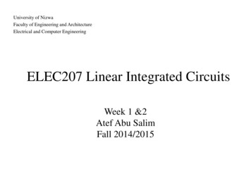
Current flow in Epi-Substrate Majority of currentflows in low-resistivitywafer Coupling is veryweak function ofdistanceB. E. BoserEE240B – Layout40
Cross-Talk versus DistanceB. E. BoserEE240B – Layout41
Guard RingsNot much effectLarge guardrings increasecoupling!Epi substrateB. E. BoserEE240B – Layout42
Model for Guard RingShared guard ring contactreduces isolation!B. E. BoserEE240B – Layout43
Backside ContactB. E. BoserEE240B – Layout44
Noise versus Backside Contact InductanceB. E. BoserEE240B – Layout45
Summary for Epi-Substrate Substrate closely modeled by ”single equipotential node” Most effective approach to minimize coupling”– Low resistance and inductance backside contact Guard rings– Limited effect– Beware of “telephone effect” Use dedicated guard ring potentialB. E. BoserEE240B – Layout46
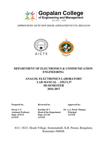
Current in High Resistivity SubstrateStrongly affected bysurface potentialSuggests guard ringshould be effectiveB. E. BoserEE240B – Layout47
Guard RingsB. E. BoserEE240B – Layout48
l?articleID 192200561B. E. BoserEE240B – Layout49
Deep ?articleID 192200561B. E. BoserEE240B – Layout50
Summary for Lightly Doped Substrate Distance and guard rings reduce coupling significantly But beware of injecting noise through guard ringsB. E. BoserEE240B – Layout51
Selected References R. Gharpurey and R. G. Meyer, "Modeling and analysis of substrate coupling inintegrated circuits," IEEE Journal of Solid-State Circuits, vol. 31, pp. 344 - 353, March1996. Balsha R. Stanisic, Nishath Verghese, Rob A. Rutenbar, L. Richard Carley, David J.Allstot; Addressing substrate coupling in mixed-mode ICs: Simulation and powerdistribution synthesis, IEEE Journal of Solid-State Circuits, vol. 29, pp. 226 - 238,March 1994. Kuntal Joardar; A simple approach to modeling cross-talk in integrated circuits, IEEEJournal of Solid-State Circuits, vol. 29, pp. 1212 - 1219, October 1994. Nishath Verghese, David J. Allstot; Computer-aided design considerations for mixedsignal coupling in RF integrated circuits, IEEE Journal of Solid-State Circuits, vol. 33,pp. 314 - 323, March 1998. A. Samavedam, A. Sadate, K. Mayaram, and T. S. Fiez, "A scalable substrate noisecoupling model for design of mixed-signal IC's," IEEE Journal of Solid-State Circuits,vol. 35, pp. 895 - 904, June 2000. Tallis Blalack et al., “On-Chip RF-Isolation le.jhtml?articleID 192200561B. E. BoserEE240B – Layout52
signal coupling in RF integrated circuits, IEEE Journal of Solid-State Circuits, vol. 33, pp. 314 -323, March 1998. A. Samavedam, A. Sadate, K. Mayaram, and T. S. Fiez, "A scalable substrate noise coupling model for design of mixed-signal IC's