Transcription
INSTRUCTION MANUALREFLECTORLESS TOTAL STATIONCYGNUS71013 90010
FOREWORDThank you for purchasing the Reflectorless Total Station, CYGNUS.For the best performance of the instruments, please carefully read these instructionsand keep them in a convenient location for future reference.1
General Handling PrecautionsBefore starting work or operation, be sure to check that the instrument isfunctioning correctly with normal performance.Do not submerge the instrument into water.The instrument can not be submerged underwater.The instrument is designed based on the International Standard IP54, therefore it isprotected from the splashing water.Setting the instrument on a tripodWhen mounting the instrument on a tripod, use a wooden tripod when possible. Thevibrations that may occur when using a metallic tripod can effect the measuring precision.Installing the tribrachIf the tribrach is installed incorrectly, the measuring precision could be effected.Occasionally check the adjusting screws on the tribrach. Make sure the base fixing lever islocked and the base fixing screws are tightened.Guarding the instrument against shocksWhen transporting the instrument, provide some protection to minimize risk of shocks.Heavy shocks may cause the measurement to be faulty.Carrying the instrumentAlways carry the instrument by its handgrip.Exposing the instrument to extreme heat.Do not leave the instrument in extreme heat for longer than necessary. It could adverselyaffect its performance.Sudden changes of temperatureAny sudden change of temperature to the instrument or prism may result in a reduction ofmeasuring distance range, i.e when taking the instrument out from a heated vehicle. Letinstrument acclimate itself to ambient temperature.Battery level checkConfirm battery level remaining before operating.Do not hold the lower part of display unitWhen you take out the instrument from a carrying case, or keep into the case, please holdthe hand grip and base of the instrument. Please do not hold the lower part of the displayunit.External power sourceUse only recommended batteries. Use of batteries not recommended by us may result inequipment failure.(For further information see the chapter 'BATTERY SYSTEM.')2
Display for Safe UseIn order to encourage the safe use of products and prevent any danger to the operator andothers or damage to properties, important warnings are put on the products and inserted in theinstruction manuals.We suggest that everyone understand the meaning of the following displays and icons beforereading the “Safety Cautions” and text.DisplayWARNINGCAUTIONMeaningIgnoring or disregard of this display may lead to the danger of death orserious injury.Ignoring or disregard of this display may lead to personal injury or physical damage. Injury refers to hurt, burn, electric shock, etc. Physical damage refers to extensive damage to buildings or equipment and furniture.Safety CautionsWARNING There is a risk of fire, electric shock or physical harm if you attempt to disassemble or repairthe instrument yourself.This is only to be carried out by an authorized dealer, only! Cause eye injury or blindness.Do not look at the sun through a telescope. High temperature may cause fire.Do not cover the charger while it is charging. Risk of fire or electric shock.Do not use damaged power cable, plug and socket. Risk of fire or electric shock.Do not use a wet battery or charger. May ignite explosively.Do not use the unit in areas exposed to high amounts of dust or ash, in areas where there is inadequate ventilation,or near combustible materials. An explosion could occur. Battery can cause explosion or injury.Do not dispose in fire or heat. Risk of fire or electric shock.Do not use any power voltage except the one given on manufacturers instructions. Battery can cause outbreak of fire.Do not use any other type of charger other than the one specified. Risk of fire or electric shock.Do not use an AC cable incompatible with the power supply voltage in use. The short circuit of a battery can cause a fire.Do not short circuit battery when storing it.3
CAUTION Use of controls or adjustment or performance of procedures other than those specified herein may result in hazardous radiation exposure. Do not connect or disconnect equipment with wet hands, you are at risk of electric shocks if you do! Risk of injury by overturn the carrying case.Do not stand or sit on the carrying cases. Please note that the tips of tripod can be hazardous, be aware of this when setting up or carrying the tripod. Risk of injury by falling down the instrument or case.Do not use a carrying case with a damaged grips or latches. Do not allow skin or clothing to come into contact with acid from the batteries, if this does occur then wash off withcopious amounts of water and seek medical advice. A plumb bob can cause an injury to a person if used incorrectly. It could be dangerous if the instrument falls over, please ensure you attach a hand grip to the instrument securely. Ensure that you mount the Tribrach correctly, failing to do so may result in injury if the tribrach were to fall over. It could be dangerous if the instrument falls over, please check that you fix the instrument to the tripod correctly. Risk of injury by falling down a tripod and an instrument.Always check that the screws of tripod are tightened. The battery is to be disposed of safely. The appliance is not intended for use by young children or infirm persons without supervision.Young children should be supervised to ensure that they do not play with the appliance.4
User1)This product is for professional use only!The user is required to be a qualified surveyor or have a good knowledge of surveying, in order tounderstand the user and safety instructions, before operating, inspecting or adjusting.2)Wear the required protectors (safety shoes, helmet, etc.) when operating.Exceptions from Responsibility1)The user of this product is expected to follow all operating instructions and make periodic checks of theproduct’s performance.2)The manufacturer, or its representatives, assumes no responsibility for results of a faulty or intentionalusage or misuse including any direct, indirect, consequential damage, and loss of profits.3)The manufacturer, or its representatives, assumes no responsibility for consequential damage, andloss of profits by any disaster, (an earthquake, storms, floods etc.).A fire, accident, or an act of a third party and/or a usage any other usual conditions.4)The manufacturer, or its representatives, assumes no responsibility for any damage, and loss of profitsdue to a change of data, loss of data, an interruption of business etc., caused by using the product oran unusable product.5)The manufacturer, or its representatives, assumes no responsibility for any damage, and loss of profitscaused by usage except for explained in the user manual.6)The manufacturer, or its representatives, assumes no responsibility for damage caused by wrongmovement, or action due to connecting with other products.5
Laser SafetyCYGNUS is classified as the following class of Laser Product according to IEC Standard Publication60825-1 Ed.2.0: 2007 and United States Government Code of Federal Regulation FDA CDRH 21CFRPart 1040.10 and 1040.11 (Complies with FDA performance standards for laser products except fordeviations pursuant to Laser Notice No.50, dated June 24, 2007.)z EDM device in objective lens:z When using prism:Class 3R Laser ProductClass 2 Laser ProductEDM device is classified as Class 3R Laser Product when reflectorless measurement is selected.When the prism is selected as target, the output is equivalent to the safer class 2.CWARNINGz Use of controls or adjustments or performance of procedures other than those specified herein mayresult in hazardous radiation exposure.z Follow the safety instructions on the labels attached to the instrument as well as in this manual toensure safe use of this laser product. ࠩశߩ ญAVOID EXPOSURE-Laser radiationis emitted from this aperture.Laser beamemittedfrom here ࠩశ ߳ߩ ធⵍ߫ߊࠍㆱߌࠆߎߣ/#: O9 .& POࠢ ࠬ 4 ࠩ ຠ, 5 % LASER RADIATIONAVOID DIRECT EYE EXPOSUREMAX 5mW LD 625-695nmCLASS3R LASER PRODUCTIEC 60825-1 Ed. 2.0 : 2007z Never point the laser beam at another person. If the laser beam strikes skin or an eye, it couldcause serious injury.z Do not look directly into the laser beam source. Doing so could cause permanent eye damage.z Do not stare at the laser beam. Doing so could cause permanent eye damage.z If an eye injury is caused by exposure to the laser beam, seek immediate medical attention from alicensed ophthalmologist.z Never look at the laser beam through a telescope, binoculars or other optical instruments. Doing socould cause permanent eye damage.z Sight the targets so that laser beam does not stray from them.CCAUTIONz Perform checks at start of work and periodic checks and adjustments with the laser beam emittedunder normal conditions.z When the instrument is not being used, turn off the power.z When disposing of the instrument, destroy the battery connector so that the laser beam cannot beemitted.z Operate the instrument with due caution to avoid injuries that may be caused by the laser beamunintentionally striking a person in the eye. Avoid setting the instrument at heights at which the pathof the laser beam may strike pedestrians or drivers at head height.z Never point the laser beam at mirrors, windows or surfaces that are highly reflective. The reflectedlaser beam could cause serious injury.6
z When using the Laser-pointer function, be sure to turn OFF the output laser after distancemeasurement is completed. Even if distance measurement is canceled, the Laser-pointer functionis still operating and the laser beam continues to be emitted.z Only those who have been received training as per the following items shall use this product.z Read the Instruction manual for usage procedures for this product.z Hazardous protection procedures. (read "Laser Safety")z Requisite protective gear. (read "Laser Safety")z Accident reporting procedures (stipulate procedures beforehand for transporting the injured andcontacting physicians in case there are laser induced injuries).z Persons working within the range of the laser beam are advised to wear eye protection whichcorresponds to the laser wavelength of the instrument being used.z Areas in which the lasers are used should be posted with laser warning notices.Symbol mark while the laser is emitting.The following symbol mark will appear at theright side of the second line.TILT SENSOR:[XY-ON]X:-0 00'25"Y: 0 00'20"X-ON XY-ON OFF L.PL7Symbol mark
ContentsFOREWORD . . . . . . . . . . . . . . . . . . . . . . . . . . . . . . . . . . . . . . . . . . . . . . . . . . 1General Handling Precautions. . . . . . . . . . . . . . . . . . . . . . . . . . . . . . . . . . . . . . . . . . . . . . . .2Display for Safe Use . . . . . . . . . . . . . . . . . . . . . . . . . . . . . . . . . . . . . . . . . . . . . . . . . . . . . . .3Safety Cautions . . . . . . . . . . . . . . . . . . . . . . . . . . . . . . . . . . . . . . . . . . . . . . . . . . . . . . . . . . . .3User . . . . . . . . . . . . . . . . . . . . . . . . . . . . . . . . . . . . . . . . . . . . . . . . . . . . . . . . . . . . . . . . . . . . .5Exceptions from Responsibility . . . . . . . . . . . . . . . . . . . . . . . . . . . . . . . . . . . . . . . . . . . . . . . .5Laser Safety. . . . . . . . . . . . . . . . . . . . . . . . . . . . . . . . . . . . . . . . . . . . . . . . . . . . . . . . . . . . . . .6Symbol mark while the laser is emitting. . . . . . . . . . . . . . . . . . . . . . . . . . . . . . . . . . . . . . . . . .7Standard Set Composition. . . . . . . . . . . . . . . . . . . . . . . . . . . . . . . . . . . . . . . . . . . . . . . . . . .111 NOMENCLATURE AND FUNCTIONS . . . . . . . . . . . . . . . . . . . . . . . . . . . 1-11.11.21.31.41.51.6Nomenclature . . . . . . . . . . . . . . . . . . . . . . . . . . . . . . . . . . . . . . . . . . . . . . . . . . . . . . . . 1-1Display . . . . . . . . . . . . . . . . . . . . . . . . . . . . . . . . . . . . . . . . . . . . . . . . . . . . . . . . . . . . . 1-3Operating Key. . . . . . . . . . . . . . . . . . . . . . . . . . . . . . . . . . . . . . . . . . . . . . . . . . . . . . . . 1-4Function Key (Soft Key) . . . . . . . . . . . . . . . . . . . . . . . . . . . . . . . . . . . . . . . . . . . . . . . . 1-5Star key mode. . . . . . . . . . . . . . . . . . . . . . . . . . . . . . . . . . . . . . . . . . . . . . . . . . . . . . . . 1-7Serial signal RS-232C connector . . . . . . . . . . . . . . . . . . . . . . . . . . . . . . . . . . . . . . . . . 1-92 PREPARATION FOR MEASUREMENT . . . . . . . . . . . . . . . . . . . . . . . . . . 2-12.12.22.32.42.5Setting Instrument Up For Measurement . . . . . . . . . . . . . . . . . . . . . . . . . . . . . . . . . . . 2-1Power Switch Key ON . . . . . . . . . . . . . . . . . . . . . . . . . . . . . . . . . . . . . . . . . . . . . . . . . 2-2Battery Power Remaining Display . . . . . . . . . . . . . . . . . . . . . . . . . . . . . . . . . . . . . . . . 2-3Vertical Angle Tilt Correction . . . . . . . . . . . . . . . . . . . . . . . . . . . . . . . . . . . . . . . . . . . . 2-4How to Enter Alphanumeric characters . . . . . . . . . . . . . . . . . . . . . . . . . . . . . . . . . . . . 2-62.5.1 How to Enter Alphanumeric Characters. . . . . . . . . . . . . . . . . . . . . . . . . . . . . . . . 2-63 ANGLE MEASUREMENT . . . . . . . . . . . . . . . . . . . . . . . . . . . . . . . . . . . . . 3-13.1 Measuring Horizontal Angle Right and Vertical Angle . . . . . . . . . . . . . . . . . . . . . . . . . 3-13.2 Switching Horizontal Angle Right/Left. . . . . . . . . . . . . . . . . . . . . . . . . . . . . . . . . . . . . . 3-23.3 Measuring from the Required Horizontal Angle . . . . . . . . . . . . . . . . . . . . . . . . . . . . . . 3-23.3.1 Setting by Holding the Angle . . . . . . . . . . . . . . . . . . . . . . . . . . . . . . . . . . . . . . . . 3-23.3.2 Setting a Horizontal Angle from the Keys . . . . . . . . . . . . . . . . . . . . . . . . . . . . . . 3-33.4 Vertical Angle Percent Grade(%) Mode . . . . . . . . . . . . . . . . . . . . . . . . . . . . . . . . . . . . 3-33.5 Repetition Angle Measurement . . . . . . . . . . . . . . . . . . . . . . . . . . . . . . . . . . . . . . . . . . 3-43.6 Buzzer Sounding for Horizontal Angle 90 Increments . . . . . . . . . . . . . . . . . . . . . . . . 3-53.7 Compasses (vertical angle) . . . . . . . . . . . . . . . . . . . . . . . . . . . . . . . . . . . . . . . . . . . . . 3-64 DISTANCE MEASUREMENT . . . . . . . . . . . . . . . . . . . . . . . . . . . . . . . . . . 4-14.14.24.34.44.54.64.7Setting of the Atmospheric Correction . . . . . . . . . . . . . . . . . . . . . . . . . . . . . . . . . . . . . 4-1Setting of the Correction for Prism Constant / Non-prism Constant . . . . . . . . . . . . . . . 4-1Distance Measurement (Continuous Measurement) . . . . . . . . . . . . . . . . . . . . . . . . . . 4-2Distance Measurement (N-time Measurement/Single Measurement) . . . . . . . . . . . . . 4-3Fine Mode/Tracking Mode/Coarse Mode . . . . . . . . . . . . . . . . . . . . . . . . . . . . . . . . . . . 4-4Stake Out (S.O) . . . . . . . . . . . . . . . . . . . . . . . . . . . . . . . . . . . . . . . . . . . . . . . . . . . . . . 4-5Offset Measurement . . . . . . . . . . . . . . . . . . . . . . . . . . . . . . . . . . . . . . . . . . . . . . . . . . . 4-64.7.1 Angle Offset . . . . . . . . . . . . . . . . . . . . . . . . . . . . . . . . . . . . . . . . . . . . . . . . . . . . . 4-74.7.2 Distance Offset Measurement . . . . . . . . . . . . . . . . . . . . . . . . . . . . . . . . . . . . . . . 4-94.7.3 Plane Offset Measurement . . . . . . . . . . . . . . . . . . . . . . . . . . . . . . . . . . . . . . . . 4-114.7.4 Column Offset Measurement . . . . . . . . . . . . . . . . . . . . . . . . . . . . . . . . . . . . . . . 4-135 COORDINATE MEASUREMENT . . . . . . . . . . . . . . . . . . . . . . . . . . . . . . . 5-15.15.25.35.4Setting Coordinate Values of Occupied Point. . . . . . . . . . . . . . . . . . . . . . . . . . . . . . . . 5-1Setting Height of the Instrument . . . . . . . . . . . . . . . . . . . . . . . . . . . . . . . . . . . . . . . . . . 5-2Setting Height of Target (Prism Height) . . . . . . . . . . . . . . . . . . . . . . . . . . . . . . . . . . . . 5-2Execution of Coordinate Measuring . . . . . . . . . . . . . . . . . . . . . . . . . . . . . . . . . . . . . . . 5-36 SPECIAL MODE (Menu Mode). . . . . . . . . . . . . . . . . . . . . . . . . . . . . . . . . 6-16.1 Application Measurement (PROGRAMS) . . . . . . . . . . . . . . . . . . . . . . . . . . . . . . . . . . 6-26.1.1 Remote Elevation measurement (REM) . . . . . . . . . . . . . . . . . . . . . . . . . . . . . . . 6-26.1.2 Missing Line Measurement (MLM). . . . . . . . . . . . . . . . . . . . . . . . . . . . . . . . . . . . 6-56.1.3 Setting Z Coordinate of Occupied Point. . . . . . . . . . . . . . . . . . . . . . . . . . . . . . . . 6-86.1.4 Area Calculation. . . . . . . . . . . . . . . . . . . . . . . . . . . . . . . . . . . . . . . . . . . . . . . . . 6-116.1.5 Point to Line Measurement . . . . . . . . . . . . . . . . . . . . . . . . . . . . . . . . . . . . . . . . 6-146.2 Setting the GRID FACTOR. . . . . . . . . . . . . . . . . . . . . . . . . . . . . . . . . . . . . . . . . . . . . 6-166.3 Setting Illumination of Display . . . . . . . . . . . . . . . . . . . . . . . . . . . . . . . . . . . . . . . . . . 6-176.4 Setting Mode 1 . . . . . . . . . . . . . . . . . . . . . . . . . . . . . . . . . . . . . . . . . . . . . . . . . . . . . . 6-188
6.4.1 Setting Minimum Reading . . . . . . . . . . . . . . . . . . . . . . . . . . . . . . . . . . . . . . . . . 6-186.4.2 Auto Power Off. . . . . . . . . . . . . . . . . . . . . . . . . . . . . . . . . . . . . . . . . . . . . . . . . . 6-196.4.3 Vertical Angle Tilt correction (Tilt ON/OFF) . . . . . . . . . . . . . . . . . . . . . . . . . . . . 6-206.4.4 Setting RS-232C communication with external device . . . . . . . . . . . . . . . . . . . 6-216.5 Setting Contrast of Display . . . . . . . . . . . . . . . . . . . . . . . . . . . . . . . . . . . . . . . . . . . . 6-226.6 ROAD . . . . . . . . . . . . . . . . . . . . . . . . . . . . . . . . . . . . . . . . . . . . . . . . . . . . . . . . . . . . . 6-236.6.1 Input Start Point . . . . . . . . . . . . . . . . . . . . . . . . . . . . . . . . . . . . . . . . . . . . . . . . . 6-246.6.2 Input Road Data. . . . . . . . . . . . . . . . . . . . . . . . . . . . . . . . . . . . . . . . . . . . . . . . . 6-256.6.3 Search Data . . . . . . . . . . . . . . . . . . . . . . . . . . . . . . . . . . . . . . . . . . . . . . . . . . . . 6-296.6.4 Edit Data . . . . . . . . . . . . . . . . . . . . . . . . . . . . . . . . . . . . . . . . . . . . . . . . . . . . . . 6-296.6.5 Set OCC and BS . . . . . . . . . . . . . . . . . . . . . . . . . . . . . . . . . . . . . . . . . . . . . . . . 6-306.6.6 Setout Road . . . . . . . . . . . . . . . . . . . . . . . . . . . . . . . . . . . . . . . . . . . . . . . . . . . . 6-326.6.7 Select a File . . . . . . . . . . . . . . . . . . . . . . . . . . . . . . . . . . . . . . . . . . . . . . . . . . . . 6-336.6.8 Initialize ROAD data. . . . . . . . . . . . . . . . . . . . . . . . . . . . . . . . . . . . . . . . . . . . . . 6-337 DATA COLLECTION. . . . . . . . . . . . . . . . . . . . . . . . . . . . . . . . . . . . . . . . . 7-17.1 Preparation . . . . . . . . . . . . . . . . . . . . . . . . . . . . . . . . . . . . . . . . . . . . . . . . . . . . . . . . . . 7-37.1.1 Selecting a File for Data Collection . . . . . . . . . . . . . . . . . . . . . . . . . . . . . . . . . . . 7-37.1.2 Selecting a Coordinate File for Data Collection . . . . . . . . . . . . . . . . . . . . . . . . . . 7-47.1.3 Occupied Point and Backsight Point . . . . . . . . . . . . . . . . . . . . . . . . . . . . . . . . . . 7-47.2 Operational Procedure of DATA COLLECT . . . . . . . . . . . . . . . . . . . . . . . . . . . . . . . . . 7-77.2.1 Searching the recorded data . . . . . . . . . . . . . . . . . . . . . . . . . . . . . . . . . . . . . . . . 7-87.2.2 Entering PCODE / ID using PCODE Library . . . . . . . . . . . . . . . . . . . . . . . . . . . . 7-87.2.3 Entering PCODE / ID from the list of PCODE . . . . . . . . . . . . . . . . . . . . . . . . . . . 7-97.3 Data Collect Offset Measurement mode. . . . . . . . . . . . . . . . . . . . . . . . . . . . . . . . . . . 7-107.3.1 Angle Offset Measurement . . . . . . . . . . . . . . . . . . . . . . . . . . . . . . . . . . . . . . . . 7-107.3.2 Distance Offset Measurement . . . . . . . . . . . . . . . . . . . . . . . . . . . . . . . . . . . . . . 7-127.3.3 Plane Offset Measurement . . . . . . . . . . . . . . . . . . . . . . . . . . . . . . . . . . . . . . . . 7-147.3.4 Column Offset Measurement . . . . . . . . . . . . . . . . . . . . . . . . . . . . . . . . . . . . . . . 7-167.4 NEZ Auto Calculation . . . . . . . . . . . . . . . . . . . . . . . . . . . . . . . . . . . . . . . . . . . . . . . . . 7-177.5 Point to Line Measurement. . . . . . . . . . . . . . . . . . . . . . . . . . . . . . . . . . . . . . . . . . . . . 7-187.5.1 To change to the point to line measurement . . . . . . . . . . . . . . . . . . . . . . . . . . . 7-187.5.2 Executing a point to line measurement . . . . . . . . . . . . . . . . . . . . . . . . . . . . . . . 7-197.6 Editing PCODE Library [PCODE INPUT] . . . . . . . . . . . . . . . . . . . . . . . . . . . . . . . . . . 7-207.7 Setting Parameter of Data Collect [CONFIG.] . . . . . . . . . . . . . . . . . . . . . . . . . . . . . . 7-218 LAYOUT . . . . . . . . . . . . . . . . . . . . . . . . . . . . . . . . . . . . . . . . . . . . . . . . . . 8-18.1 Preparation . . . . . . . . . . . . . . . . . . . . . . . . . . . . . . . . . . . . . . . . . . . . . . . . . . . . . . . . . . 8-38.1.1 Setting the GRID FACTOR . . . . . . . . . . . . . . . . . . . . . . . . . . . . . . . . . . . . . . . . . 8-38.1.2 Selecting Coordinate Data File . . . . . . . . . . . . . . . . . . . . . . . . . . . . . . . . . . . . . . 8-48.1.3 Setting Occupied Point . . . . . . . . . . . . . . . . . . . . . . . . . . . . . . . . . . . . . . . . . . . . 8-58.1.4 Setting Backsight Point . . . . . . . . . . . . . . . . . . . . . . . . . . . . . . . . . . . . . . . . . . . . 8-78.2 Executing a Layout . . . . . . . . . . . . . . . . . . . . . . . . . . . . . . . . . . . . . . . . . . . . . . . . . . . . 8-98.2.1 Layout of Coordinates of Point to Line . . . . . . . . . . . . . . . . . . . . . . . . . . . . . . . . 8-118.3 Setting a New Point . . . . . . . . . . . . . . . . . . . . . . . . . . . . . . . . . . . . . . . . . . . . . . . . . . 8-128.3.1 Side Shot Method . . . . . . . . . . . . . . . . . . . . . . . . . . . . . . . . . . . . . . . . . . . . . . . 8-128.3.2 Resection Method . . . . . . . . . . . . . . . . . . . . . . . . . . . . . . . . . . . . . . . . . . . . . . . 8-149 MEMORY MANAGER MODE . . . . . . . . . . . . . . . . . . . . . . . . . . . . . . . . . . 9-19.1 Display Internal Memory Status . . . . . . . . . . . . . . . . . . . . . . . . . . . . . . . . . . . . . . . . . . 9-29.2 Searching Data . . . . . . . . . . . . . . . . . . . . . . . . . . . . . . . . . . . . . . . . . . . . . . . . . . . . . . . 9-39.2.1 Measured Data Searching . . . . . . . . . . . . . . . . . . . . . . . . . . . . . . . . . . . . . . . . . . 9-39.2.2 Coordinate Data Searching . . . . . . . . . . . . . . . . . . . . . . . . . . . . . . . . . . . . . . . . . 9-59.2.3 PCODE LIBRARY Searching. . . . . . . . . . . . . . . . . . . . . . . . . . . . . . . . . . . . . . . . 9-69.3 FILE MAINTENANCE . . . . . . . . . . . . . . . . . . . . . . . . . . . . . . . . . . . . . . . . . . . . . . . . . . 9-79.3.1 Rename a File . . . . . . . . . . . . . . . . . . . . . . . . . . . . . . . . . . . . . . . . . . . . . . . . . . . 9-89.3.2 Searching Data in a File. . . . . . . . . . . . . . . . . . . . . . . . . . . . . . . . . . . . . . . . . . . . 9-89.3.3 Deleting a File . . . . . . . . . . . . . . . . . . . . . . . . . . . . . . . . . . . . . . . . . . . . . . . . . . . 9-99.4 Coordinate Data Direct Key Input . . . . . . . . . . . . . . . . . . . . . . . . . . . . . . . . . . . . . . . . 9-109.4.1 Coordinate data input . . . . . . . . . . . . . . . . . . . . . . . . . . . . . . . . . . . . . . . . . . . . 9-109.4.2 PTL (Point to Line) data input . . . . . . . . . . . . . . . . . . . . . . . . . . . . . . . . . . . . . . 9-119.5 Delete a Coordinate Data from a File . . . . . . . . . . . . . . . . . . . . . . . . . . . . . . . . . . . . . 9-129.6 Editing PCODE Library . . . . . . . . . . . . . . . . . . . . . . . . . . . . . . . . . . . . . . . . . . . . . . . . 9-139.7 Data Communications . . . . . . . . . . . . . . . . . . . . . . . . . . . . . . . . . . . . . . . . . . . . . . . . 9-149.7.1 Sending Data . . . . . . . . . . . . . . . . . . . . . . . . . . . . . . . . . . . . . . . . . . . . . . . . . . . 9-149.7.2 Loading Data . . . . . . . . . . . . . . . . . . . . . . . . . . . . . . . . . . . . . . . . . . . . . . . . . . . 9-159
9.7.3 Setting Parameter of Data Communications . . . . . . . . . . . . . . . . . . . . . . . . . . . 9-169.8 Initialization . . . . . . . . . . . . . . . . . . . . . . . . . . . . . . . . . . . . . . . . . . . . . . . . . . . . . . . . . 9-1710 SET AUDIO MODE . . . . . . . . . . . . . . . . . . . . . . . . . . . . . . . . . . . . . . . . 10-111 SETTING THE PRISM / NON-PRISM CONSTANT VALUE . . . . . . . . . 11-112 SETTING ATMOSPHERIC CORRECTION. . . . . . . . . . . . . . . . . . . . . . 12-112.1 Calculation of Atmospheric Correction . . . . . . . . . . . . . . . . . . . . . . . . . . . . . . . . . . . 12-112.2 Setting of Atmospheric Correction Value . . . . . . . . . . . . . . . . . . . . . . . . . . . . . . . . . 12-113 CORRECTION FOR REFRACTION AND EARTH CURVATURE . . . . 13-113.1 Distance Calculation Formula. . . . . . . . . . . . . . . . . . . . . . . . . . . . . . . . . . . . . . . . . . 13-114 POWER SOURCE AND CHARGING . . . . . . . . . . . . . . . . . . . . . . . . . . 14-114.1 On-board Battery BT-77Q. . . . . . . . . . . . . . . . . . . . . . . . . . . . . . . . . . . . . . . . . . . . . 14-115 DETACH/ATTACH OF TRIBRACH. . . . . . . . . . . . . . . . . . . . . . . . . . . . 15-116 SELECTING MODE. . . . . . . . . . . . . . . . . . . . . . . . . . . . . . . . . . . . . . . . 16-116.1 Items of the Selecting Mode . . . . . . . . . . . . . . . . . . . . . . . . . . . . . . . . . . . . . . . . . . . 16-116.2 How to Set Selecting Mode . . . . . . . . . . . . . . . . . . . . . . . . . . . . . . . . . . . . . . . . . . . 16-317 CHECK AND ADJUSTMENT . . . . . . . . . . . . . . . . . . . . . . . . . . . . . . . . 17-117.1 Checking and adjusting of instrument constant . . . . . . . . . . . . . . . . . . . . . . . . . . . . 17-117.2 Checking the Optical Axis. . . . . . . . . . . . . . . . . . . . . . . . . . . . . . . . . . . . . . . . . . . . . 17-217.3 Checking/Adjusting the Theodolite Functions. . . . . . . . . . . . . . . . . . . . . . . . . . . . . . 17-317.3.1 Checking /Adjusting the Plate Level . . . . . . . . . . . . . . . . . . . . . . . . . . . . . . . . 17-417.3.2 Checking /Adjusting the Circular Level . . . . . . . . . . . . . . . . . . . . . . . . . . . . . . 17-417.3.3 Adjustment of the Vertical Cross-hair . . . . . . . . . . . . . . . . . . . . . . . . . . . . . . . 17-517.3.4 Collimation of the Instrument . . . . . . . . . . . . . . . . . . . . . . . . . . . . . . . . . . . . . . 17-617.3.5 Checking / Adjusting the Optical Plummet Telescope . . . . . . . . . . . . . . . . . . . 17-717.3.6 Adjustment of Vertical Angle 0 Datum . . . . . . . . . . . . . . . . . . . . . . . . . . . . . . . 17-817.4 How to Set the Instrument Constant Value. . . . . . . . . . . . . . . . . . . . . . . . . . . . . . . . 17-918 PRECAUTIONS . . . . . . . . . . . . . . . . . . . . . . . . . . . . . . . . . . . . . . . . . . . 18-119 SPECIAL ACCESSORIES . . . . . . . . . . . . . . . . . . . . . . . . . . . . . . . . . . 19-120 BATTERY SYSTEM . . . . . . . . . . . . . . . . . . . . . . . . . . . . . . . . . . . . . . . 20-121 PRISM SYSTEM . . . . . . . . . . . . . . . . . . . . . . . . . . . . . . . . . . . . . . . . . . 21-122 ERROR DISPLAYS . . . . . . . . . . . . . . . . . . . . . . . . . . . . . . . . . . . . . . . . 22-123 SPECIFICATIONS . . . . . . . . . . . . . . . . . . . . . . . . . . . . . . . . . . . . . . . . . 23-124 REGULATIONS . . . . . . . . . . . . . . . . . . . . . . . . . . . . . . . . . . . . . . . . . . . 24-1APPENDIX .Appendix-110
Standard Set CompositionThe numerical value in parentheses shows the quantity.CYGNUS (with lens cap) (1)Plastic carrying case(1)On-board Battery BT-77Q (1)Battery charger BC-L1W (1),Plastic rain cover(1)Tool kit (1)Instruction manual (1)Silicon cloth (1)(Make sure that all of the above items are with the instrument when purchased.)11
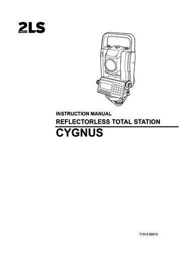
1 NOMENCLATURE AND FUNCTIONS1NOMENCLATURE AND FUNCTIONS1.1 NomenclatureHandgrip locking screwHandgripObjective lensLaser pointerLaser apertureInstrumentcenter markSerial SignalConnectorOptical plummettelescopeDisplay unitTribrach fixing leverCircular levelBaseAdjustment screwfor circular levelLeveling screw1-1
1 NOMENCLATURE AND FUNCTIONSSighting collimatorBattery locking buttonTelescope focusing knobTelescope gripOn-board batteryBT-77QTelescope eyepieceInstrumentcenter markVertical motion clampVertical tangent screwHorizontaltangent screwPlate levelHorizontalmotion clampDisplay unit1-2
1 NOMENCLATURE AND FUNCTIONS1.2 Displayz DisplayThe display uses a graphic LCD which has 4 lines and 20 characters per line. In general, the upperthree lines display measured data, and the bottom line displays the soft key function which changeswith the m
REFLECTORLESS TOTAL STATION INSTRUCTION MANUAL 71013 90010. 1 FOREWORD Thank you for purchasing the Reflectorless Total Station, CYGNUS. For the best performance of the instruments, please carefully read these instructions and k