Transcription
System Design Trade-Offs in a Next-GenerationEmbedded Wireless PlatformMichael P AndersenDavid E. CullerElectrical Engineering and Computer SciencesUniversity of California at BerkeleyTechnical Report No. /TechRpts/2014/EECS-2014-162.htmlAugust 25, 2014
Copyright 2014, by the author(s).All rights reserved.Permission to make digital or hard copies of all or part of this work forpersonal or classroom use is granted without fee provided that copies arenot made or distributed for profit or commercial advantage and thatcopies bear this notice and the full citation on the first page. To copyotherwise, to republish, to post on servers or to redistribute to lists,requires prior specific permission.
System Design Trade-Offs in a Next-Generation EmbeddedWireless PlatformMichael P AndersenDavid E. CullerDepartment of Computer ScienceUniversity of California, BerkeleyDepartment of Computer ScienceUniversity of California, eley.eduAbstract1Over the course of the past decade, the evolution of advanced low-energy microcontrollers has raised three questions which this paper outlines and addresses.The first question is: Can a 32-bit platform be constructedthat provides advanced features but fits within the energyconstraints of a wireless sensor network? We answer thisin the affirmative by presenting the design and preliminaryevaluation of Storm – one such system based on an ARMCortex-M4 that achieves 2.3µA idle current with a 1.5µSwake up time.The second question we answer is: Can this platformsimultaneously meet the very different demands of bothmonitoring-type applications and cyber-physical systems?We demonstrate that this is indeed possible and present thedesign trade-offs that must be made to achieve this, yieldinga module with a rich set of exported peripherals that fits in a16mm x 26mm form factor.The final question explored by this paper is: If such aplatform is possible, what new opportunities and challengeswould it hold for embedded operating systems? We answerthis by showing that the usage of modern 32 bit microcontrollers requires reconsidering system architecture governing power management, clock selection and inter-module dependencies, as well as offering opportunities for supervisorycode and the coordination of common tasks without CPU intervention.In the early years of wireless sensor network research,hardware platforms evolved rapidly and operating systemstructures were transformed by each new generation. From1999 until 2004, each release of a significant microcontrolleror radio advance was incorporated into a new open platform,including WeC [15], Rene [12], Mica [11], MicaZ, iMOTE,BTnode, EYES, iMOTE2 [16], Telos [17]. But since theconsolidation around 16 bit microcontrollers (MSP430, ATmega) and IEEE 15.4 radios (CC2410, RF231) a decade ago,new platforms have largely been variations in module formfactor, e.g., Epic, Shimmer, despite tremendous growth andadvance in essentially all aspects of the industrial ecosystemaround embedded networks, wearable technology, and cellular platforms. And, ever since the earliest generations a basic question was whether it was viable to utilize a full 32-bitprocessor, with adequate storage and the associated widelyavailable tool chains, while meeting a power profile that permitted lifetimes on the scale of battery shelf life and a smallpart count. The introduction of xSCALE and ARM microcontrollers brought down the part count and improved theactive power efficiency, but low power operation remainedan elusive challenge. System-on-a-chip options emerged,bringing the part count down further, but they had extremelylimited processor architectures and weak tool-chain capability. In this paper, we examine whether this situation has finally changed.In particular, we address three basic questions.1. Can we now utilize full-featured, 32-bit microcontrollers with enough memory and flash to support sophisticated applications with the power profile of amote, i.e., idle power of a few uWs, fast wake up, andefficient active operation?Categories and Subject DescriptorsB.0 [Hardware]: General; C.3 [Special-Purpose andApplication-Based Systems]General TermsDesign, PerformanceKeywordsWireless sensor networks, Energy efficiencyIntroduction2. Can the platform serve the distinct needs of the twodominant usage models: wireless monitoring, witha few sensors and predictable behavior and cyberphysical systems with rich I/O, actuation, and dynamicvariation?3. If so, does such a platform introduce qualitatively newoperating system challenges and opportunities?We show by developing a new platform around specificofferings in the Cortex-M family that the answer to the firsttwo questions is affirmative and by examining aspects of thissolution we outline a new suite of important system oppor-
tubities and challenges. Indeed, the building blocks are finally of a state where the integration into a system-on-a-chipis likely to produce extremely general, cost-effective solutions.Section 2 frames the investigation with an enumerationand characterization of the demands placed on a modernwireless embedded platform, forming the criteria for theevaluation of a next-generation mote. Section 3 discussescurrent trends in microprocessor, transceiver and SoC development, leading to a blueprint for a wireless embedded system that is representative of current trends in industry andmeets the demands of current and future wireless embeddednetworks.Addressing the first question requires not just an analysisof data sheets; a quantitative, empirical study of the complexities and implications of utilizing next-generation hardwarein sensor networks requires the careful design of a physical platform. Section 4 presents one such system – Storm– an example reference platform based upon best-in-classnext-generation components. The process of mapping themodel of a representative wireless embedded system into aphysical instantiation by evaluation of available componentsand selective design trade-offs is discussed. A physical module design is presented that extends and improves upon the3Ps [9] to serve the range of usage models from simple sensor networks for monitoring to sophisticated cyber-physicalsystems.The Storm platform is then used as a representative fornext-generation wireless platforms in general for an exploration of new systems opportunities and challenges in Section 6. We identify five primary factors – modular powermanagement, multiple clock domains, inter-module compatibility, chaining of multiple overlapping transfers and increased supervisory control – which lead to a whole-systemoptimization framework for real time embedded operatingsystems, such as TinyOS. Such intricacies naturally posenew problems for the architecture of any embedded operating system aiming to abstract device-specific complexityfrom users by utilizing layering and modularity.2Requirements of a modern wireless platformAs sensor networks have been utilized as solutions in agrowing number of fields – such as medicine [5], buildingmanagement [4] [10], energy usage awareness, security andecological studies [14] – the demands placed upon individualsensor nodes have become more sharply defined.2.1Microprocessor resourcesResource bound applications, such as point-of-origin dataanalysis or feature extraction, distributed computation, frequency domain techniques, and so on utilize advanced algorithms. However, even simple network stacks generallyfill most of available memory on traditional mote-class platforms. For example, Table 1 lists the program memory andRAM space requirements for some configurations of applications that currently ship with TinyOS [1].Basic applications, such as UDPEcho, barely fit in the48KB of program space afforded by the MSP430F1611, andTable 1: Requirements for TinyOS applications targetingTelosB with 90926752staticUDPEcho424006864dhcpPPPRouter FTBFS FTBFSsome applications such as the PPPRouter do not fit at all1 .It is clear that even for applications that are not uniquelylarge or complex, more program memory is required. Computational requirements vary widely, generally with bursts ofprocessing and long idle periods.2.2Peripheral requirementsIn addition to computational and storage resources, manyapplications place heavy demands on the peripherals of thenodes. This is particularly prevalent in cyber-physical systems where the mote may form the core of a much largersystem composed of several sensors and actuators, requiringmodules such as PWM controllers, external communicationinterfaces and high speed analog to digital converters. Someexamples of this include mobile medical devices[19] or embedded robotics[8].An interesting observation is that although many of thesecyber-physical systems require increased IO, they simultaneously require a small form factor [18]. This means that afully generic platform must be able to provide a rich set ofperipherals, while also remaining compact.2.3Energy budgetMany deeply embedded “deploy and forget” wireless sensor networks utilize battery powered nodes that aim to below cost and zero maintenance. The primary requirementimposed on the systems is that they must be capable of extremely low idle currents and low duty cycles. In addition,this category of research often focuses on larger deploymentsof cheaper sensors.Learning from prior platforms and their evaluation, suchas the TelosB [17], two primary characteristics influence theenergy efficiency of the system: the current in the processor’slowest useful power saving mode and the wake-up cost. Wequalify this with “useful” because many components providepower saving modes that, while impressive, are difficult touse except in specialized applications. The most commonare power saving modes where the contents of SRAM arenot retained, or where all clocks are stopped and no interrupts can occur. We define the lowest useful power mode asone where there is at least one timer running that is capable of waking the processor up to full running state at somepredetermined time in the future. This naturally leads to thesecond important metric of how long it takes the processor toleave this low power mode and begin executing instructions.2.4AdaptabilityThe requirements placed on the system with respect toresources, peripherals and energy may vary with modes of1 Thiswas true at the time of writing: commit ID 14411b7dbe5d5
Table 2: Component minimum operating voltages in variousmote platforms.Platform MCU MCU Flash Flash 2.51.6Storm1.71.71.81.8operation. For example, a cyber-physical system may havelittle peripherals activity while it does significant computation in order to implement advanced algorithms to control itsactuators, or it may idle for long periods; a deeply embedded system may on occasion require the ability to interfacewith a large bank of external sensors via GPIO. This common combination of requirements makes a platform such asthe Imote2 [16] have limited applicability because while itoffers increased computational resources, it also comes witha high idle current(390 µA [16]) and monetary cost.This adaptability requirement is a moving target – thecharacteristics of a system may not remain constant, evenwithin a specific application. A example of this is a network of solar powered sensors. Here, when there is no available sunshine, the nodes may be in a very conservative powermode, only acquiring sensor data with a low duty cycle. But,when sun becomes available, the nodes utilize the plentifulenergy and perform calculations, transfer data across the network or become routing nodes for other lower power nodes.These applications place a large dynamic range requirementon the capabilities of node hardware.2.5StorageThe primary reasons for including a flash chip are that itallows for storage of sensor data while the radio is unavailable, and it enables storing of alternate program images forover-the-air firmware updating. In most platforms, the external flash chip requires a higher voltage than the MCU, asshown in Table 2. This means, for example, that a mote running from two rechargeable AA batteries offering 2.4V willbe unable to utilize the flash.An oft overlooked aspect of storage is the program memory flash within the processor itself. Although this is typically designed for a lower number of erase/write cycles sohas limited applicability for data storage, it is important forover-the-air updates. If the internal flash requires a muchhigher voltage to program than the rest of the system requires to operate, then it will constrain the applications forwhich the platform can be used.3Current technological optionsThe technology available for use in wireless sensor networks has evolved over the past decade and the options forthe constituent modules in a platform have grown. This section reviews the advances that have been made in each category and establishes a blueprint for a platform constructedfrom best-in-class components.3.1MicrocontrollerA microcontroller can be gauged on two broad characteristics: its capabilities, and the energy that it consumes to of-fer those capabilities. While microcontrollers have seen significant development in both directions over the past decade,for the purposes of this paper we opted to keep the energycharacteristics comparable to existing ultra low energy sensor platforms, while maximizing available feature set. Thisis primarily because the idle currents of ultra-low-powerMCUs are comparable to the idle currents of other components on the board, so decreasing MCU idle energy consumption further is of little benefit. This choice is also motivated by the observation that it is easier to predict the effectsof increased energy efficiency – longer battery life – whereasthe effects of a richer set of capabilities provides a more interesting area for research, as explored in Section 6.To form a baseline energy profile, we opted to use the ultra low power characteristics of the popular TelosB platformas, at the time of writing, it has the most impressive idle currents and wake up times. The reported idle current is just 5.1µA with a wake up time of 6 µS [17].Within this energy bracket, the biggest microcontrollerdesign choice is which architecture to use. Is the choice touse a 16 bit processor still valid given the proliferation oflow-energy 32-bit processors? If we consider that the algorithms being developed for sensor networks are growing incomplexity and we are seeing a proliferation of computationally demanding applications even in small battery powereddevices, we can conclude that – assuming it meets the energy demands and other criteria – a 32 bit processor wouldbe useful. Of the available 32 bit architectures, the three thatare most common are ARM, MIPS and x86.Of these, only ARM processors are available in with therequired power consumption, and we have seen an explosion of developments, with new microcontrollers based onthe ARM Cortex-M family of processors being released every month. This widespread popularity means that there aremature product options available from multiple vendors –making it likely that among the many choices of processoravailable, there exists a subset that meet the requirements ofembedded wireless platforms.An additional benefit of choosing a well used architecture such as the ARMv7E-M offered by the ARM CortexM4 microcontrollers is that porting code written for a givenprocessor to newer processors is likely to be far easier. Thisis important in the context of academia where research is often done by students who finish and move on, leaving codethat must be maintained by those unfamiliar to it.As noted in Section 2, many of the problems that currently plague researchers are related to the amount of available program space. The 10KB of SRAM offered by theMSP430 is often ample space for a conservative developer,but the 48KB of flash is artificially constraining, especiallywith a more complex network stack. The move to a 32 bitprocessor increases the size of instructions, so a given program would correspond to greater flash occupancy, as seen inSection 5.3. Fortunately, however, there are several CortexM microprocessors available with well over 256KB of flash.In addition to plentiful computational resources and memory, several Cortex-M microprocessors introduce a featurethat Atmel names “Sleepwalking”. The feature is presentin offerings from multiple vendors, although it goes by dif-
Table 3: Estimated power consumption across the Cortex-Mrange for TSMC 90LP fabrication [6]ProcessorµW/Mhz DMIPS/MhzCortex-M0161.21Cortex-M0 9.81.31Cortex-M3331.89Cortex-M4331.91ferent names such as “Peripheral Reflex System” in processors from Silabs. This capability allows certain peripheralevents to be connected to other peripheral triggers so thatrudimentary event chains can occur without any processorintervention. The subsystem also undertakes to enable theclocks that the triggered modules depend on when they aretriggered, and disable them afterwards. The implications ofthis feature are discussed more in Section 6.4.Although argument for ARM Cortex-M processors appears conclusive, the question of whether to go for the leastcapable or the most capable processor in the range, beingthe Cortex-M0 or the Cortex-M4 respectively, still remains.We advocate the Cortex-M4 for two reasons. The first is a reiteration of the argument made earlier: it is easier to predictthe effects of increased energy efficiency, so it is more interesting to study the effects of innovative features. The secondis that when whole-system energy costs are accounted for, itis often the case that a faster processor leads to lower totalpower consumption.These points aside, the two series of processor are closeenough in power characteristics that other factors dominate(the fabrication process, selected peripherals etc). Table 3shows ARM’s characterizations for the standalone Cortexcore’s power usage but as will be seen in Section 4, the realpower consumption of a Cortex-based processor is far moredependent on the vendor specific configuration than on theprocessor core itself.For these reasons, the best-in-class microcontroller technology at the moment is likely to be based on an ARMCortex-M4 core.3.2RadioWhen radio transceivers are evaluated for energy constrained embedded wireless systems, there are two major factors that are typically considered. The first is the time it takesfor the radio to exit its low power sleep mode until it is ableto transmit. This is typically considered to be important because other components in the system remain powered upwhile the radio is starting, and because the radio itself drawshigher current during this time.The second is the current drawn during transmission andreception. The radio often dominates the power budget of amote especially for nodes in the mesh that need to remainactive for long periods of time in order to route traffic forothers. While the MCU can go into deep sleep and be wokenby the radio interrupt, the radio itself must remain activelylistening. As such, low power listening modes are importanteven though they come at the cost of reduced gain.802.15.4 radio transceivers have not experienced nearly asexplosive a proliferation as microcontrollers. A modern radio, therefore, offers core functionality similar to those usedin previous generations of embedded wireless platforms albeit at a lower energy cost and a lower price point (the TICC2520 currently costs half what the previous generation TICC2420 costs). In addition, the inclusion of hardware accelerated MAC features such as automatic CSMA/CA, automatic retransmission and automatic acknowledgement hasappeared in at least one radio transceiver, as discussed inSection 4.3.3FlashAs discussed in Section 2, current generations of wirelessplatforms often utilize flash chips that are unable to operateat the low end of the system’s supply voltage range. Thereare, however, several flash chips available that are designedto run at different voltage ranges. For example, Micron manufactures serial NOR flash in 2Gb densities that can run from1.7V to 2.0V.Unfortunately, this poses a problem. One can choosethe higher voltage flash as used in previous generations sothat the mote is capable of running from 3.3V, but then theflash cannot be used when running from low voltage powersources. The alternative is that a 1.8V flash chip is used andthen the whole mote is run at 1.8V, but then care must betaken to regulate input battery voltage such that the voltagenever exceeds 2V. The latter is not a bad choice, as advancesin switched mode power supply regulators have led to compact, high-frequency buck converters capable of achievingexcellent efficiency with small inductors [3]. This wouldmean that a mote could last longer off the same power supply.There is one critical drawback to the mandatory low voltage option that prevented us from choosing it. If the systemwere to run at 1.8V, then all IO would have to be at 1.8V.There are many sensors and components available that areunable to operate at such low voltages and precluding theiruse would limit the generality of the platform.Fortunately, recent advances have yielded flash chips capable of full functionality over a 1.8V to 3.6V range, albeitat a comparatively low density. This development allows forthe platform to truly run at low voltages while still retainingthe ability to operate at higher voltages, a hitherto unreachable goal.3.4Trends in System-on-Chip designWe are beginning to see developments in System on Chiptechnology where a powerful microprocessor is combinedwith a radio transceiver. While the combination of a microcontroller and radio in a single package is not new, it is onlyrecently that chip miniaturization has allowed for this combination to utilize processors such as the Cortex-M4 and tobe paired with radio transceivers that are themselves impressive.A prime example of this is the Freescale MKW2xDxseries that combines a 50Mhz Cortex-M4, 802.15.4 radiotransceiver, 512KB of flash and 64KB of SRAM in an8x8mm land grid array package [2]. This is essentially afirst-class mote in a single package. This particular chip is,at the time of writing, still a brand new product that has not
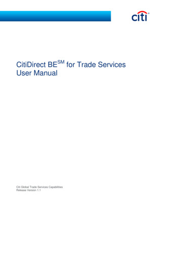
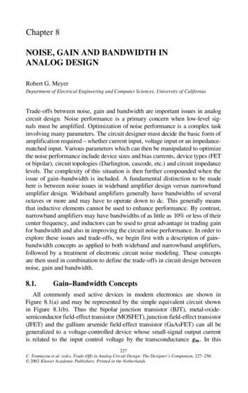
GPIOANTENNASWITCHPOWERMGMTEXT. ANTJTAGInductorGPIOExternal main SPIdevicesChipantenna64Mb FLASHAT45DB641ERADIOAT86RF2336x 16bit timers63 GPIO/IRQSensorsActuators4x USARTSPIUARTI2CGPIOIRQCRC AESAnalogIRQGPIOEXT. ANT2xIRQUSB Host/DevSensorsPRIMARY SPIMAIN SPIUSBdevice16ch 12bit ADCMCUATSAM4LC8C16ch DMA9 async IRQs32bit RTC4x I2CFLASH4xPWMRADIOPARALLEL IO SYNC CAPTURE6xADCVREF /-XTALPOWER CFGMCUUSART FLOW CTLUSBFigure 1: The Storm platform architecture4.1OverviewWe begin with a brief overview of the platform beforediving into the components that constitute it. Figure 1 showsthe architecture of the Storm module in the main block, withcomponents on the carrier indicated outside the block. Theindividual parts and peripheral signals of the module are illustrated in Figure 2. Note that most of these signals aremultiplexed, and only one of their possible functionalities isindicated.4.2MicrocontrollerAlthough Section 3 concludes that an ARM Cortex-M4 isthe current best-in-class embedded processor, this does notnarrow down the available choices much. There are, at thetime of writing, 196 licensees of the Cortex-M family of intellectual property [7]. Each of these licensees representsI2CWith the context of available technology established, inthis section we address the first question posed by Section1: Is it possible for a system based on a fully-featured 32bit microprocessor to perform within a tight energy budget? We answer in the affirmative by way of example withStorm, a reference platform based on a SAM4L 48 MhzCortex-M4 microcontroller, AT86RF233 802.15.4 radio andAT45DB081E 8 Mbit flash that serves as both a set of design guidelines for constructing 32 bit platforms with “moteclass” energy budgets and as a means for empirical evaluation of such a system in Section 5.3.I2CCan a 32-bit processor be low powerenough?USART FLOW CTL4USART FLOW CTLreached general availability but represents a trend in industry. We predict that there will soon be a proliferation of suchSoCs at competitive prices.The next step from integration of the radio into the SoCis the integration of an energy source into the package,a concept which although not currently prevalent in massproduced products, has been proven possible with stackeddice [13].Figure 2: The Storm moduleone vendor who in turn combines this processor with various peripherals, memory and flash. Even after the all thefunctionality is fixed, different vendors use different fabrication processes, leading to different costs and energy usage.Table 4 shows a few of the hundreds of Cortex-M4 processors from a handful of vendors. These selections are all themost capable of their respective families, but not necessarilythe flagship family from the vendor.After evaluating several offerings from nearly a dozenvendors, a few guidelines emerged to narrow it down to thefinally selected chip – the ATSAM4L. These discriminatorswere, in the order of efficacy: The available flash and RAM on the chip The available packaging and pin count The availability of the product – many very promisingchips are advertised as being available but are in factseveral months from production. The comprehensiveness of the documentation – if thenecessary figures of merit are not described in thedatasheet, they are evidently not important to the manufacturer. The current consumption of a useful low-power modeand its wake up time The granularity of its low power modesThe Atmel ATSAM4LC8CA, indicated in bold in Table 4,was chosen as it had best-in-class energy characteristics, sufficient flash, RAM and IO, as well as a comprehensive powermanagement system and significantly better documentation
VendorNXPSTMicroSilabsFreescaleAtmelTable 4: A small sample of available Cortex-M4 processorsDevicefmax (Mhz) SRAM(KB) Flash(KB) han other vendors.A noteworthy feature of the processor is that it has 16independent DMA channels. While the MSP430 familyhad DMA, the limited number of channels and the multiplexing of communication peripherals contained it’s implications. The SAM4L, however, has several more independentcommunication mechanisms, so the impact of the DMA isgreater.4.3RadioThe radio is an important component to select, as it isinescapably responsible for a significant share of the energybudget. Fortunately, as discussed in Section 3, there are onlya handful of choices available. These are laid out in Table 5.The Freescale offering is a (currently) unreleased SoC thatincludes a Cortex-M4 core on-die.As we are targeting compatibility with existing infrastructure, it made sense to use 2.4GHz IEEE 802.15.4, making thetwo obvious choices for the radio chip the second generationTI CC2520, and the Atmel AT86RF233. The CC2520 wouldbe the easier chip to develop support for, as it is the newerversion of the ubiquitous CC2420. The chip is, however,already more than five years old and lacks several featuresthat the newer Atmel chip offers. Both chips are the flagship 802.15.4 transceivers from their respective vendors atthe time of writing.One key difference between the Atmel and the TI chip isthat the AT86RF233 is capable of automatic retransmissionof packets that require acknowledgement but do not receiveit, enabling automatic CSMA/CA. The TI CC2520 does notautomatically perform CSMA/CA activities, although it doesexport the CCA line to the microcontroller directly, allowingfor faster manual response to an assessment than the in-bandCCA signal from the RF233.When combined with the peripheral event systems foundin modern microcontrollers, the automatic CSMA/CA withretransmission can offer significant advantages over the software CSMA/CA methods that are currently employed. TheSAM4L, for example, can be configured so that it sends awake up command to the radio, prepares the packet in memory and goes to sleep. When the radio IRQ line is assertedto indicate it is ready for transmission, the clock for the SPIclock domain is automatically started, the packet is copiedvia DMA from MCU memory to the radio and transmission is triggered. As soon as this process completes, theSPI clock is automatically stopped again all utilizing the peripheral event system. This means that the entire process ofsending a packet, from the radio wake up command to whenthe ACK is received, can be performed without waking upWake(µS)24042.721301.5the processor. With the CC2520, the MCU would need towake up, check for acknowledgement, wait some back-offtime if the acknowledgement did not arrive, and then triggerretransmission.For reception, both chips feature automatic acknowledgement. The CC2520 has the feature to specify which addresses should receive ACKs with the frame pending bit automatically set - this feature is not present on the RF233.This is quite useful if motes are utilizing the frame pending signal as, in the absence of this feature, the MCU wouldhave to wake up after frame reception, parse the address, determine if the bit should be set or not and configure the radioaccordingly before the ACK is sent. It was decided that thisdid not constitute a big enough problem to outweigh the automatic retransmission for two reasons, the first is that it islikely that the MCU will want to wake up and receive thepacket from the radio as soon as it is received anyway, so theburden of setting the frame pending bit may prove to be insignificant. The second is that, at least in our use cases, fullduplex communication tends to be short lived and the framep
model of a representative wireless embedded system into a physical instantiation by evaluation of available components and selective design trade-offs is discussed. A physical mod-ule design