Transcription
Post - Tensioned Concrete DesignFor ACI 318-08
ContentsPost-TensioningConcrete DesignCodesChapter 1Design for ACI 318-081.1Notations1-11.2Design Load Combinations1.2.1 Initial Service Load Combination1.2.2 Service Load Combination1.2.3 Long-Term Service Load Combination1.2.4 Strength Design Load Combination1-51-51-51-61-61.3Limit on Material Strength1-71.4Strength Reduction Factors1-71.5Design Assumptions for Prestressed Concrete1-81.6Serviceability Requirements of FlexuralMembers1.6.1 Serviceability Check at Initial ServiceLoad1.6.2 Serviceability Checks at Service Load1.6.3 Serviceability Checks at Long-TermService Load1.6.4 Serviceability Checks of PrestressingSteel1-101-101-101-111-111.7Beam Design1.7.1 Design Flexural Reinforcement1.7.2 Design Beam Shear Reinforcement1.7.3 Design Beam Torsion Reinforcement1-121-121-231-261.8Slab Design1.8.1 Design for Flexure1.8.2 Check for Punching Shear1.8.3 Design Punching Shear Reinforcement1-311-311-331-37
Post-TensionedConcreteDesignfor ACI 318-08Herein describes in detail the various aspects of the post-tensioned concretedesign procedure with the American code ACI 318-08 [ACI 2008]. Variousnotations used in this chapter are listed in Table 1-1. For referencing to thepertinent sections of the ACI code in this chapter, a prefix “ACI” followed bythe section number is used.1.1NotationsThe following table identifies the various notations used in this chapter.Notations1-1
Post-Tensioned Concrete DesignTable 1-1 List of Symbols Used in the ACI 318-08 Code1-2AcpArea enclosed by the outside perimeter of the section, inAgGross area of concrete, in 2AlTotal area of longitudinal reinforcement to resist torsion, inAoArea enclosed by the shear flow path, sq-inAohArea enclosed by the centerline of the outermost closedtransverse torsional reinforcement, sq-inApsArea of prestressing steel in flexural tension zone, in 2AsArea of tension reinforcement, in 2A'sArea of compression reinforcement, in 2As(required)Area of steel required for tension reinforcement, inAt /sArea of closed shear reinforcement per unit length of memberfor torsion, sq-in/inAvArea of shear reinforcement, inAv /sArea of shear reinforcement per unit length of member, in 2/inaDepth of compression block, inabDepth of compression block at balanced condition, inamaxMaximum allowed depth of compression block, inbWidth of member, inbfEffective width of flange (T-beam section), inbwWidth of web (T-beam section), inb0Perimeter of the punching critical section, inb1Width of the punching critical section in the direction ofbending, inb2Width of the punching critical section perpendicular to thedirection of bending, incDepth to neutral axis, incbDepth to neutral axis at balanced conditions, inNotations2222
Chapter1- Designfor ACI 318-08Table 1-1 List of Symbols Used in the ACI 318-08 CodedDistance from compression face to tension reinforcement, ind'Concrete cover to center of reinforcing, indeEffective depth from compression face to centroid of tensionreinforcement, indsThickness of slab (T-beam section), indpDistance from extreme compression fiber to centroid ofprestressing steel, inEcModulus of elasticity of concrete, psiEsModulus of elasticity of reinforcement, assumed as29,000,000 psi (ACI 8.5.2)f'cSpecified compressive strength of concrete, psif'ciSpecified compressive strength of concrete at time of initialprestress, psifpeCompressive stress in concrete due to effective prestressforces only (after allowance of all prestress losses), psifpsStress in prestressing steel at nominal flexural strength, psifpuSpecified tensile strength of prestressing steel, psifpySpecified yield strength of prestressing steel, psiftExtreme fiber stress in tension in the precompressed tensilezone using gross section properties, psifySpecified yield strength of flexural reinforcement, psifysSpecified yield strength of shear reinforcement, psihOverall depth of a section, inhfHeight of the flange, in Mn0Design moment resistance of a section with tendons only, NmmNotations 1 - 3
Post-Tensioned Concrete DesignTable 1-1 List of Symbols Used in the ACI 318-08 Code1-4 MnbalDesign moment resistance of a section with tendons and thenecessary mild reinforcement to reach the balanced condition,N-mmMuFactored moment at section, lb-inNcTension force in concrete due to unfactored dead load pluslive load, lbPuFactored axial load at section, lbsSpacing of the shear reinforcement along the length of thebeam, inTuFactored torsional moment at section, lb-inVcShear force resisted by concrete, lbVmaxMaximum permitted total factored shear force at a section, lbVuFactored shear force at a section, lbVsShear force resisted by steel, lb 1Factor for obtaining depth of compression block in concrete cRatio of the maximum to the minimum dimensions of thepunching critical section cStrain in concrete c, maxMaximum usable compression strain allowed in extremeconcrete fiber (0.003 in/in) ps sStrain in prestressing steel s,minStrain in reinforcing steel Minimum tensile strain allowed in steel reinforcement atnominal strength for tension controlled behavior (0.005 in/in) Strength reduction factor fFraction of unbalanced moment transferred by flexure vFraction of unbalanced moment transferred by eccentricity ofshearNotations
Chapter1- Designfor ACI 318-08Table 1-1 List of Symbols Used in the ACI 318-08 Code1.2 Shear strength reduction factor for light-weight concrete Angle of compression diagonals, degreesDesignLoadCombinationsThe design load combinations are the various combinations of the load casesfor which the structure needs to be designed. For ACI 318-08, if a structure issubjected to dead (D), live (L), pattern live (PL), snow (S), wind (W), andearthquake (E) loads, and considering that wind and earthquake forces arereversible, the load combinations in the following sections may need to be considered (ACI 9.2.1).For post-tensioned concrete design, the user can specify the prestressing load(PT) by providing the tendon profile. The default load combinations for posttensioning are defined in the following sections.1.2.1Initial Service LoadCombinationThe following load combination is used for checking the requirements at transfer of prestress forces, in accordance with ACI 318-08 clause 18.4.1. Theprestressing forces are considered without any long-term loses for the initialservice load combination check.1.0D 1.0PT1.2.2(ACI 18.4.1)Service LoadCombinationThe following load combinations are used for checking the requirements ofprestress for serviceability in accordance with ACI 318-08 clauses 18.3.3,18.4.2(b), and 18.9.3.2. It is assumed that all long-term losses have already occurred at the service stage.1.0D 1.0PT1.0D 1.0L 1.0PT(ACI 18.4.2(b))Design Load Combinations 1 - 5
Post-Tensioned Concrete Design1.2.3Long-TermService LoadCombinationThe following load combinations are used for checking the requirements ofprestress in accordance with ACI 318-08 clause 18.4.2(a). The permanent loadfor this load combination is taken as 50 percent of the live load. It is assumedthat all long-term losses have already occurred at the service stage.1.0D 1.0PT1.0D 0.5L 1.0PT1.2.4(ACI 18.4.2(b))StrengthDesignLoadCombinationThe following load combinations are used for checking the requirements ofprestress for strength in accordance with ACI 318-08, Chapters 9 and 18.The strength design combinations required for shear design of beams andpunching shear require the full PT forces (primary and secondary). Flexural design requires only the hyperstatic (secondary) forces. The hyperstatic (secondary) forces are automatically determined by subtracting out the primary PTmoments when the flexural design is carried out.1.4D 1.0PT*(ACI 9.2.1)1.2D 1.6L 1.0PT*1.2D 1.6(0.75 PL) 1.0PT(ACI 9.2.1)*(ACI 9.2.1, 13.7.6.3)0.9D 1.6W 1.0PT1.2D 1.0L 1.6W 1.0PT*(ACI 9.2.1)0.9D 1.0E 1.0PT1.2D 1.0L 1.0E 1.0PT*(ACI 9.2.1)1.2D 1.6L 0.5S 1.0PT*1.2D 1.0L 1.6S 1.0PT*(ACI 9.2.1)1.2D 1.6S 0.8W 1.0PT*1.2D 1.0L 0.5S 1.6W 1.0PT*(ACI 9.2.1)1.2D 1.0L 0.2S 1.0E 1.0PT(ACI 9.2.1)***1-6— Replace PT by H for flexural design onlyDesign Load Combinations*
Chapter1- Designfor ACI 318-08The IBC 2006 basic load combinations (Section 1605.2.1) are the same. Thesealso are the default design load combinations whenever the ACI 31808 code is used. The user should use other appropriate load combinations ifroof live load is treated separately, or if other types of loads are present.1.3Limits onMaterial StrengthThe concrete compressive strength, f' c, should not be less than 2500 psi (ACI5.1.1). The upper limit of the reinforcement yield strength, f y, is taken as 80 ksi(ACI 9.4) and the upper limit of the reinforcement shear strength, f yt, is taken as60 ksi (ACI 11.5.2).This procedure enforces the upper material strength limits for flexure andshear design of beams and slabs or for torsion design of beams. The inputmaterial strengths are taken as the upper limits if they are defined in thematerial properties as being greater than the limits. The user is responsible forensuring that the minimum strength is satisfied.1.4StrengthReductionFactorsThe strength reduction factors, , are applied on the specified strength to obtainthe design strength provided by a member. The factors for flexure, shear, andtorsion are as follows: t 0.90 for flexure (tension controlled)(ACI 9.3.2.1) c 0.65 for flexure (compression controlled) 0.75 for shear and torsion.(ACI 9.3.2.2(b))(ACI 9.3.2.3)The value of varies from compression-controlled to tension-controlled basedon the maximum tensile strain in the reinforcement at the extreme edge, t(ACI 9.3.2.2).Sections are considered compression-controlled when the tensile strain in theextreme tension reinforcement is equal to or less than the compressioncontrolled strain limit at the time the concrete in compression reaches its assumed strain limit of c.max, which is 0.003. The compression-controlled strainLimits on Material Strength 1 - 7
Post-Tensioned Concrete Designlimit is the tensile strain in the reinforcement at the balanced strain condition,which is taken as the yield strain of the reinforcement, (f y/E) (ACI 10.3.3).Sections are tension-controlled when the tensile strain in the extreme tensionreinforcement is equal to or greater than 0.005, just as the concrete in compression reaches its assumed strain limit of 0.003 (ACI 10.3.4).Sections with t between the two limits are considered to be in a transition region between compression-controlled and tension-controlled sections (ACI10.3.4).When the section is tension-controlled, t is used. When the section is compression-controlled, c is used. When the section is in the transition region, islinearly interpolated between the two values (ACI 9.3.2).1.5DesignAssumptions for PrestressedConcreteStrength design of prestressed members for flexure and axial loads shall bebased on assumptions given in ACI 10.2. The strain in the reinforcement and concrete shall be assumed directly proportional to the distance from the neutral axis (ACI 10.2.2). The maximum usable strain at the extreme concrete compression fiber shallbe assumed equal to 0.003 (ACI 10.2.3). The tensile strength of the concrete shall be neglected in axial and flexuralcalculations (ACI 10.2.5). The relationship between the concrete compressive stress distribution and theconcrete strain shall be assumed to be rectangular by an equivalent rectangular concrete stress distribution (ACI 10.2.7). The concrete stress of 0.85f' c shall be assumed uniformly distributed over anequivalent-compression zone bounded by edges of the cross-section and astraight line located parallel to the neutral axis at a distance a 1c from thefiber of maximum compressive strain (ACI 10.2.7.1).1-8DesignAssumptions fo r Prestressed Concrete
Chapter1- Designfor ACI 318-08 The distance from the fiber of maximum strain to the neutral axis, c shall bemeasured in a direction perpendicular to the neutral axis (ACI 10.2.7.2).Elastic theory shall be used with the following two assumptions: The strains shall vary linearly with depth through the entire load range (ACI18.3.2.1). At cracked sections, the concrete resists no tension (ACI 18.3.2.1). Prestressedconcrete members are investigated at the following three stages(ACI 18.3.2): At transfer of prestress force At service loading At nominal strengthThe prestressed flexural members are classified as Class U (uncracked), ClassT (transition), and Class C (cracked) based on ft , the computed extreme fiberstress in tension in the precompressed tensile zone at service loads (ACI18.3.3).The precompressed tensile zone is that portion of a prestressed member whereflexural tension, calculated using gross section properties, would occur underunfactored dead and live loads if the prestress force was not present.Prestressed concrete is usually designed so that the prestress force introducescompression into this zone, thus effectively reducing the magnitude of thetensile stress.For Class U and Class T flexural members, stresses at service load aredetermined using uncracked section properties, while for Class C flexuralmembers, stresses at service load are calculated based on the crackedsection (ACI18.3.4).A prestressed two-way slab system is designed as Class U only withf t 6 f 'c (ACI R18.3.3); otherwise, an over-stressed (O/S) condition is reported.DesignAssumptions for PrestressedConcrete 1 - 9
Post-Tensioned Concrete DesignThe following table provides a summary of the conditions considered for thevarious section classes.PrestressedClass UClass TClass CNonprestressedAssumed behaviorUncrackedTransition betweenuncracked and crackedCrackedCrackedSection properties for stresscalculation at service loadsGross section18.3.4Gross section18.3.4Cracked section18.3.4No requirementAllowable stress at transfer18.4.118.4.118.4.1No requirementAllowable compressive stress basedon uncracked section properties18.4.218.4.2No requirementNo requirementTensile stress at service loads18.3.3 7.5 f c No requirementNo requirement7.5 f c ft 12 f c 1.6Serviceability Requirements of Flexural Members1.6.1Serviceability Check at Initial Service LoadThe stresses in the concrete immediately after prestress force transfer (beforetime dependent prestress losses) are checked against the following limits: Extreme fiber stress in compression:0.60 f ci'(ACI 18.4.1(a)) Extreme fiber stress in tension:3 f ci'(ACI 18.4.1(b))6 f ci'(ACI 18.4.1(c)) Extreme fiber stress in tension at ends ofsimply supported members:1.6.2Serviceability Checks at Service LoadThe stresses in the concrete for Class U and Class T prestressed flexural members at service loads, and after all prestress losses occur, are checked againstthe following limits:1 - 10Serviceability Requirements of Flexural Members
Chapter1- Designfor ACI 318-08 Extreme fiber stress in compression dueto prestress plus total load:0.60 f c'(ACI 18.4.2(b)) Extreme fiber stress in tension in the precompressed tensile zone at serviceloads:– Class U beams and one-way slabs:f t 7.5 f 'c(ACI 18.3.3)– Class U two-way slabs:f t 6 f 'c(ACI 18.3.3)– Class T beams:– Class C beams:7.5 f 'c f t 12 f 'cf t 12 f 'c(ACI 18.3.3)(ACI 18.3.3)For Class C prestressed flexural members, checks at service loads are not required by the code. However, for Class C prestressed flexural members notsubject to fatigue or to aggressive exposure, the spacing of bonded reinforcement nearest the extreme tension face shall not exceed that given by ACI10.6.4 (ACI 18.4.4). It is assumed that the user has checked the requirements ofACI 10.6.4 and ACI 18.4.4.1 to 18.4.4 independently.1.6.3Serviceability Checks at Long-TermService LoadThe stresses in the concrete for Class U and Class T prestressed flexural members at long-term service loads, and after all prestress losses occur, are checkedagainst the same limits as for the normal service load, except for the following: Extreme fiber stress in compression due to prestress plus total load:0.45 fc'1.6.4(ACI 18.4.2(a))Serviceability Checks of PrestressingSteelPerform checks on the tensile stresses in the prestressing steel (ACI 18.5.1).The permissible tensile stress checks, in all types ofServiceability Requirements of Flexural Members 1 - 11
Post-Tensioned Concrete Designprestressing steel, in terms of the specified minimum tensile stress fpu, and theminimum yield stress, fy, are summarized as follows: Due to tendon jacking force:min(0.94fpy, 0.80fpu)(ACI 18.5.1(a)) Immediately after force transfer:min(0.82fpy, 0.74fpu)(ACI 18.5.1(b))0.70fpu(ACI 18.5.1(c)) At anchors and couplers after forcetransfer:1.7BeamDesignIn the design of prestressed concrete beams, calculates and reports the requiredareas of reinforcement for flexure, shear, and torsion based on the beammoments, shear forces, torsion, load combination factors, and other criteriadescribed in the subsections that follow. The reinforcement requirements arecalculated at each station along the length of the beam.Beams are designed for major direction flexure, shear, and torsion only. Effectsresulting from any axial forces and minor direction bending that may exist inthe beams must be investigated independently by the user.The beam design procedure involves the following steps: Design flexural reinforcement Design shear reinforcement Design torsion reinforcement1.7.1Design Flexural ReinforcementThe beam top and bottom flexural reinforcement is designed at each stationalong the beam. In designing the flexural reinforcement for the major momentof a particular beam for a particular station, the following steps are involved: Determine factored moments Determine required flexural reinforcement1 - 12BeamDesign
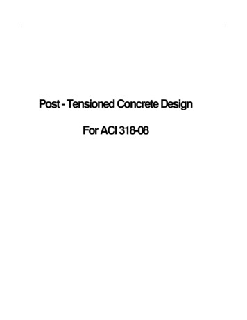
Chapter1- Designfor ACI 318-081.7.1.1Determine Factored MomentsIn the design of flexural reinforcement of prestressed concrete beams, thefactored moments for each load combination at a particular beam station areobtained by factoring the corresponding moments for different load cases,with the corresponding load factors.The beam is then designed for the maximum positive and maximum negativefactored moments obtained from all of the load combinations. Positive beammoments can be used to calculate bottom reinforcement. In such cases thebeam may be designed as a rectangular or a flanged beam. Negative beammoments can be used to calculate top reinforcement. In such cases the beammay be designed as a rectangular or inverted flanged beam.1.7.1.2Determine Required Flexural ReinforcementIn the flexural reinforcement design process, both the tension and compressionreinforcement shall be calculated. Compression reinforcement is added whenthe applied design moment exceeds the maximum moment capacity of a singlyreinforced section. The user has the option of avoiding the compressionreinforcement by increasing the effective depth, the width, or the strength ofthe concrete.The design procedure is based on the simplified rectangular stress block, asshown in Figure 1-1 (ACI 10.2). Furthermore, it is assumed that the net tensilestrain in the reinforcement shall not be less than 0.005 (tension controlled)(ACI 10.3.4). When the applied moment exceeds the moment capacity at thisdesign condition, the area of compression reinforcement is calculated on theassumption that the additional moment will be carried by compressionreinforcement and additional tension reinforcement.The design procedure used , for both rectangular and flanged sections(L- and T-beams), is summarized in the subsections that follow. It is assumedthat the design ultimate axial force does not exceed (0.1f' A) (ACI 10.3.5);c ghence all beams are designed for major direction flexure, shear, and torsiononly.BeamDesign 1 - 13
Post-Tensioned Concrete Design1.7.1.2.1Design of Rectangular BeamsThe process first determines if the moment capacity provided by the post-tensioningtendons alone is enough. In calculating the capacity, it is assumed that A s 0.In that case, the moment capacity M 0n is determined as follows:0.85 f c 0.003bA sAd Csca 1cdpdsAps ps igure 1-1 Rectangular Beam DesignThe maximum depth of the compression zone, c max, is calculated based on thelimitation that the tension reinforcement strain shall not be less than smin, whichis equal to 0.005 for tension-controlled behavior (ACI 10.3.4): c max d c max smin c max (ACI 10.2.2)where, cmax 0.003(ACI 10.2.3) smin 0.005(ACI 10.3.4)Therefore, the limit c c max is set for tension-controlled sections.1 - 14BeamDesign
Chapter1- Designfor ACI 318-08The maximum allowable depth of the rectangular compression block, a max, isgiven by:a max 1cmax(ACI 10.2.7.1)where 1 is calculated as: f ' 4000 1 0.85 0.05 c , 1000 0.65 1 0.85(ACI 10.2.7.3)The process determines the depth of the neutral axis, c, by imposing forceequilibrium, i.e., C T. After the depth of the neutral axis has beendetermined, the stress in the post-tensioningsteel, f , is computed based onpsstrain compatibilityfor bonded tendons. For unbonded tendons, the code equations are used tocompute the stress, f ps in the post-tensioning steel.Based on the calculated f ps, the depth of the neutral axis is recalculated, and f psis further updated. After this iteration process has converged, the depth of therectangular compression block is determined as follows:a 1c If c cmax (ACI 10.3.4), the moment capacity of the section, provided bypost-tensioning steel only, is computed as:a M n0 Aps f ps d p 2 If c cmax (ACI 10.3.4), a failure condition is declared.If Mu M n0 , calculates the moment capacity and the Asrequired atthe balanced condition. The balanced condition is taken as the marginal tensioncontrolled case. In that case, it is assumed that the depth of the neutral axis, c isequal to cmax. The stress in the post-tensioning steel, f ps is then calculated and thearea of required tension reinforcement, A s, is determined by imposing forceequilibrium, i.e., C T.C 0.85 f c'amaxbBeamDesign 1 - 15
Post-Tensioned Concrete DesignT Aps f psbal Asbal f sbalbalsA 0.85 fc amaxb Aps f psbalf sbalAfter the area of tension reinforcement has been determined, the capacity of thesection with post-tensioning steel and tension reinforcement is computed as:a a M nbal Aps f psbal d p max Asbal fs bal d s max 2 2 In that case, it is assumed that the bonded tension reinforcement will yield,which is true for most cases. In the case that it does not yield, the stress in thereinforcement, f s, is determined from the elastic-perfectly plastic stress-strainrelationship. The f y value of the reinforcement is then replaced with f s in thepreceding four equations. This case does not involve any iteration indetermining the depth of the neutral axis, c.1.7.1.2.1.1 Case 1: Post-tensioningsteel is adequateWhen Mu M n0 , the amount of post-tensioning steel is adequate to resist thedesign moment M u. Minimum reinforcement is provided to satisfy ductility requirements (ACI 18.9.3.2 and 18.9.3.3), i.e., M u M n0 .1.7.1.2.1.2 Case 2: Post-tensioningsteel plus tension reinforcementIn this case, the amount of post-tensioning steel, A ps, alone is not sufficient toresist Mu, and therefore the required area of tension reinforcement is computedto supplement the post-tensioning steel. The combination of post-tensioningsteel and tension reinforcement should result in a a max.When M 0n M u M nbal ,determines the required area of tension re-inforcement, A s, iteratively to satisfy the design moment M u and reports this required area of tension reinforcement. Since M u is bounded by M n0 at thebal0lower end and M n at the upper end, and M n is associated with As 0baland Mbaln is associated with As As , the required area will fall within therange of 0 to A sbal.1 - 16BeamDesign
Chapter1- Designfor ACI 318-08The tension reinforcement is to be placed at the bottom if M u is positive, or atthe top if Mu is negative.1.7.1.2.1.3 Case 3: Post-tensioningsteel andtension reinforcement are notadequateWhen M u M nbal , compression reinforcement is required (ACI 10.3.5). Inthis case assumes that the depth of the neutral axis, c, is equal to c .maxThe values of fps and fs reach their respective balanced condition values, f psbaland f sbal . The area of compression reinforcement, As' , is then determined asfollows:The moment required to be resisted by compression reinforcement and tensionreinforcement is:M us M u M nbalThe required compression reinforcement is given by:A 's M us, where f 's 0.85 f 'c d e d ' c d ' f ' s Es c max max fy c max (ACI 10.2.2, 10.2.3, 10.2.4)The tension reinforcement for balancing the compression reinforcement isgiven by:Ascom M usf y d s d ' Therefore, the total tension reinforcement, A s Asbal Ascom , and the totalcompression reinforcement is A' s. A s is to be placed at the bottom and A' s is tobe placed at the top if M u is positive, and vice versa if M u is negative.BeamDesign 1 - 17
Post-Tensioned Concrete Design1.7.1.2.2Designof FlangedBeams1.7.1.2.2.1 Flanged BeamUnder Negative MomentIn designing for a factored negative moment, M u (i.e., designing top reinforcement), the calculation of the reinforcement area is exactly the same as above,i.e., no flanged beam data is used.1.7.1.2.2.2 Flanged BeamUnder Positive MomentThe process first determines if the moment capacity provided by the post-tensioningtendons alone is enough. In calculating the capacity, it is assumed that A s 0.In that case, the moment capacity M 0n is determined as follows:The maximum depth of the compression zone, c max, is calculated based on thelimitation that the tension reinforcement strain shall not be less than smin, whichis equal to 0.005 for tension-controlled behavior (ACI 10.3.4): c max d c max s min c max (ACI 10.2.2)where, cmax 0.003(ACI 10.2.3) smin 0.005(ACI 10.3.4)Therefore, the limit c c max is set for tension-controlled section:The maximum allowable depth of the rectangular compression block, a max, isgiven by:a max 1cmax(ACI 10.2.7.1)where 1 is calculated as: f 'c 4000 , 1000 1 0.85 0.05 1 - 18BeamDesign0.65 1 0.85(ACI 10.2.7.3)
Chapter1- Designfor ACI 318-08d A s0.85 f c 0.003hfbff sCsCfcdpdsCwApsAs0.85 f c ps re 1-2 T-Beam DesignThe pr ocess determines the depth of the neutral axis, c, by imposing forceequilibrium, i.e., C T. After the depth of the neutral axis has beendetermined, thestress in the post-tensioning steel, f ps is computed based on strain compatibilityfor bonded tendons. For unbonded tendons, the code equations are used tocompute the stress, f ps in the post-tensioning steel. Based on the calculated f ps,the depth of the neutral axis is recalculated, and f ps is further updated. After thisiteration process has converged, the depth of the rectangular compression blockis determined as follows:a 1c If c cmax (ACI 10.3.4), the moment capacity of the section, provided bypost-tensioning steel only, is computed as:a M n0 Aps f ps d p 2 If c cmax (ACI 10.3.4), a failure condition is declared.If Mu M n0 , calculates the moment capacity and the Asrequired atthe balanced condition. The balanced condition is taken as the marginal tension-controlled case. In that case, it is assumed that the depth of the neutralBeamDesign 1 - 19
Post-Tensioned Concrete Designaxis c is equal to c max. The stress in the post-tensioning steel, f ps, is then calculated and the area of required tension reinforcement, A s, is determined by imposing force equilibrium, i.e., C T. If a hf, the subsequent calculations for A s are exactly the same as previouslydefined for the rectangular beam design. However, in that case the width ofthe beam is taken as b f. Compression reinforcement is required if a a max. If a hf, the calculation for A s is given by:C 0.85 f 'c Accompwhere Accom is the area of concrete in compression, i.e.,Accom b f h f bw amax h f T Aps f psbal Asbal f sbalAsbal 0.85 f 'c Accom Aps f psbalf sbalIn that case, it is assumed that the bonded tension reinforcement will yield,which is true for most cases. In the case that it does not yield, the stress in thereinforcement, f s, is determined from the elastic-perfectly plastic stress-strainrelationship. The f y value of the reinforcement is then replaced with f s in thepreceding four equations. This case does not involve any iteration indetermining the depth of the neutral axis, c.Case 1: Post-tensioningsteel is adequateWhen M u M n0 the amount of post-tensioning steel is adequate to resist thedesign moment M u. Minimum reinforcement is provided to satisfy ductility requirements (ACI 18.9.3.2 and 18.9.3.3), i.e., M u M n0 .Case 2: Post-tensioningsteel plus tensionreinforcementIn this case, the amount of post-tensioning steel, A ps, alone is not sufficient toresist Mu, and therefore the required area of tension reinforcement is computed1 - 20BeamDesign
Chapter1- Designfor ACI 318-08to supplement the post-tensioning steel. The combination of post-tensioningsteel and tension reinforcement should result in a a max.When M 0n M u M nbal ,determines the required area of tension re-inforcement, A s, iteratively to satisfy the design moment M u and reports this required area of tension reinforcement. Since M u is bounded by M n0 at thelower end and M balat the upper end, and M n0 is associated with As 0nis associated with As Asbal , the required area will fall within theand M balnrange of 0 to A s.The tension reinforcement is to be placed at the bottom if M u is positive, or atthe top if Mu is negative.Case 3: Post-tensioningsteel andtens ionreinforc
A 2 2Area 2 A' c 2 2 Post-Tensioned Concrete Design Table 1-1 List of Symbols Used in the ACI 318-08 Code cp Area enclosed by the outside perimeter of the section, in A g Gross area of concrete, in A 2 l Total area of longitudinal reinforcement to resist torsion, in A o Area enclosed by the shear flow path, sq-in A o