Transcription
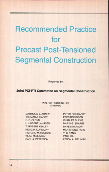
Recommended PracticeforPrecast Post-TensionedSegmental ConstructionReported byJoint PCI-PTI Committee on Segmental ConstructionWALTER PODOLNY, JR.(Chairman)MAHMOUD Z. ARAFATTHOMAS J. D'ARCYC. S. GLOYDH. HUBERT JANSSENT. ROBERT KEALEYHEINZ P. KORETZKYRICHARD M. McCLUREVILAS MUJUMDARCARL A. PETERSON14PETER REINHARDTFRED ROBINSONCHARLES SLAVISMARIO G. SUAREZDAVE SWANSONMAN-CHUNG TANGY. C. YANGPAUL ZIAZENON A. ZIELINSKI
SynopsisThis Joint PCI-PTI committee report presentsbasic recommendations for the design andconstruction of precast post-tensioned concretestructures which are composed of individualsegments that are connected by the use ofpost-tensioning. The recommendations cover thefabrication, transportation, and erection of theprecast component segments, details of theconstruction of joints, tendons and anchors, anddesign considerations applicable to segmentalconstruction.It should be emphasized that this report ispublished as a guide on segmental construction andshould not be considered a specification. The reportcontained herein is an update of the report entitled"Recommended Practice for SegmentalConstruction in Prestressed Concrete," published inthe March-April 1975 PCI JOURNAL.PCI JOURNALlJanuary- February 198215
CONTENTSChapter 1Introduction . 181.1 General1.2 Historical Background1.3 Limitations of this Recommended Practice1.4 Scope1.5 DefinitionsChapter 2 — Examples of Segmental Construction . 192.1 General2.2 Airport Control Tower2.3 Liquid Natural Gas Storage Tanks2.4 28-Story Office Building2.5 Cement Clinker Silo2.6 Floating Vessel for Storage of Liquified Petroleum Gas2.7 Five Points Station, MARTA Rapid Transit, Atlanta, Georgia2.8 Precast Segmental Bridge Construction2.8.1 Balanced Cantilever2.8.2 Span-by -Span2.8.3 Progressive Placing2.8.4 Incremental LaunchingChapter 3 — Fabrication of Precast Segments . 363.1 General Considerations3.2 Methods of Casting3.2.1 The Long-Line Method3.2.2 The Short-Line Method3.3 Formwork3.3.1 General3.3.2 Provisions for Tendons3.3.3 Provisions for Supplemental Reinforcement3.3.4 Tolerances3.4 Concrete3.5 Joint Surfaces3.5.1 Quality3.5.2 Holes for Tendons and Couplers3.6 Bearing AreasChapter 4 — Transportation, Storage and ErectionofPrecast Segments . 444.1 General4.2 Plant Handling and Transportation4.3 Erection Methods16
4.3.1 Cranes4.3.2 Winch and Beam4.3.3 Launching Girder4.4 Erection Considerations4.5 Erection Tolerances48Chapter5 -- Joints .5.1 General5.2 Cast-in-Place Joints5.3 Dry-Packed Joints5.4 Grouted Joints5.5 Match Cast Joints5.5.1 Epoxy Bonded Joints5.5.1.1 Selection of Epoxy5.5.1.2 Application of Epoxy5.5.2 Dry Joints5.6 Metal JointsChapter 6— Post -Tensioning Tendons . 536.1 Sheathing6.2 Tendon Couplers6.3 Anchor Plates6.3.1 Anchor Plates Cast into Precast Segments6.3.2 Anchor Plates Placed against Precast Surface6.4 Tendon Layout6.5 Placement and Stressing of Tendons6.6 Grouting6.7 External TendonsChapter 7 — Design Considerations . 577.1 General7.2 Force Redistribution7.3 Handling and Storage of Segments7.4 Joint Design7,4.1 Shear7.4.2 Keys7.4.3 Compression7.5 Auxiliary Reinforcement7.6 Design of Segments for Box Girder Bridges7.7 Design of Segments for Decked I-BeamsReferencesPCI. 60JOURNAUJanuary- February198217
CHAPTER 1 -- INTRODUCTION1.1 GeneralPrecast post-tensioned segmentalconstruction is defined as a methodof construction for bridges, buildings, tanks, silos, cooling towers,tunnels and other structures inwhich primary load carrying members are composed of precast concrete segments post-tensioned together.1.2 Historical BackgroundThe concept of dividing precastconcrete structural members intosmaller segments and connectingthem with stressed rods or barsdates back as far as 1888 to 1907and early ideas about prestressedconcrete by Dohring, Mandl, Lundand others.'Five bridges designed in Europeof a segmental precast girder typewere constructed between 1946and 1950. These girders were prestressed longitudinally, verticallyand transversely. The 240-ft (73 m)spans were flat two-hinged portalframe structures with adjustablehinged bearings to compensate forshortening due to shrinkage andcreep of concrete. 42 In 1951, asmall number of bridge girders inthe United States were built of precast concrete blocks. These blockswere strung onto prestressing cables, joints of the net section weremortared, harped tendons werepost-tensioned, and tendons weregrouted.s In the United States in1952 a single span girder bridgewas constructed by dividing eachgirder into three precast segments.After curing, the segments were reassembled at the site with coldjoints and post-tensioned.418Thirty-two major bridges outsideof North America were reviewed(in 1971) in a state-of the-art paperabout segmental bridges." Thesebridges were built between theyears 1960 and 1969. Many designparameters resulted in variations inspan, number of segment cells,span-depth ratios, segment lengths,joints, types, and erection methods.Six more bridges in various countries were reviewed in anotherstate-of-the-art paper published in1975. In North America well over 50box girder bridges of segmentalconstruction have either been builtor are under construction. In 1977 acable-stayed precast post-tensionedsegmental bridge was completed."The Portland Cement AssociationIibrary has two annotated bibliographies,9' 10 available for review,which list 195 articles on segmentaland cantilever cast-in-place bridgeconstruction between 1962 and1975.Although the term segmental hasmost often been applied to bridgeconstruction the concept of usingsegmental construction has beensuccessfully utilized in many projects other than bridges. For example: the Mutual Life Building inNorth Carolina; Gulf Life Tower inJacksonville, Florida; the FivePoints Station — MARTA RapidTransit, Atlanta, Georgia; the Velodrome and Olympic Stadiumstructures in Montreal, Canada; andnumerous buildings using shellsand roof girders.","Chapter 2 presents examples ofthe varied use of precast posttensioned segmental construction.
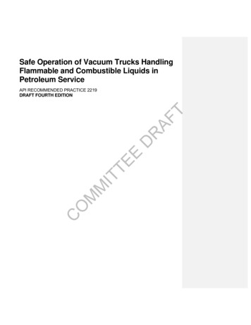
1.3 Limitations of thisRecommended PracticeThis report is a recommendedpractice on segmental construction,not a building code or specification.It is presented as a guide to the design and construction of structuresusing segmental elements to insuresafety and serviceability. Engineering judgment must beapplied to these recommendations.1.4 ScopeThese recommendations are intended to cover those conditionswhich affect segmentally constructed members differently fromnon-segmentally constructed members. They consider the fabrication,transportation, and erection of theprecast component segments, theconstruction of joints, tendons andanchors, and design considerationsapplicable to segmental construction.1.5 DefinitionsAdhesive —A bonding materialused in joints.Anchorage — The means bywhich the prestressing force istransmitted from the prestressingsteel to the concrete.Coating —Material used to protect the prestressing steel againstcorrosion and/or provide lubrication.Couplers — Hardware to transmitthe prestressing force from onepartial length prestressing tendonto another.Grout —A mixture of cement,and water with or without admixtures. (In some instances sand isused as a filler).Joint — The region of the structure between interfaces of precastsegments with or without adhesiveor grouting materials and with orwithout reinforcement.Prestressing Steel —The part of apost-tensioning tendon which iselongated and anchored to providethe necessary permanent prestressing force.Segment — A precast elementmade out of concrete, with or without reinforcement, prestressed ornon-prestressed.Sheathing or Duct — Enclosurearound the prestressing steel.Tendon — The complete assembly for post-tensioning, consistingof anchorages, couplers, and prestressing steel with sheathing.CHAPTER 2- EXAMPLES OF SEGMENTALCONSTRUCTION2.1 General2.2 Airport Control TowerMany structures have been designed and built using some variation of the concept of segmentalconstruction. The following examples are only a small portion ofthose built. These were recentlyreported in technical journals.In 1973 a 180-ft (54.86 m) highairport control tower' 3 consisting offour service cores was segmentallyconstructed using box segmentsapproximately 10 ft (3 m) square inplan and 7' ft (2.3 m) high. Thefour cores are topped by a 16-ftPCI JOURNAIJJanuary-February 198219
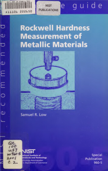
!1I ilFig. 1(a). Airport control tower. Structuralsteel platforms were set at 15-ft (4.57 m)intervals to connect the four service cores.Fig. 1(b). Erection of precast boxsegments. Note that the modules werestacked to 180-ft (54.9 m) height.VERTICALPOST TEN SIONINPRECASTCOREELEMENTDRY PACKEDJOINTSHIM SFig. 1(c). Setting of box segments.ceFig. 2. Isometric view of stacked boxsegments. Sketch shows the majorcomponents of segment.
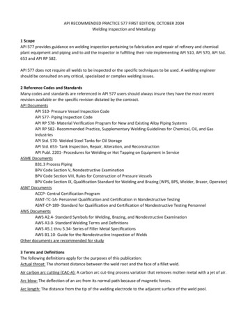
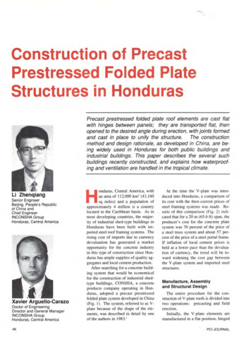
Fig. 3. Erection of precast panel for liquid natural gas storage tank.(4.88 m) high steel cab housing thecontrol tower observation deck andfacilities. Vertical post-tensioningwas used to stabilize the core segments during construction and provide moment and shear capacity toresist service loads. Fig. 1 showsthe tower during construction. Fig.2 is an isometric view of thestacked and post-tensioned boxsegments.PCI JOURNAL/January-February 19822.3 Liquid Natural GasStorage TanksIn 1974 in the United States, two900,000 bb] liquid natural gas storage tanks14 were completed using 8x 60 ft (2.44 x 18.3 m) high precastwall panels. After completion oferection of the panels the structurewas post-tensioned circumferentially. The tanks are composed oftwo concentric walls, the outer wall21
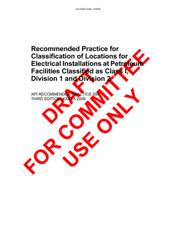
Fig. 4a. Plan of liquid natural gas tank.having a radius of 134 ft (40.8 m)and being 13 ft (4 m) beyond theinner wall. Three feet (0.9 m) of insulating material is placed in theannular space beside the innerwall. Mass concrete fills the other10 ft (3 m) providing resistance toexternal impact forces. Fig. 4a is aplan view showing the segmentsplaced side by side. Fig. 4b shows asection of the double wall and thecircumferential post-tensioning.Figs. 4c and 4d show the tanks invarious stages of construction.Fig. 4c. Precast panel being readied intoposition on tank wall. Note connectingdowels on side of panel.22
20'- 10 12" TOSUPPORTS3/B"PL ROOFINGTRUSS POCKETI8"INSULATIONCu M FE RENT A LoJClRPOST-TENSIONING WzLOWU)w -I.PRECAST WALL.,SEGMENTSwt- SHOTCRETETiWxMI Ujz\LIQUID EL.I2-9.LNGPRECASTWALLSEGMENTS00 m m'-10'-O" BERM3.-0"aSHOTCRETEFig. 4b. Section of double wall with post-tensioned precast wall segments.Fig. 4d. Overall view of LNG tanks during construction.PCI JOURNAUJanuary-February 198223
45'O" VIERENDEEL TRUSS— .,lI IIII IIii--- 1f «------- -------1 IIII MIIIIIIIII '.'wo jq W11IIIIl IIIIIII jl IIj 1II II I IIIIIIII II-'-iiIIIItlIIIIIIpijlIIIIIII! f .II I IIII IliIII II1---yt------ -- -Q IIN7IIIIWIIIQzIIII.I.oIi III -rIIiiIII!13IIIIIIiI fIIIjI,itJjIIEIIIF—yIII lilIIIIIili11I III IIIIIIIIIIIII I I I 1IIII11IIIIIIIII11IIIIIIIIIIII I-I IjlVIERENDEEL TRUSS-IIliIIIIit I IIII IIIfijLitIII Fig. 5. Plan view of 28-story office building.2.4 28-Story Office BuildingIn 1974, a 28-story office building15 used a segmentally constructed Vierendeel truss as theexterior support for the edges offloors. Truss segments were block-Ishaped, 17 ft (5.2 m) high, 10 ft (3m) wide at top and bottom andweighed a maximum of 9 tons (8.2t) each. The block-I's were erectedside by side at the site and the top24and bottom chords of the truss werepost-tensioned horizontally. Theends of the truss were then anchored into large cast-in-place columns. Fig, 5 is a plan view showingthe location of the trusses and columns. Fig. 6 is an elevation of asegmental Vierendeel truss. Further design and erection details ofthis building can be found in theNov.-Dec. 1975 PCI JOURNAL."
f COLUMNECOLUMN75 7"is 'hdo1 odoZII29'fz-ru4 ravr —ITB1IO'4TOP CHORDL c–Acv P RESTRESSINGATENDONCBOTTOM CHORDNEVIERENDEEL TRUSS — TYPICAL ELEVATION}0'2"BOTTOM GHDRDVIERENDEELSSTRUFLOOR LINEIj 8" 8 "18"10-7 BAR 10 BARS 15'-9";p r,q.p9o3 " 3t PRtSTRESSING TENDONC.I.P. COLUMNEND BLOCK ELEVATIONV7Fig. 6. Elevation of Vierendeel truss.SECT. A-ASECT. BBBSECT. CC
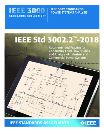
'T —LOADINGR5CONVEYOR /G,11 \ FLOW1P5R4P4OUL :4FT i R3 I P2 Uk P 3 iGRADESCRUSHED ROCK R}1 R2DISCHARGE CHAMBERCLAYr(1NNET140ROCKPRECAST CONGRETELCASF-IN'PLACE CONCRETEDISCHARGE CONVEYOR-LEGENDP I - RADIAL TIE BEAM ANDANCHORAGE BLOCKP 2 - SLANTED V- COLUMNP3 - LOWER CONE ELEMENTP4 -WALL PANELP5 - CONICAL ROOF ELEMENTR I - RING BEAM NO. IR 2 - RING BEAM N0. 2R 3 - RING BEAM N0. 3R 4 - RING BEAM NO. 4R 5 - RING BEAM NO. 5Fig. 7. Cross section of cement clinker silo showing location of main precast concretecomponents.2.5 Cement Clinker SiloA cement clinker storage silo'6was built in 1975. It has a diameterof 214 ft (65.2 m), a height of 130 ft(39.6 m) above ground, and a depthof 79 ft (24.1 m) below grade. Threebasic elements were composed ofprecast concrete: (a) a conical shell26roof, (b) a segmental cylindricalwall which contained two levels ofpost-tensioned rings, and (c) an inverted cone bottom, two-thirds ofwhich was below grade. Fig. 7 is across section of the silo showing itsvarious components. Fig. 8 showsthe individual precast components.
DETAIL PIRADIAL TIE BEAM ANDANCHORAGE BLOCK33o,,.–LVLDETAIL P3LOWER CONE ELEMENTDETAIL P2SLANTED V-COLUMNIO'8"Al.IiIiIt1:13"1:1IL:-6"DETAIL P5DETAIL P4CONICAL ROOFWALL PANELIo.8uELEMENTFig. 8. Dimensional details of major precast concrete components.PC[ JOURNALJanuary-February 198227
a. Match Castings of Shell Segmentse. Placing Hull Tanksb. Setting of Shells in Graving Dockc. tn-place Casting of Longitudinal Bulkheads,Saddles and Transverse Bulkheadsg. Placing Deck Tanks and FinalOutfittingd. Launching StageFig. 9. Constructionsequence used for liquified petroleum gas storage vessel.2.6 Floating Vessel forStorage of LiquifiedPetroleum GasIn 1977, a prestressed concretefloating vessel" for liquified petroleum gas was completed. Thehull dimensions were 461 ft (140.5m) long by 136 ft (41.5 m) wide.The hull bottom is in the shape ofthree cylindrical barrel shells. Eachbarrel consisted of precast curvedsegmental shells approximately 11ft (3.4 m) long, 45 ft (13.7 m) wide28I. In-place Casting of "D" Platesand Deckand a rise of 11 ft (3.4 m). Theseshells were match cast and posttensioned longitudinally. Additional cast-in-place bulkheads, saddles, stiffeners and decks resultedin the hull functioning as a multicell box girder and providing spaceand support for twelve 400-ton (363t) steel tanks. Fig, 9 shows the construction sequence. Figs. 10, 11,and 12 are photographs of a hullsegment being cast, delivered anderected.
Fig. 10. Match-casting, precast concrete bottom shell segments.Fig. 11. Graving dock and delivery of 40-ton bottom hull segment.PCI JOURNAUJanuary-February 198229
Fig. 13. Five Points Station, Atlanta Rapid Transit System, Atlanta, Georgia.2.7 Five Points Station,MARTA Rapid Transit,Atlanta, GeorgiaThe massive roof structure forthis 42 million transit station (seeFig. 13) is made up entirely of precast components (some 450 in all)except for the reinforced concretecolumns. In plan the roof is 167 ft(50.9 m) wide and 262 ft (79.86 m)long. It rises almost 50 ft (15.2 m)above the at-grade plaza level. Themajor elements of the roof structureare nine longitudinal beams 262 ft(79.86 m) long and eleven transverse beams, 167 ft (50.9 m) long.These beams are composed of up to20 precast segments, 13 ft (4 m)long, 10 ft 8 in. (3.15 m) high and 2ft 6 in. (0.76 m) wide. The mainbeams are match-cast constructionglued together with epoxy. The30heaviest precast pieces, weighingup to 23 tons (20.9 t) apiece, arethose that make tip the main beams.2.8 Precast Segmental BridgeConstructionIn precast segmental bridge construction, short segments are cast ina plant or near the job site underfactory simulated conditions, butalways at some location other thantheir final position in the structure,and then assembled in place. Precast segmental bridges may be classified by their method of construction.Generally, the method of construction can be divided into fourtypes:' 8'1 (1) balanced cantilever,(2) span-by-span, (3) progressiveplacing, and (4) incrementallaunching or push-out construction.
2.8.1 Balanced CantileverIn this method segments are cantilevered from a pier in a balancedfashion on each side until midspanis reached and a closure pour ismade with a previous half-spancantilever from the preceding pieras shown in Fig. 14. This procedureis then repeated until the structureis completed.Each segment added is immediately post-tensioned to the alreadycompleted portion of the structure.Care must be exercised to maintaincompression over the entire jointarea by means of temporary or permanent post-tensioning until allof the permanent tendons arestressed. The magnitude of stresses,segment alignment, and elevationsmust be evaluated at all stages ofconstruction.The advantages of cantilever construction are minimal interferencewith the environment, traffic flow isnot obstructed below, small laborforce required, and speed of erection.An interesting concept in balanced cantilever segmental construction is its incorporation withcable-stayed bridges. This concepthas been used in the United Statesfor the Pasco-Kennewick Bridge s-sin the State of Washington asshown in Fig. 15.2.8.2 Span-by-SpanThis type of construction starts atone end of the structure and proceeds continuously to the other endof the structure, span-by-span, asopposed to the balanced cantileverwhere construction starts at thepiers and symmetrically moves outfrom the piers. In this type of construction segments are supportedduring construction by a moveablefalsework. The Long Key Bridge inFig. 14. Balanced cantilever construction employing a launching girder at theSallingsund Bridge. Denmark.PCI JOURNALJJanuary-February 198231
Fig. 15. Precast segments For balanced cantilever construction of the Pasco-KennewickBridge in Washington State.Florida [see Fig. 16(a)] uses astructural steel trusswork soffitmounted on adjacent piers, whichis moved by a barge-mounted cranefrom span to span.20,2'The segments could be assembled in final position on falsework(or fill), they could be assembled onthe ground and lifted into place, orthey could be assembled on falsework parallel to the final locationand pushed laterally into place.The segments could also be partially assembled on the ground,lifted onto falsework, and the assembly completed on the falsework. An experimental bridge constructed at the Pennsylvania Transportation Research Facility 1 ' waserected on non-movable falseworkas shown in Fig. 16(b).2.8.3 Progressive PlacingProgressive placing is similar to32the span-by-span method describedabove in that construction starts atone end of the structure and proceeds continuously to the other endof the structure. The progressiveplacing method is based on the balanced cantilever concept. In thismethod, the precast segments areplaced continuously from one endof the structure to the other in successive cantilevers on the sameside of the various piers, rather thanby balanced cantilevers on eachside of the pier.Because of the length of cantilever (one span) in relation to construction depth, the erectionstresses become prohibitive andtemporary supports such as cablestays or pier bents are usually required. The erection procedureutilizing temporary stays is illustrated in Fig. 17. The first few seg-
Fig. 16(a). Span-by-span technique using movable steel truss (Long Key Bridge).Fig. 16(b). Span-by-span technique using falsework at Pennsylvania TransportationResearch Facility.ments placed near the pier may beplaced in a cantilever fashion untilthe stresses become
facilities. Vertical post-tensioning was used to stabilize the core seg-ments during construction and pro-vide moment and shear capacity to resist service loads. Fig. 1 shows the tower during construction. Fig. 2 is an isometric view of the stacked and post-tensioned box segments. 2.3 Liquid Natural Gas