Transcription
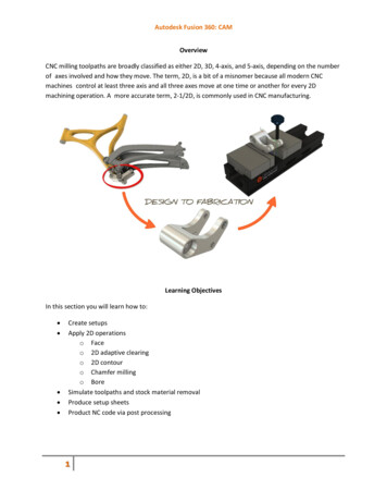
Autodesk Fusion 360: CAMOverviewCNC milling toolpaths are broadly classified as either 2D, 3D, 4-axis, and 5-axis, depending on the numberof axes involved and how they move. The term, 2D, is a bit of a misnomer because all modern CNCmachines control at least three axis and all three axes move at one time or another for every 2Dmachining operation. A more accurate term, 2-1/2D, is commonly used in CNC manufacturing.Learning ObjectivesIn this section you will learn how to: Create setupsApply 2D operationso Faceo 2D adaptive clearingo 2D contouro Chamfer millingo BoreSimulate toolpaths and stock material removalProduce setup sheetsProduct NC code via post processing1
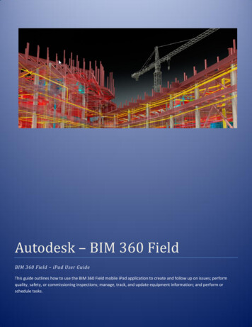
Autodesk Fusion 360: CAM2D vs. 3D Defined2D (Prismatic) Parts2-1/2D milling toolpaths machine only in the XY plane. The Z axis is used only to position the tool atdepth. The move to the cutting plane is a straight down feed, rapid, ramp or helical feed move.What do you mean by 2-1/2 axis programming? All cutting happens on the XY plane. Z is simply used toposition the tool to depth. We actually over-deliver, in that we support things like tracing a 3D path andthread milling.The term prismatic is a term commonly used in engineering to describe 2-1/2D parts. There are,however, prismatic parts that require 4 or 5 axis machining, so the term is used in machining onlyto describe parts where all machined faces lie normal to the machine tool spindle. The XY axes arenormal to the machine spindle and Z is used only to position the tool to depth (either in a feed orrapid motion).The image below shows a prismatic part. All machined features lie parallel to the XY plane. Each Zlevel is machined by positioning the tool at a fixed Z-level and then moving the XY axes to removematerial. Every feature can be reached with the tool approaching either from the Front or Bottomviews. There are several cutting planes in this example, including the model top (1), top of the facewhere the holes start (2), the bottom of the pocket (3) where the slots begin, the bottom of the slots(4), and the bottom of the hole through the center (5).2
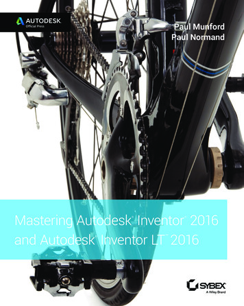
Autodesk Fusion 360: CAM3D Parts3D refers to non-prismatic parts, including molds and complex organic shapes. Most consumergoods, for example, include 3D features. The image below shows half of a stamping die. This part istypical in that it includes both 3D and 2D features. The 2D features are the top face (1), and the outsidecontour (2).3D features, like the revolved surfaces (3) and fillet (4), require more complex machine motion. Therevolved surfaces require XZ tool motion. The fillet requires XYZ tool motion. Even the flat (5) andcavity roughing (though technically planar) require 3D toolpaths because the adjacent revolvedsurfaces and fillet must be considered to prevent gouging the part. The calculations required tocalculate these toolpaths are highly complex.3
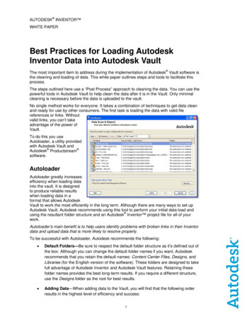
Autodesk Fusion 360: CAMDownhill mountain bike rocker armObjective: Use the CAM workspace in Fusion 360 and 2-1/2D axis milling techniques to fully machine theprovided part. This will require 3 job setups to machine the rocker arm.Using 2.5 Axis Functionality, we will begin with a block of Aluminum Stock mounted in a Vise (see Figure1), and will create three (3) ‘job setups’ that will be required to machine the Rocker Arm.4
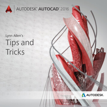
Autodesk Fusion 360: CAM1.1.2 Fixture Component TerminologyVise and AccessoriesThe CNC vise is precision engineered and manufactured with components ground flat andperpendicular to within .0002 inches. The most common is referred to as a six inch (6”) vise,because the width of the jaws is six inches.Once the vise is bolted to the table and aligned, parts are loaded into the vise and clampedby closing the jaws. The vise can exert tremendous force, so care is taken not to overtighten the vise and deform fragile parts. Vise pressure must be appropriate to the part beingheld and expected cutting forces.Vise StopFixed JawJaw InsertHard JawStep JawStandard 6-Inch ViseSoft JawThe Fixed Jaw remains stationary. The Moving Jaw opens when the Vise Handle is turned. It is agood practice to remove the vise handle after the jaws are closed and before running the program.This is done by sliding the handle off.A Vise Stop is a device that allows the parts to be loaded into the vise precisely. This image shows astyle of vise stop that is particularly useful because it is adjustable up-down and left-right.Hard Jaws are made of hardened steel and precision ground on all sides. They are usually used alongwith parallels.Parallels are thin steel plates, available in various widths, used to set the grip length of the vise jaws.5
Autodesk Fusion 360: CAMGrip LengthParallelHard JawStep jaws are similar to hard jaws but include a step feature that eliminates the need forparallels.Step6
Autodesk Fusion 360: CAMSoft jaws are blanks of aluminum used to grip parts that cannot be held using hard jaws. A cutout thesame shape as the part is machined into the soft jaws to grip irregular shapes.When machining the cutout, place a bar between the jaws to set the correct spacing. Use a torquewrench or mark the vise so it can be closed with the exact same pressure each time a new part isloaded. Remove the spacer before clamping the part.Mark Vise inPartCutoutIn Setup 1, we will:1. Setup up a Job2. Apply a multiple operations3. Visit the Tool Library4. Show Stock Simulation7
Autodesk Fusion 360: CAMIn Setup 2, we will:1.2.3.4.Setup up a new JobApply a multiple operationsVisit the Tool LibraryShow Stock SimulationIn Setup 3, we will:1.2.3.4.Setup up another JobApply a 2D Pocket OperationVisit the Tool LibraryShow Stock SimulationAfter all setups are created, we will create aSetup Sheet and output to a HAAS PostProcessor.8
Autodesk Fusion 360: CAMVertical Milling Center (VMC) Machine TerminologyColumn(Z)(Y)(X)TableCNC machines use a 3D Cartesian coordinate system. Figure 10 shows a typical.Material to be machined is fastened to the machine table. This table moves in the XY-Plane. As theoperator faces the machine, the X-Axis moves the table left-right. The Y-Axis moves the table forwardbackward.The machine column grips and spins the tool. The column controls the Z-axis and moves up-down.Work Coordinate System TerminologyTo make programming and setting up the CNC easier, a Work Coordinate System (WCS) isestablished for each CNC program.The WCS is a point selected by the CNC programmer on the part, stock or fixture. While the WCScan be the same as the part origin in CAD, it does not have to be. While it can be locatedanywhere in the machine envelope, its selection requires careful consideration.The WCS location must be able to be found by mechanical means such as an edge finder, coaxialindicator or part probe. It must be located with high precision: typically plus or minus .001 inches or less.It must be repeatable: parts must be placed in exactly the same position every time.It should take into account how the part will be rotated and moved as different sides ofthe part are machined.9
Autodesk Fusion 360: CAMThe image below shows a part gripped in a vise. The outside dimensions of the part have alreadybeen milled to size on a manual machine before being set on the CNC machine.The CNC is used to make the holes, pockets, and slot in this part. The WCS is located in the upper-leftcorner of the block. This corner is easily found using an Edge Finder or Probe.10
Autodesk Fusion 360: CAMSETUP 1Create the first setup: In this section, you go to the CAM workspace, create a setup, then set your stock.Step 1 – Open the design1. Open the Data Panel by clicking on the iconlocated at the top left of the menu bar. TheData Panel will slide open.2. Double-click 09 CAM for Fusion to open thedesign.LAUNCH VIDEO11
Autodesk Fusion 360: CAMStep 2 – Go to the CAM workspace1. Hover the mouse over the workspaceswitcher where it shows MODEL.2. Click CAM to switch to the CAM workspace.Step 3 – Verify the workspace1. You can tell which workspace is active bylooking at the toolbar. The toolbar shouldhave CAM commands listed.Step 4 – Orient the model1. Use the ViewCube or the navigationcommands to position the model as shown.12
Autodesk Fusion 360: CAMStep 5 – Create a setup and set the stock point1. Click Setup Setup.2. Select Stock Point.3. Click the upper stock point shown to movethe triad.4. Click the head of blue arrow to flip theorientation. We want the positive Z axisfacing up.5. Verify that the blue arrow (Z axis) is facing up,the green arrow (Y axis) is facing right, andthe red arrow (X axis) is facing towards you.Step 6 – Set the stock size1. Click the Stock tab.2. Set the Mode to Relative Size Box.3. Input these values:Stock Side Offset: 0.15 inStock Top Offset: 0.5 inStock Bottom Offset: 0.5 in4. Click OK.Step 7 – Finished setupYou have defined the size of the stock we will bemachining.13LAUNCH VIDEO
Autodesk Fusion 360: CAMToolpath OperationsToolpath OperationsUnderstanding Toolpaths by Type and UseBefore going further, it is helpful to understand how 2D toolpaths are classified in most CAM software.Please refer to the Autodesk CNC Handbook for more elaborate detail.FaceTypeToolpathFaceIsland Facing2D ContourContourChamferFilletPocketPocketSlot MillDrillDrill14Circular PocketMillingThread MillCommon Uses Finish face of part. Finish face with open sidesand bosses. Loops. Partial loops. Single edges. Stick (single point) fonts. Create dovetail, keyset, orsaw cut. Create chamfer usingtapered mill or center drill. De-burring. Creating fillet using CornerRound tool. Remove excess material. Machining TrueType(outlined) fonts and logos. Straight slot. Arc slot. Create spot drill, drill, tap,bore or reamed hole. Making holes greater than.75in diameter. Create ID threads over.75in diameter. Create milled OD threads ofany size.
Autodesk Fusion 360: CAM2D Machining Tab TerminologyTool: Defines the tool being used as well as the feeds and speeds.Geometry: Defines the geometry being machined.Heights: Controls heights the toolpath goes to such as cut depth and retract heights.Passes: Controls how the tool will go about removing material.Linking: Controls how the tool enters/exits and transitions between cutting movements.15
Autodesk Fusion 360: CAMFace Operation: In this exercise, you create a face operation.Step 1 – Start the Face command1. Click 2D Face.2. In the Face dialog box, click Select next toTool.LAUNCH VIDEOStep 2 – Windows library1. Select 2” Face Mill from the Tutorials (Inch)library.2. Click OK.The face operation automatically recognizes the topof the stock and machines down to the top of themodel.Step 2 – Mac library1.2.3.4.5.Check the Diameter box.Enter 2.0 in the field and click the link box.Select the 2” Face Mill.Click OK.Click OK to accept the tool post processorinformation.The face operation automatically recognizes the topof the stock and machines down to the top of themodel.16
Autodesk Fusion 360: CAMStep 3 – Finish the operation1. Click OK to create the face operation.Adaptive Clearing: Create an adaptive clearing operation to remove material around the outside of yourdesign.Adaptive clearing calculates paths based on a sophisticated algorithm that constantly considersthe remaining material and maintains optimal tool engagement throughout the cut. Since wekeep cut load constant, you can push the tool a lot faster and deeper through the material.”Step 1 – Start the 2D Adaptive Clearingcommand1. Click 2D 2D Adaptive Clearing.2. In the 2D Adaptive dialog box, clickSelect next to Tool.LAUNCH VIDEO17
Autodesk Fusion 360: CAMStep 2 – Windows library1. Select a Flat End Mill with:Diameter equal to 0.5 inFlute Length greater than 2 in2. Click OK.Step 2 – Mac library1. Check the box for Diameter.2. Enter 0.5 in the field and click the linkbutton.3. Check the box for Flute Length.4. Enter 2.5 in the field and click the linkbox.5. Select the ½” Flat tool.6. Click OK.7. Click OK to accept the tool postprocessor information.Step 3 – Select the geometry1. Select the Geometry tab.2. Select the top outside edge of thepart.Step 4 – Set the heights1. Select the Heights tab.2. Set the Bottom Height to Modelbottom.3. Under Bottom Height, set the Offsetto – 0.05 in.Machining past the part during roughinggives you a nice finish/transition when youface the backside.18
Autodesk Fusion 360: CAMStep 5 – Finish the operation1. Click OK to create the 2D AdaptiveClearing operation.Simulate the Toolpaths: Let’s simulate the two toolpaths that we have created so far. This gives you anopportunity to verify that the operations are set up the way you expect.Step 1 – Simulate the toolpaths1. In the browser, right-click on theSetup and select Simulate.2. In the Simulate dialog box, click theboxes for Toolpath, Stock, andTransparent.3. Click Play to see the simulation.4. After verifying stock simulation, clickClose.LAUNCH VIDEO19
Autodesk Fusion 360: CAM2D Contour: Create another 2D Contour. This is the finishing pass for this setup.Step 1 – Start the 2D Contour command1. Click 2D 2D Contour.2. CAM for Fusion 360 remembers thelast tool you used, so we will use the½” Flat End Mill for this operation.Step 2 – Select the geometry1. Select the Geometry tab.2. Select the same outside edge youselected for the 2D Adaptive Clearingoperation.The red arrow indicates the direction the toolwill follow either outside or inside the profile.In this example, the tool will follow on theoutside of the profile. Click the arrow to flipthe direction.Step 3 – Set the heights1. Select the Heights tab.2. Under Top Height, set From to Modeltop.3. Under Bottom Height, set From toModel bottom and enter – 0.025 infor the Offset.4. Click OK.20
Autodesk Fusion 360: CAMChamfer Mill Operation: Use a 2D Contour operation to chamfer the top edge of the part.Part 1 – Start the 2D Contour command1. Click 2D 2D Contour.2. In the 2D Contour dialog box, clickSelect next to Tool.LAUNCH VIDEOStep 2 – Windows library1. Use a 45 degree Chamfer Mill with a0.5 in Diameter.2. Click OK.Step 2 – Mac library1. Set the Operation to Chamfer.2. Check the Diameter box.3. Enter 0.5 in the field and click the linkbutton.4. Select the 1/2 “ chamfer mill.5. Click OK.21
Autodesk Fusion 360: CAMStep 3 – Select the geometry1. Select the Geometry tab.2. Select the same edge you selected inthe last two operations.Step 4 – Set the chamfer tip offset1. Select the Passes tab.2. The Chamfer option is presentbecause the tool is a chamfer mill.3. Set the Chamfer Tip Offset to 0.05 in.4. Click OK.The center of a spinning tool is not rotating asit is at the center of rotation. Instead, it isjust pushing material. By using a Tip Offsetthe tool slides down the chamfer and iscutting instead of pushing material resultingin a far better surface finish and avoiding thepossiblity of a step at the bottom of thechamfer.22
Autodesk Fusion 360: CAMBore operation: In this section, we will bore out four holes using two operations and two flat end millswith different diameters.Step 1 – Start the Bore command1. Click 2D Bore.2. In the Bore dialog, box click Selectnext to Tool.3. Select the same 1/2“ end mill used inthe 2D adaptive operation.LAUNCH VIDEO23
Autodesk Fusion 360: CAMStep 2 – Select the geometry1. Select the Geometry tab.2. Select the inside circular face shown.3. Click OK.Step 3 – Bore the other holes1. Right-click and select Repeat Bore.2. In the Bore dialog box, click Selectnext to Tool.Step 4 – Windows library1. Select a flat end mill with:Diameter equal to 0.25 in.Flute Length greater than 1.25 in.2. Click OK.24
Autodesk Fusion 360: CAMStep 4 – Mac library1. Check the box for Diameter.2. Enter 0.25 in the field and click thelink button.3. Check the box for Flute Length.4. Enter 1.75 in the field and click thelink button.5. Select the 1/4” flat tool.6. Click OK.7. Click OK to accept the tool postprocessor information.Step 5 – Select the holes1. Select the Geometry tab.2. Select the three holes3. Click OK.Step 6 – Simulate the setup1. In the browser, right-click on theSetup and select Simulate.2. In the Simulate dialog box, click theboxes for Toolpath, Stock, andTransparent.3. Click Play to see the simulation.4. After verifying stock simulation, clickClose.25
Autodesk Fusion 360: CAMSETUP 2In this setup, we will machine the Rocker Arm based off the orientation/position seen in below, and usea HAAS Vertical Milling Center (VMC) Machine. The work coordinate system (WCS) for Setup 2 will bedefined in upper right corner as well.Create Setup 2: Create the second setup and stock to continue machining the part.Step 1 – Orient the model1. Use the ViewCube or the navigationcommands to position the model asshown.26
Autodesk Fusion 360: CAMStep 2 – Create a setup and set the stockpoint1. Click Setup Setup.2. Select Stock Point.3. Click the upper stock point shown tomove the triad.4. Click the head of red arrow to flip theorientation. We want the positive Xaxis facing towards you.Verify that the blue arrow (Z axis) is facing up,the green arrow (Y axis) is facing right, andthe red arrow (X axis) is facing towards you.Step 3 – Set the stock size1. Click the Stock tab.2. Set the Mode to Relative Size Box.3. Input these values:Stock Side Offset: 0.15 inStock Top Offset: 0.5 inStock Bottom Offset: -1.5 in4. Click OK.27
Autodesk Fusion 360: CAMStep 4 – Finished setupYou have defined the size of the stock we willbe machining.The stock for Setup2 is shorter than in Setup1because what’s left to machine is theremainder of the material at the ‘bottom’ ofthe part; so there is no need to fully modelthe stock. Also, we won’t need to 2DAdaptive Clear the outside of the part, sincewe did that in SETUP 1.Face operation: Create a face operation and use the same face mill as in the previous face operation.Step 1 – Start the Face command1. Click 2D Face.2. In the Face dialog box, click Select next toTool.3. Select the same 2” Face Mill that was used inthe first face operation.4. Click OK to accept the tool.5. Click OK to create the operation.Step 2 – Face operation createdThe face operation is create for the second setup.28
Autodesk Fusion 360: CAMBore larger holes: Create a bore operation to machine the counterbores on two holes.Step 1- Start the Bore command1. Select 2D Bore.2. In the Bore dialog box, click Select next toTool.3. Select the 1/2” Flat Mill you used earlier.4. Click OK to accept the tool.Step 2 – Select the geometry1. Select the Geometry tab.2. Select the two cylindrical faces shown. Theseare the counterbores for the holes.3. Click OK to create the bore operation.29
Autodesk Fusion 360: CAMBore small holes: Create a bore operation to machine the two small holes.Step 1 – Start the Bore command1. Click 2D Bore.2. In the Bore dialog box, click Selectnext to Tool.3. Select the 1/4” Flat Mill tool usedpreviously.4. Click OK to accept the toolStep 2 – Select the geometry1. Select the Geometry tab.2. Select the two holes shown.3. Click OK to create the operation.30
Autodesk Fusion 360: CAMChamfer edge: Finish this setup by chamfering the edge of the part.Step 1 – Start the 2D Contour command1. Select 2D 2D Contour.2. In the 2D Contour dialog box, click Select nextto Tool.3. Select the same 1/2” Chamfer Mill usedearlier.4. Click OK to accept the tool.Step 2 – Select the geometry1. Select the Geometry tab.2. Select the edge of the part. Be sure to selectthe lower outer edge of the chamfer feature.3.Step 3 – Set the chamfer tip offset1. Select the Passes tab.2. The Chamfer option is present because thetool is a chamfer mill.3. Set the Chamfer Tip Offset to 0.05 in.4. Click OK.31
Autodesk Fusion 360: CAMStep 4 – Simulate the setup.1. In the browser, right-click on the Setup andselect Simulate.2. In the Simulate dialog box, click the boxes forToolpath, Stock, and Transparent.3. Click Play to see the simulation.4. After verifying stock simulation, click Close.SETUP 3In this setup, we will machine the Rocker Arm based off the orientation/position seen in the imagebelow, and use a HAAS Vertical Milling Center (VMC) Machine. The work coordinate system (WCS) forSetup 3 will be defined in the upper center.32
Autodesk Fusion 360: CAMCreate Setup 3: Create the second setup and stock to continue machining the part.Step 1 – Orient the model1. Use the ViewCube or the navigationcommands to position the model as shown.LAUNCH VIDEOStep 2 – Create a setup and set the stock point5. Click Setup Setup.1. Select Stock Point.2. Click the center stock point on the top faceas shown to move the triad.3. Click the body of blue arrow then select avertical edge to set the orientation. We wantthe positive Z axis facing up.Verify that the blue arrow (Z axis) is facing up, thegreen arrow (Y axis) is facing right, and the red arrow(X axis) is facing towards you.33
Autodesk Fusion 360: CAMStep 3 – Set the stock size1. Click the Stock tab.2. Set the Mode to Relative Size Box.3. Input these values:Stock Side Offset: 0 inStock Top Offset: 0 inStock Bottom Offset: 0 in4. Click OK.The stock offset values are set to zero. Since we onlyhave the open pocket left to machine, there is noneed to add material to the outside of the part.Step 4 – Finished setupYou have defined the size of the stock we will bemachining.Create Setup 3: Create the second setup and stock to continue machining the part.Step 1 – Start the Bore command1. Click 2D 2D Pocket.2. In the 2D Pocket dialog box, click Select nextto Tool.3. Select the 1/4” Flat Mill tool used previously.4. Click OK to accept the tool.34
Autodesk Fusion 360: CAMStep 2 – Select the geometry1. Select the Geometry tab.2. Select the edge shown then click the blueprofile preview that is displayed. This displaysthe mini toolbar.3. Click the Open contour button in the minitoolbar.LAUNCH VIDEOStep 3 – Select the profile.1. Select the edges shown. There are nine totaledges to select.2. Click the Accept current contour button inthe mini toolbar.35
Autodesk Fusion 360: CAMStep 4 – Verify the path1. The toolpath should look like the imageshown. If needed, click on the red arrow toflip the direction of the toolpath to machineinside the pocket.Step 5 – Set the passes1. Select the Passes tab.2. Unselect the Stock to Leave option.3. Click OK to create the operation.36
Autodesk Fusion 360: CAMThe setup is complete.Setup Sheet: The Setup Sheet command generates an overview of the NC program for the CNCoperator. It provides tool data, stock and work piece positioning; as well as machining statistics.Step 1 – Start the Setup Sheet command1. Select Setup1, hold Shift then selectSetup3. This selects all three setups.2. Right-click then select Setup Sheet.Step 2 – Specify the location1. Navigate to a location to save the filethen click Save.2. Click OK in the warning dialog box.37
Autodesk Fusion 360: CAMStep 3 – Setup sheet1. The Setup Sheet is displayed in yourdefault internet browser.2. Review the content then close yourbrowser when done.5.0 Post ProcessorA post processor is essentially a printer driver for CNC machines; a unique configuration filethat allows our Post Processor System to turn your programmed toolpaths into CNC programs(G-Code) that your machine control executes to cut parts.Fusion 360 comes with a standard library of "Posts". These library posts are included becausethey have been proven to make good parts using standard machine defaults. As the complexityof your setups increases, and you learn more about your CNC, you will probably wantmodifications made to one of these library posts that produce code in a particular way or withparticular options enabled. This requires a post edit. Autodesk has a dedicated PostDevelopment Team that while not working with machine tool vendors to produce morestandard library posts helps our Autodesk CAM Resellers and end-users with post requests.Post Processor: In this section, you post the CNC code from the three setups you created.Step 1 – Start the Post Process command1. Select the three setups in thebrowser.2. Right-click then select Post Process.38
Autodesk Fusion 360: CAMStep 2 – Configure settings1. Click OK in the warning dialog boxabout multiple WCS.2. Select haas.cps – Generic HAAS asthe Post Processor.3. Enter 1234 in the Program Numberfield.4. Click OK.5. Enter a name and click Save.Many machines, like the Haas, requireprograms to be a 4 digit number. So, thepost forces the users to use a program namethat the control will accept. If your controlwill accept another naming convention, likefull alpha-numeric program names, the postcan be easily modified.Step 3 – Review the code1. The G-Code is displayed in the editor.2. Close the editor and return to Fusion.39
CNC milling toolpaths are broadly classified as either 2D, 3D, 4-axis, and 5-axis, depending on the number of axes involved and how they move. The term, 2D, is a bit of a misnomer because all modern CNC machines control at least three axis and all three axes move