Transcription
September 2003INTRODUCTIONThe 2004 edition of the Atwood Water Heater Service Manual is a resource created tohelp service technicians identify Atwood product by serial number, diagnose serviceproblems and efficiently and effectively process warranty claims.In 2003, Atwood relocated the Switch, Thermostat and ECO that was installed on theback of combination 6 and 10 gallon Gas/Electric Water Heaters. A double switch isnow located inside the RV for convenience and a joint ECO and T-Stat is located onthe gas side of the water heater. This leaves only the relay and heating element on thebackside of the water heater.Each of the manuals within this series offers a general overview of the product as wellas more specific product information. For each product within the manual, you willfind model identification, recommended tools and equipment, a sequence ofoperation, warnings, annual maintenance procedures, parts and troubleshootingguides, warranty procedures, flat rate schedules, and replacement part referencecharts.Due to the rapidly changing personal computer revolution we have placedtroubleshooting information in a variety of places to make sure that the most accurateinformation is available. The best place to find the current information about Atwoodproducts is our website: www.atwoodmobile.com. At our website brochures may bedownloaded, trouble shooting guides reviewed and the latest information bulletins canbe read. In addition all Atwood Authorized Service Centers are listed on our site,accessible via an easy-to-use search system.Service for all Atwood products is handled out of our Rockford location. Should youhave any questions regarding our products or the information contained in thismanual simply dial 1-800-825-4328. Be sure to have the Model and Serial Number whenyou call.Atwood Service DepartmentDisclaimer: The data presented in this publication is obtained from the most reliable sources, and is believed to be accurate as of thedate of publication. Responsibility for typographical errors or omission of data cannot be assumed by the publishers.1
NOTESTHIS PAGE INTENTIONALLY LEFT BLANK2
TABLE OF CONTENTSAtwood Water HeatersAtwood Letter1Aftermarket Model Identification4Pilot ModelsQuestions5Model Number Explanation / Features6Recommended Tools & Equipment7Gas Thermostat Controls & Pilot Assemblies8Pilot Sequence of Operation9Pilot & Main Burner10Trouble Shooting Guide11Engine Heat Exchange System / Aftermarket Heating Elements12Bolt-In Heating Element, Thermostat & ECO / 110 VAC Trouble Shooting Wiring Schematic13Screw-In Heating Element, Thermostat & ECO / 110 VAC Trouble Shooting Wiring Schematic14Electronic Ignition ModelsQuestions15Model Number Explanation / Features16Recommended Tools & Equipment17DSI Sequence of Operation18Trouble Shooting Guide - Electronic Ignition19-20Information Guide - Intermittent Ignition21-22Potted Channel Circuit Boards / Thermal Cut Off Device / Thermostat23Wiring Schematics24General Water Heater InformationQuestions25Pressure Temperature Relief Valve / Water Heater Tank Corrosion / Atwood Clad Tank26Flushing Tank / Winterizing Instructions27Water Heater Terminology28Warranty29Warranty Procedures2930Return Goods Policy (RETURN ADDRESS)Flat Rate Schedule31Pilot Water Heater Parts Breakdown32-34Replacement Part ReferenceG10B, G10C / G610-3B, GH610-3 / G4SM / G6A-2, G6A-3, G6A-6, G6A-6P, G6A-7, G6A-7P / GC6A, GC6A-3,GC6A-6, GC6A-7 / GH6-3, GH6-6, GH6-7 / GC6AA-7, GC6AA-7P / GC6AA-8, GC6AA-8P / G610-3,GC10-1, GC10-2, GC10-2P / GC10A-2 / GC10A-2P / G10-1, G10-1P, G10-2, G10-2PElectronic Ignition Water Heater Parts BreakdownReplacement Part Reference35-37G610-3E, GH610-3E / GCH6-4E, GCH6-6E, / GC6A-7E / GC6AA-7E / GC6AA-8E / GC6AA-9E, GC6AA-10EG6A-2E, G6A-3E, G6A-4E, G6A-6E, G6A-7E, G6A-8E / G6A-3E, GH6-3E / GH6-4E, GH6-6E, GH6-7E,GH6-8E / GCH6A-7E, GCH6A-8E, GCH6A-9E / GCH6A-10E /GCH10A-2E, GCH10A-3E / GCH10-4E / G10-1E / GH10-2E, GH10-3E / GC10-1E, GC10-2E / GC10A-2E /GC10A-3E / GC10A-4EService Tank Kit Part NumbersMarine Water Heater Parts BreakdownAtwood Training Tapes and Manuals3839ORDER BLANK3
Aftermarket Gas Water HeatersIncludes Doors & Switches (when appropriate)G6A-7 ----------------------------------6 gal.GC6AA-8 ------------------------------6 gal.GC6AA-10E ----------------------------6 gal.GCH6A-10E ----------------------------6 gal.G6A-8E --------------------------------6 gal.GH6-7 ----------------------------------6 gal.GH6-8E --------------------------------6 gal.G10-2 ----------------------------------10 gal.GC10A-2 ------------------------------10 gal.G10-3E --------------------------------10 gal.GC10A-4E ----------------------------10 gal.GCH10A-4E --------------------------10 gal.w/pilotcombo w/pilotelectronic gas comboelectronic gas combo w/heat exchangeelectronicw/pilot, heat exchangeelectronic w/heat exchangew/pilotcomboelectronicelectronic comboelectronic combo w/heat exchangeMarine Water HeatersEHM6-4WFHX ------------------------4 gal.EHM6-SMFHX ------------------------6 gal.H6-FHX --------------------------------6 gal.EHM6-ATC ----------------------------6 gal.EHM6-SMSS --------------------------6 gal.EHM11-SSDHXT --------------------6 gal.EHM11-SMFHX --------------------11 gal.EHM11-SST --------------------------11 gal.H11-FHX ------------------------------11 gal.EHPM10 ------------------------------11 gal.EH-20 ----------------------------------20 gal.E20 ------------------------------------20 gal.marine, front heat exchange & special hook-upelectric marine w/heat exchangemarine specialmarine, heat exchange & temp. controlmarine, rear heat exchange & special hook-upmarine, stainless steel dual heat exchange tubeelectric marine w/heat exchangeelectric, heat exchange stainless steel tankmarine specialelectric marine w/special tubeelectric marine w/heat exchangeelectric marineMarine International Water HeatersEHM6-220-FHX ----------------------6 gal.EHM6-220SST ------------------------6 gal.EHM6-220-FHX ----------------------6 gal.EHM11-220 --------------------------11 gal.EHM11-220SST --------------------11 gal.EHM11-220SS-4WFHX ----------11 gal.EHM11-220SS-IMFHX ------------11 gal.EH20-220 ----------------------------20 gal.E20-220 ------------------------------20 gal.marine, heat exchange, 220 voltsmarine, heat exchange, 220 volts, stainless steel housingmarine, heat exchange, 220 volt, 1000 watt elementmarine, heat exchange, 220 voltsmarine, heat exchange, 220 volts, stainless steel housingmarine, heat exchange, w/special hook-upmarine, heat exchange, 220 volt, 1000 watt elementmarine, heat exchange, 220 voltsmarine, 220 voltsEuropean Water HeatersEURI6A-6E ----------------------------6 gal. International Electronic 3-bar valveEURIH6-6E ----------------------------6 gal. International Electronic w/heat exchangeEURICH6-6E --------------------------6 gal. International Electronic Combo w/heat exchange4
PILOT MODELSQUESTIONSThe following questions should be answered during this portion of the manual:· Are the Robertshaw and White Rodgers thermostat gas control valves inter-changeable?· What is the minimum gas pressure required for proper water heater operation?· Where on the water heater gas control can gas pressure be tested?· Can the pilot flame be adjusted?· What is minimum millivolt output of the thermocouple required for proper gas control operation?· How can you test a thermocouple?· How tight should the thermocouple connection be at the gas control?· What is an E.C.O., where is it located and what is its function?· What is a proper main burner air shutter adjustment?· What is the proper control and main burner alignment?· How can you easily check the calibration of a control?5
Atwood 6 and 10 gallon Pilot Water HeatersAtwood water heaters are designed and approved for use only in recreation vehicles (travel trailers, 5th wheels,motor homes, etc.). They are offered in two sizes: 6 and 10 gallon capacities.TYPE OF GAS IGNITION This unit is ignited outside of the trailer by a match, piezo ignitor or other ignition device. The watertemperature is adjustable at the thermostat control.EXPLANATION OF MODEL NUMBER:Pilot ModelsG CH6 AA -7PPilot RelightVersionType of heating element(GC A - bolt on, GC A A- screw in)Gallon capacity (6 or 10)Engine Heat ExchangeCombination gas and 110 VAC electricPropane GasNOTE: When replacing the element on a combination gas/110 VAC unit, always check the backof the heater for the type of element it has. It will either be a bolt-on or screw-inelement. They are no interchangeable.FEATURES All units operate on propane gas. A heat exchange option is available for motor homes. The water heater tank must have factory equippedheat exchange tubes welded on it already. They cannot be added later. A new water heater tank with thisoption is the only way to obtain this feature. Skin mounting allows the water heater to be hooked up with plumbing and electrical before the sidewall iserected. The tank has a clad aluminum lining that protects against corrosion and does not need to be replaced ona yearly or more frequent basis like anode rods do. A more detailed explanation of cladding is found in theback of this manual. 95% of all servicing can be done on the outside of the water heater. 110 VAC heating components are theexception since they are located on the back of the water heater inside the trailer. A flush flange is available for all models. This makes the access door flush with the trailer sidewall. There are multiple protection features in the form of a pressure-temperature relief valve, a limit switch inthe gas thermostat and an externally sealed combustion chamber. On combination water heaters, the gas mode and the 110 VAC heating mode can be operated at the sametime since each mode has its own thermostat. Both the six and ten gallon units have the lightest weight in the industry. On all trailers purchased after June 1, 1997 Atwood Limited Warranty is for a period of two years. Thisincludes all reasonable labor charges. We have 650 Service Centers throughout the United States.6
Recommended Tools and EquipmentU-Tube Manometer - This is the most accurate device for measuring gas pressure. If you use a dial-typemanometer, it should be calibrated periodically with this type of manometer.Thermostat Wrench - This tool allows for easier and safer removal of the gas thermostat control. Anadjustable version for different size controls is available through most RV distributors or you may fabricate onefrom angle iron. We do not recommend using a pipe wrench because it may damage the control causing it togo out of calibration.U-TUBE MANOMETERwith 1/8” pipe nippleTHERMOSTAT WRENCHFill ctionMulti-meter - This is the most versatile meter and will test AC voltage and continuity. A continuity test can beused to test for a blown E.C.O. on a gas control.Magnet Assembly Thermocouple Tester - This assembly can be obtained at an electronics or hardware store.This same assembly can also be removed from a Robertshaw control. It will verify if a thermocouple is good.For testing, screw a thermocouple into the tester, heat the thermocouple for 25 seconds and then press theplunger down. If the plunger pops up in less that 25 seconds, the thermocouple is faulty.MAGNET ASSEMBLY TO TESTTHERMOCOUPLEMULTI-METER TO TESTAC VOLTAGE AND CONTINUITYCommon Hand Tools - 1/8 and 1/4 nut drivers, open end wrenches, flat blade and Phillips screw drivers.Leak Test Solution - A solution that bubbles when applied to gas fittings or connections showing when a gasleak is present.7
Gas Thermostat Controls and Pilot AssembliesOnly two makes of gas controls have been used on our pilot model water heaters. They are the Robertshaw“Unitrol” and White Rodger (formerly Jade or ITT).The Robertshaw control came in two different sizes of gas inlets: 3/8 inverted flare and 3/8 N.P.T. Theinverted inlet control is no longer available. Therefore, the water heater gas line connection will have to bemodified to 3/8 N.P.T. in order to use the current Robertshaw control.The White Rodger control is the valve we are using on all production today. Formerly it had a 3/8 N.P.T.inlet. Now it is only available with a 1/4 inlet. This improvement eliminates the adapter fitting into the controlallowing the use of only a single 45 degree elbow (3/8 flare x 1/4 N.P.T.). If you are replacing a current 1/4 inlet model control with a earlier model 3/8 inlet control you may have in stock, the adapter fitting thatmates the control and elbow fitting is still available.Although the controls appear quite different in size, the White Rodger and Robertshaw control areinterchangeable. Their manifolds will both line up with the burner tube properly.Both controls have a port to test gas pressure through the valve. This can be accomplished by removing thecover screw and inserting a 1/8” pipe nipple. After attaching your manometer hose to this fitting, themanometer should register 10” W.C. through the valve while it is operating.ROBERTSHAW “UNITROL”WHITE RODGERS (JADE, ITT) 3/8 Inverted inlet 3/8 N.P.T. outlet3/8 N.P.T. outlet(no longer available)(no longer available) 1/4 N.P.T. inlet 3/8 N.P.T. inlet3/8 N.P.T. outlet(replaces all Robertshawand Jade controls)3/8 N.P.T. outletThere are two main pilot assemblies that you will encounter in the field.The first is an earlier model Robertshaw pilot assembly with a 1/4 pilot gas line that mounted on the leftside of the main burner.The current pilot is the Jade assembly with a 1/8 pilot gas line and it mounts on the right side of the mainburner.The Robertshaw pilot is no longer available and the Jade pilot must be substituted. When installing a Jadeassembly in place of a Robertshaw assembly, if there is not a location on the right side of the main burner tomount the Jade pilot, a new burner that has the proper mounting holes will have to be purchased.Note: The size of the gas line does not haveany affect on the size of the pilot flame. Onlythe gas pressure and pilot orifice regulate theheight of the pilot flame.JADEROBERTSHAW(obsolete, replace with Jade)8
Pilot Sequence of OperationONE SHOTE.C.O. 190 Temperature LeverGas Inlet11" W.C.PressureON/OFF Pilot KnobPilot FlamePilot Orifice (inside)ThermocoupleAir ShutterJADE CONTROL SYSTEMPILOT OPERATION Gas Pressure11 W.C. to control is necessary. Set with two gas appliances running. Gas Controlsupplies gas to pilot orifice when control ON/OFF pilot knob is held at pilot position. Pilot Orificemeters gas to heat thermocouple. Flame should be high enough to engulf thethermocouple. Thermocouplegenerates millivoltage to the gas control’s magnet assembly. Magnetwhen it receives 12 millivolts or more it allows gas to flow freely to pilot withoutholding pilot knob. E.C.O.passes millivolts through the gas control and back to thermocouple. Tripspermanently open if water temperature exceeds 190 F. MAIN BURNER OPERATION Gas Controlsupplies gas to main burner when control knob is set to “ON” position and thetemperature lever is set to desired temperature after pilot is lit. Main Burner Orificemeters gas through burner tube. Main Burnerpilot ignites gas when it reaches end of this tube. Flame height adjusted by sliding airshutter. Ideal setting is 1/4 way open (.20 ). Flame should be primarily blue witha trace of yellow. Temperature Knobsetting of knob determines burner cycle and water temperature. Temperature range is70 F - 140 F.9
Pilot and Main BurnerPilot AdjustmentOnly the gas pressure, gas valve and the pilot orifice regulate the height of the pilot flame. Early model gascontrols have a pilot adjustment screw, but this screw has very little effect on the pilot. The pilotadjustment has been removed from the current White Rodger control. The flame should be high enough toengulf the thermocouple at all times. A pilot flame any larger could blow the E.C.O. in the gas control. Thisis typically the result of enlarging the pilot orifice hole with a pin or similar item. For further correctivemeasures, refer to the trouble-shooting guide.Temperature LeverOn/Off Pilot KnobPilot FlameFlame SpreaderAir ShutterBurner TubeThermocoupleMain Burner AdjustmentThe gas pressure, air shutter cleanliness of the burner tube and orifice regulate the main burner flame. Themain burner flame should be mainly blue with a trace of yellow and fairly quiet. If it is not, adjust the gaspressure to 11 W.C., ensure that the main burner air shutter is 1/4 way open and verify that the mainburner flame spreader is square to the end of the main burner. For further corrective measures, refer to thetrouble-shooting guide.Gas Valvener TuberdeOrifice HolMain Bur(orientation found in water heater)Main Burner AlignmentThe manifold and main burner should be as perfectly aligned as possible. In other words, the gas valveshould be rotated at the same angle as the main burner tube. If it is not, rotate the gas control and/or theorifice holder so that the orifice disperses gas straight down the center of the burner tube. If the valve mustbe backed off any, check for water leaks at the coupling the control screws into before you operate thewater heater.10
Pilot Water HeaterTROUBLE SHOOTING GUIDEEffective: 5/26/98Guides are only intended for use on Atwood products by service technicians who have successfully completedAtwood training. This guide should be used in conjunction with the appropriate Instruction Manual provided with theproduct and any applicable Industry standards. This is not intended to be a complete list. Please direct questionsconcerning service of Atwood products to 800-825-4328 before proceeding.CAUSESOLUTIONPILOT OUTAGEGas pressure incorrect --------------------------Set pressure to a minimum of 11 W.C. with two or more appliances runningBlocked “U” tube --------------------------------Remove obstructionImproper main burner alignment --------------Re-align main burner and main burner orifice holder and gas valveImproper air adjustment ------------------------Adjust main burner air shutter approximately 1/4 openWeak thermocouple------------------------------Replace thermocouplePoor pilot flame ----------------------------------Clean or replace pilot orificeWeak gas control magnet ----------------------Replace gas controlDefective E.C.O. in control ----------------------Replace gas control and check the pilot flame. It should be high enough to engulfthe thermocouple at all times.PILOT OUTAGE WHEN BUTTON OR KNOB IS RELEASEDThermocouple not hot --------------------------Hold button or knob for 30 seconds before releasingThermocouple loose ----------------------------Tighten connection at gas controlWeak thermocouple------------------------------Replace thermocoupleWeak gas control magnet ----------------------Replace gas controlDefective E.C.O. in control ----------------------Replace gas controlMAIN BURNER WILL NOT IGNITEBlocked main burner orifice --------------------Clean or replace orificeMain burner flame spreader mis-alignment --Square flame spreader to end of main burnerBlocked main burner ----------------------------Remove blockageImproper air adjustment ------------------------Adjust main burner air shutter approximately 1/4 openBlocked “U” tube --------------------------------Remove blockageGas control out of calibration ------------------Replace gas controlERRATIC MAIN BURNER FLAMEImproper gas pressure --------------------------Set inlet pressure to a minimum of 11 W.C. with two or more appliances runningImproper air adjustment ------------------------Adjust main burner air shutter approximately 1/4 openPartial blockage of main burner ----------------Remove blockagePartial blockage of main burner orifice --------Clean or replace orificeFlame spreader misaligned----------------------Re-align spreader or replace main burnerBlockage in “U” tube ----------------------------Remove blockagePoor gas supply ----------------------------------Replace gas supplyExhaust grille blocked --------------------------Remove blockageImproper main burner alignment --------------Re-align main burner, main burner orifice holder and gas valveSMOKING AND SOOTINGGas pressure incorrect --------------------------Set pressure to a minimum of 11 W.C. with two or more appliances runningPoor gas supply ----------------------------------Replace gas supplyImproper pilot flame ----------------------------Clean or replace pilot orificeImproper air adjustment ------------------------Adjust main burner air shutter approximately 1/4 openFlame spreader mis-aligned --------------------Re-align or replace main burnerBlocked main burner ----------------------------Remove blockageImproper main burner alignment --------------Re-align main burner, main burner orifice holder and gas valveBlocked “U” tube --------------------------------Remove blockageINSUFFICIENT WATER TEMPERATURETemperature selector out of place--------------Re-set to desired positionBypass levers improperly positioned ----------Reposition leversImproper air adjustment ------------------------Adjust main burner air shutter approximately 1/4 way openPartial main burner blockage ------------------Remove blockageImproper main burner adjustment ------------Re-align main burner and main burner orifice holderFlame spreader mis-aligned --------------------Re-align or replace main burnerBlocked “U” tube --------------------------------Remove blockage11
Engine Heat Exchange SystemHeat Exchanger TubesCustomer supplied SAE 053 A type"E" hose clampor evuivalentAnnualar GroveHeat ExchangerTubesCoolant System Hose(5/8" dia. SAE 20R3or equivalent)Customersupplied teeThe engine heat exchange system allows a motor home to heat the water while traveling. This convenientoption allows you to arrive at your destination with hot water. Operating a pilot or electronic water heater ongas while in transit is a dangerous practice.This system consists of a U-shaped aluminum tube that is attached to the outside of the tank with welds. SAEhoses are attached to both ends of this tube and are spliced into the engine coolant system.When the engine is running, the hot coolant flows past the tank through this tube and by means of heattransfer through the welds, heating the water. The design of this system will not allow the water to reach aboiling point. It will typically heat the water to about 130 F. in about 2-3 hours of driving.Aftermarket Heating Elements WARNINGEXPLOSION / BURN INJURY Aftermarket heating elements can lack critical safety controls. Use of these devices can lead to an out of control heating of water tank and acatastrophic wet side explosion.YOU DO NOT NEED AN AFTERMARKET HEATING ELEMENT ON AN ATWOOD WATER HEATER. THE USE OF AFTERMARKET HEATINGELEMENT DEVICES MAY ALSO RESULT IN DAMAGE TO COMPONENTS OR WATER HEATER.Atwood’s written warranty states- “failure or damage resulting from any alteration to our water heater is the owner’s responsibility”. ANYALTERATION, LIKE THE ADDITION OF AN AFTERMARKET HEATING ELEMENT DEVICE, WILL VOID THE WARRANTY. When Aftermarket heating elements are insertedinto the drain plug, customers are more prone notto flush their tanks. Not flushing the tankaccelerates tank corrosion on both our pilot andelectronic ignition water heaters creating a situationwhere the tank may have to be replaced. THIS WILLBE A NON-WARRANTABLE SITUATION. Temperatures produced by these heating elementscan exceed the 190 F. limit of the ECO on pilot modelgas control valves. This gas control valve contains aone-shot ECO. When this ECO blows, the control iscompletely non-functional and must be replaced.THIS WILL BE A NON-WARRANTABLE SITUATION.12
BOLT-INHeating Element, Thermostat & ECO110VAC Trouble-ShootingWiring SchematicUPTemperatureAdjustment DialECORe-SetButtonHot Lead( 1 )-BLACKGround Lead( 3 )-GREENCommon Lead( 2 )-WHITESwitchBLACKGroundBLACKManual ResetHigh TemperatureLimit SwitchFixed ThermostatElementEarly model water heaters with 110 VAC heatingcapacity used a bolt-on heating element and a onepiece thermostat/E.C.O.In the case where the 110VAC portion of the waterheater is not heating water, the following diagnosticsteps and repairs should be investigated:This 110 VAC system has an adjustable rectangularthermostat that is surface mounted to the inner tankand retained by a steel clip. The temperature settingsare HI, MEDIUM, and LOW. If the thermostat ismaking unobstructed contact with the aluminum tankand it is set to the HI position, it should heat the waterto 130 F. It will take longer to heat a tank of water onelectric than gas.Turn POWER OFF to the appliance beforeremoving junction box cover.The heating element was changed in 1996 from1500W to 1400W bringing the amperage draw downto 12.7 amps and allowing more cushion for the15 amp circuit breaker that is normally placed in line.This change adds a few minutes to the heating time.There are 110 VAC aftermarket conversion kits beingoffered by distributors in which the heating element isscrewed into the tank where the drain plug is located.We do not offer such a kit. Our kit includes the tankwith the 110 VAC components already installed in it.Perform the following steps with POWER ON towater heater.1. Verify switch-A is in ON position.2. Insure there is 110VAC to the unit (measurevoltage across the black and white lead to theappliance with POWER ON). If none, trace wiringback and make appropriate wire repair.Perform the following steps with POWER OFF towater heater.3. ECO Re-set Button-D should be depressed.4. Check for continuity between screw-B and screwC of thermostat. If none, replace thermostat.5. If water is insufficiently hot, check ECO /Thermostat-E is on high.6. Verify a good wire connection between thermostatscrew-C and heating element screw-G. Correct ifnecessary.7. There should be continuity between heatingelement screw-G and screw-F. If none, element isbad and should be replaced. Do not over-tightenself-tapping screws when installing new element.8. Check for continuity between element screw-Gand flange of element. If there is, element hasshorted. Element should be replaced.9. Verify ground connection.NOTE: Heating element can be operated on an emptytank for a limited period of time before it self destructs.13
SCREW-INHeating Element, Thermostat & ECO110VAC Trouble-ShootingWiring SchematicUPGFB DCAHot Lead( 1 )-BLACKGround Lead( 3 )-GREENCommon Lead( 2 )-WHITESwitchBLACKGroundElementBLACKFixed ThermostatManual ResetHigh TemperatureLimit SwitchCurrent production water heaters with the 110 VACheating option use a screw-in heating element, aseparate pre-set thermostat and a separate ECO.When the 110VAC portion of the water heater is notheating water, the following diagnostic steps andrepairs should be investigated:The screw-in heating element is rated at 1400 wattsjust like the bolt-on element. It is an incalloy elementand can be run for a limited amount of time in a drytank without shorting out.Turn POWER OFF to the appliance before removingjunction box cover.Perform the following steps with POWER ON towater heater.1. Verify switch is in ON position.2. Insure there is 110VAC to the unit (measurevoltage across the black and white lead to theappliance with POWER ON). If none, trace wiringback and make appropriate wire repair.CAUTION: If the heating element is allowed to runwith a dry tank, allow the tank to cool down for 2-3hours before adding water. Adding water beforethe tank cools sufficiently could collapse the tank.The thermostat and ECO are pre-set surface-mounteddiscs. The thermostat is set at 140 F and is the samethermostat used on the gas side of the electronicignition water heaters. The ECO is a backupthermostat and will trip if the thermostat fails and thewater temperature exceeds 170 F.Perform the following steps with POWER OFF towater heater.3. Manual reset ECO high limit switch-A should bedepressed. Check for continuity betweenTERMINAL B and TERMINAL C of ECO.4. Check for continuity between TERMINAL D andTERMINAL E of thermostat. If there is none, replacethermostat.5. If water is insufficiently hot, insure thermostat isflush with tank.6. Verify a good wire connection between ECOTERMINAL-C and heating element TERMINAL-F.Correct if necessary.7. Check for continuity between heating elementTERMINAL-F and TERMINAL-G. If none, element is badand should be replaced. Do not over-tighten selftapping screws when installing new element.8. There should NOT BE CONTINUITY between elementscrew-G and flange of element. If there is, elementhas shorted. Element should be replaced.9. Verify ground connection.NOTE: Heating element can be operated on an emptytank for a limited period of time before it self destructs.14E
ELECTRONIC IGNITION MODELSQUESTIONSThe following questions should be answered during this portion of the manual:· What is minimum gas pressure for proper water heater operation?· Where on the gas solenoid valve can gas pressure be tested?· What is the minimum voltage needed for operation?· What is the proper wiring hook-up for the water heater circuitry?· Can the Circuit Board Tester be used on both Fenwal and Channel circuit boards?· How can the Circuit Board Tester be used to check a "flying lead" circuit board?· What conditions can cause tracks on the back of the circuit board to blow?· What is a proper main burner air shutter adjustment?· What is the function of the thermal cut-off?15
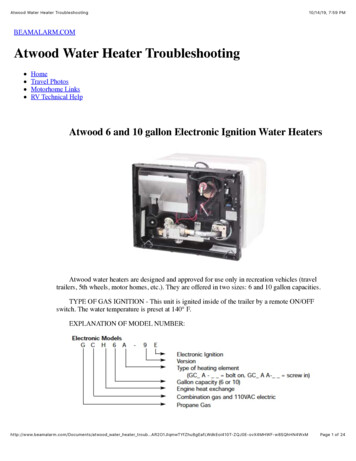
Atwood 6 and 10 gallon Electronic Ignition Water HeatersAtwood water heaters are designed and approved for use only in recreation vehicles (travel trailers, 5th wheels,motor homes, etc.). They are offered in two sizes: 6 and 10 gallon capacities.TYPE OF GAS IGNITION This unit is ignited inside of the trailer by a remoteON/OFFswitch. The water temperature is preset at 140 F.EXPLANATION OF MODEL NUMBER:Electronic ModelsG C H 6 A-9EElectronic IgnitionVersionType of heating element(GC A - bolt on, GC A A-
The 2004 edition of the Atwood Water Heater Service Manual is a resource created to help service technicians identify Atwood product by serial number, diagnose service problems and efficiently and effectively process warranty claims. In 2003, Atwood relocated the Switch, Thermostat and ECO that was installed on the .