Transcription
HYDRAULICS3BASIC LEVELMECHANICSAnAninitiativeof:of:initiative
HYDRAULICSTable of ContentsTRANSMISSIONS AND DRIVETRAIN1. Basic principles of hydraulics1.1 Additional component needed to run a Hydraulic System132. Control valve (4/3 valve)42.1 A Pressure Relief Valve42.2 The Pros and Cons of Hydraulics42.3 Two major Types of Hydraulic systems are used today52.4 Variations on Open and Closed Center Systems62.5 Control Valves82.6 Open Center System with Series Connection92.7 Open Center System with Series / Parallel Connection103. Hydraulic pumps 113.1 Positive Displacement pump 123.1.1 Fixed Displacement123.1.2 Variable Displacement 123.2 Types of Hydraulic Pumps 133.3 Axial Piston Pump (Variable Displacement) 143.4 Gear pumps 143.4.1 External Gear Pump 153.4.2 Internal Gear Pump 163.5 Vane pumps 173.5.1 Balanced vane pump 173.5.2 Unbalanced vane pump 183.6 Piston pumps 203.6.1 Axial Piston Pumps 203.6.1.1 In-line Axial Piston Pumps 213.6.1.2 Axial Piston Pump223.6.1.3 Bend-Axis Axial Piston Pump243.6.2 Radial Piston Pumps 253.7 Hydraulic Pump Efficiency 263.8 Pump Qualities263.9 Pump Delivery, Pressure and Speed 274. Safety 285. Hydraulic valves 295.1 IntroductionBASIC LEVEL MECHANICS 329
HYDRAULICS5.2 Pressure Control Valves 305.3 Relief Valves305.3.1 Direct Acting Relief Valves 305.3.2 Pilot Operated Relief Valves 325.4 Pressure Reducing Valves 335.5 Pilot Operated Types345.6 Pressure Sequence Valves355.7 Unloading Valves365.8 Unloading Valves for Accumulator Circuits 366. Hydraulic cylinders 376.1 Introduction376.2 Double Acting Cylinders406.3 Cushions (Hydraulic Buffer)416.4 Maintanance of Cylinders426.5 Bleeding Air from Remote Cylinders 436.6 Caution446.7 Basic Hydraulic System457. Hydraulic accumulators 467.1 Introduction467.2 Pneumatic Accumulators487.3 Bladder Type Accumulators487.4 Precautions507.4.1 Checking Precharged Accumulator on the Machine 507.4.2 Before Removing Accumulator from Machine 517.4.3 Repairing Accumulator517.4.4 Precharging Accumulator527.4.5 Installing Accumulator on Machine527.5 New Developments528. Practical Exercise53BASIC LEVEL MECHANICS 3
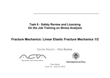
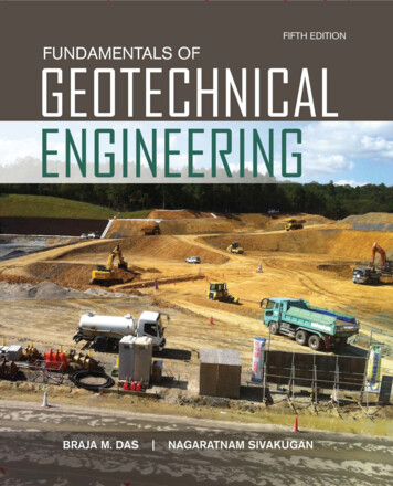
HYDRAULICS1. Basic Principles of HydraulicsTRANSMISSIONS AND DRIVETRAINThe basic principles of hydraulics are: Liquids have no shape of their own Liquids are practically incompressible Liquids transmit applied pressure in all directions Liquids provide great increases in work forceA) Liquids have no shape of their ownThey acquire the shape of any container. Because of this, oil in a hydraulic system will flowin any direction and into a passage of any size or shape.F 600 NA 5 Cm 2P FA 120 N / Cm 2B) Liquid transmit applied pressure in all directionsThe experiment in the glass jar will shatter the glass jar and also showed how liquidstransmit pressure in all directions when they are put under compression. This is veryimportant in a hydraulic system.A force of 600N on top of the cork will transmit a pressure of P 600 : 5 120 N/cm²This pressure is created throughout the system, and an equal force of 120N/cm2 is appliedto all the walls (and cork) of the jar.BASIC LEVEL MECHANICS 31
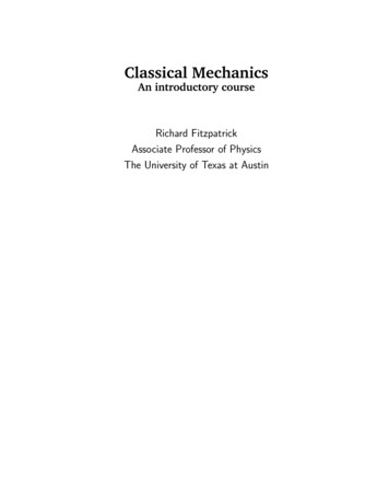
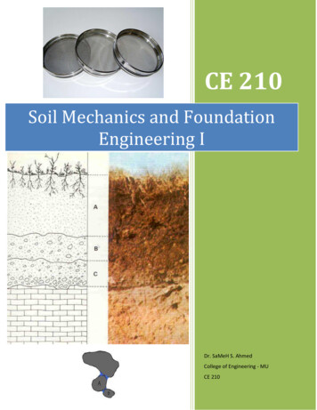
HYDRAULICSC) Liquids are practically incompressibleFor safety reasons, we obviously wouldn’t perform the experiment shown. However, ifwe were to push down on the cork of the tightly sealed jar, the liquid in the jar would notcompress. The jar would shatter first.Note: Liquids will compress slightly under pressure,but for our purposes they are incompressible.D) Liquids provide great increases in work forceLet’s take a bottle jack as an example.The pump plunger has an area of 7,07 cm2 andthe large lifting piston has an area of 314 cm2.Weight of the vehicle on the large piston is 1800kg1800 divided by 314 is 40,5 (kilo)Required force on the small plunger is 40,5 kilogram.A small force on the small plunger is able to lift a heavy load (1800kg)Letter:ABCDEFGDescription:Pump plunger with handlePomp-plunger (with small plunger area)Release valve (for lowering plunger D)Large pump plunger (lifting piston)Filler plug (oil)Hydraulic oilCheck valveFor transporting high oil pressures, special hoses are required, reinforced with metal layers.2BASIC LEVEL MECHANICS 3
HYDRAULICSTRANSMISSIONS AND DRIVETRAINPressure can be measured by using a manometer.How a hydraulic system worksA basic hydraulic system has two parts: A pump which transports the oil The cylinder or hydraulic motor which uses the moving oil to do work.In effect, the pump converts a mechanical force to hydraulic power, while the cylinderconverts the hydraulic power back to mechanical force to do work.1.1 Additional component needed to run a hydraulicsystem:A) Check valves: to hold the oil in the cylinders between strokes and to prevent oil fromreturning to the reservoir during the pressure stroke. The ball-type valves open when oil isflowing but close when the flow stops.B) A hydraulic tank (reservoir): to store the oil. If you keep on operating the pump to raisethe weight, a supply of extra oil is needed. The reservoir has an air vent which allows oilto be forced into the pump by gravity and atmospheric pressure when the pump piston isretracted.C) A control valve: directs the oil. This allows the operator to control the constant supplyof oil from the pump to and from the hydraulic cylinder. When the control valve is in theneutral position, the flow of oil from the pump goes directly through the valve to a linewhich carries the oil back to the reservoir. At the same time, the valve has trapped oil onboth sides of the hydraulic cylinder, thus preventing its movement in either direction.BASIC LEVEL MECHANICS 33
HYDRAULICS2. Control valve (4/3 way valve)2.1 A pressure relief valveBasically protects the system from high pressures. If the pressure required to lift the load istoo high, this valve opens and relieves the pressure by dumping the oil back to the reservoir.The relief valve is also required when the piston reaches the end of the stroke. At this timethere is no other path for the oil and it must be returned to the reservoir through the reliefvalve.2.2 The pros and cons of hydraulicsAs you have seen in the simple hydraulic system, we have just developed, the purpose is totransmit power from a source (engine or motor) to the location where this power is requiredfor work.To look at the advantages and disadvantages of the hydraulic system, let’s compare it tothe other common methods of transferring this power. These would be mechanical (shafts,gears, or cables) or electrical.A) Advantages1. Flexibility: Unlike the mechanical method of power transmission where the relativepositions of the engine and work site must remain relatively constant with the flexibility ofhydraulic lines, power can be moved to almost any location.4BASIC LEVEL MECHANICS 3
HYDRAULICSTRANSMISSIONS AND DRIVETRAIN2. Multiplication of force: In the hydraulic system, very small forces can be used tomove very large loads simply by changing cylinder sizes.3. Simplicity: The hydraulic system has fewer moving parts, fewer points of wear.And it lubricates itself.4. Compactness: Compare the size of a small hydraulic motor with an electric motor ofequal horsepower. Then imagine the size of the gears and shafts which would be requiredto create the forces which can be attained in a small hydraulic press. The hydraulic systemcan handle more horsepower for its size than either of the other systems.5. Economy: This is the natural result of the simplicity and compactness which providerelatively low cost for the power transmitted. Also, power and frictional losses arecomparatively small.6. Safety: There are fewer moving parts such as gears, chains, belt and electrical contactsthan in other systems. Overloads can be more easily controlled by using relief valves thanis possible with the overload devices on the other systems.B) Disadvantages1. Need for cleanliness: Hydraulic systems can be damaged by rust, corrosion, dirt, heatand breakdown of fluids. Cleanliness and proper maintenance are more critical in thehydraulic system than in the other methods of transmission.2.3 Two major types of hydraulic systems are usedtoday: Open-Center Systems Closed-Center SystemsA) Open Center SystemThe simple hydraulic system shown on page 4 is what we call an Open center system. Thissystem requires the control valve spool to be open in the center to allow pump flow to passthrough the valve and return to the reservoir. The pump we have used supplies a constantflow of oil and the oil must have a path for return when it is not required to operate a function.In the Closed center system, the pump is capable of “taking a break” when oil is notrequired to operate a function. Therefore, the control valve is closed in the center, whichstops (dead ends) the flow of oil from the pump-the “closed center” feature.BASIC LEVEL MECHANICS 35
HYDRAULICSFixed displacement pumps:are commonly used in combination with an Open center systemVariable displacement pumps:are commonly used in combination with a Closed center systemB) Closed Center SystemValve Stops Oil, But OilStays at Full SystemPressureThis Pump Can StopsPumping During NeutralTrapped OilHolds CylinderPiston in place2.4 Variations on Open- and Closed center systemsTo operate several functions at once, hydraulic systems have the following connections:A) Open center systems Open-Center with Series Connection Open-Center with Series Parallel Connection Open-Center with Flow DividerB) Closed center systems Closed-Center with Fixed Displacement Pump and Accumulator Closed-Center with Variable Displacement PumpA family of graphic symbols has been developed to represent fluid power components andsystems on schematic drawings. In the United States, the American National StandardsInstitute (ANSI) is responsible for symbol information. The Institute controls the make-up ofsymbols and makes changes or additions as required.6BASIC LEVEL MECHANICS 3
HYDRAULICSTRANSMISSIONSAND DRIVETRAINTheInternational StandardsOrganization (ISO) has the same control over symbols usedinternationally. Both systems have almost the same format (especially since ANSI changedits symbols in 1966 to eliminate all written information).Standard symbols allow fluid power schematic diagrams to be read and understood bypersons in many different countries, even when they don’t speak the same language. Eithersymbol set (ANSI or ISO) may be -- and is -- used in the United States.However, many companies today use the ISO symbols as their standard for work withforeign suppliers and customers. In order to simplify drawings of hydraulic systems, we willcontinue this book using ISO symbols.Instead of drawing complicated circuit diagrams, using pictures of original machinecomponents, hydraulic symbols are easy to draw and Internationaly recognisable asuniform language on hydraulic systems.Example:Number:12345Description:Hydraulic oil tank (reservoir)Suction filter (strainer)Hydraulic oil pumpHydraulic control valveHydraulic cylinder (double actingThe advantage of using symbols instead of pictures of original components, symbols aredesigned in such a way that the kind of valve can be recognised easily.Number 4 in the picture above, is a 4/3 way valve with open centre. The symbol has all theinformation you need to know what kind of valve it is.BASIC LEVEL MECHANICS 37
HYDRAULICS2.5 Control valvesControl valves can be operated by hand, by oil (servo) and electric (solenoid).The spool valve itself consists of a number of lands having slots “A” to meter the oil.The grooves labeled “B” are used as a kind of hydraulic bearing/seal.Spool slots are available in all kind of shapes, depending on the sensitivity required for eachparticular system.Solenoid operated valves are available in On / Off shifting valves and Proportional operatedvalves.8BASIC LEVEL MECHANICS 3
HYDRAULICS2.6 Open-Center System with Series ConnectionTRANSMISSIONS AND DRIVETRAINOil from the pump is routed to the two control valves in series.When the 1st valve is operated, no oil will reach the 2nd valve.In neutral, the oil passes through the valves in series and returns to the reservoir as shownby the arrows. When a control valve is operated, incoming oil is diverted to the cylinderwhich that valve serves.This system is satisfactory as long as only one valve is operated at a time. In this case thefull output of the pump at full system pressure is available to that function. However, ifmore than one valve is operated, the total of the pressures required for each individualfunction cannot exceed the system relief setting.BASIC LEVEL MECHANICS 39
HYDRAULICS2.7 Open-Center System with Series / ParallelConnectionThis system, shown below, is a variation on the series connected type. Oil from the pumpis routed through the control valves in series- but also in parallel. The valves are sometimes“stacked” to allow for the extra passages.In neutral, the oil passes through the valves in series as shown by the arrows.Valve 2 and 3 are a combination of series and parallel connection. When valve 2 is operated,valve 3 is also receiving oil and can be operated at the same time.10BASIC LEVEL MECHANICS 3
HYDRAULICS3. Hydraulic pumpTRANSMISSIONS AND DRIVETRAINThe pump is the heart of the hydraulic system. It creates the flow of fluid which supplies thewhole circuit.The human heart is a pump. So was the old water pump once found on the farm.Once the term “hydraulics” meant the study of fluids in motion. Therefore, any pump whichmoved fluids was considered a hydraulic pump.But today, “hydraulics” means the study of fluid pressure and flow-fluids in motion plus theability to do work.When is a pump hydraulicAll pumps create flow. They operate on a principle called displacement. The fluid is taken inand displaced to another point.Displacement can be done in two ways: Non-Positive Displacement Positive DisplacementBASIC LEVEL MECHANICS 311
HYDRAULICS3.1 Positive displacement pumpBut the positive displacement pump, used in hydraulics today, not only creates flow, it alsobacks it up. Notice the sealed case around the gear. This traps the fluid and holds it while itmoves.As the fluid flows out the other side, it is sealed against back-up. This sealing is the“positive” part of displacement. Without it, the fluid could never overcome the resistance ofthe other parts in the system.When high pressure is needed in a circuit, a positive displacement pump is a must. This istrue for all modern hydraulic systems which provide fluid power.In low-pressure systems, such as water cooling or crop spraying types, the old non-positivedisplacement pump still works.In this chapter, we will discuss only the positive displacement pump which is the heart ofmodern oil hydraulic systems. This pump is a true hydraulic pump.Displacement of hydraulic pump“Displacement” is the volume of oil moved or displaced during each cycle of a pump.In this sense, hydraulic pumps fall into two broad types: Fixed Displacement Pumps Variable Displacement Pumps3.1.1 Fixed displacementPumps move the same volume of oil with every cycle. This volume is only changed whenthe speed of the pump is changed.Volume can be affected by the pressure in the system, but this is due to an increasein leakage back to the pump inlet. Usually this occurs when pressure rises.This leakage means that fixed displacement pumps are usually found in lower pressuresystems or as aids to another pump in a higher pressure system.3.1.2 Variable displacementVariable displacement pumps can vary the volume of oil they move with each cycle-even atthe same speed. These pumps have an internal mechanism which varies the output of oil,usually to maintain a constant pressure in the system.12BASIC LEVEL MECHANICS 3
HYDRAULICSAND DRIVETRAIN TRANSMISSIONSWhen system pressuredrops, volume increases As pressure rises, volume decreases.Remember:A hydraulic pump does not create pressure: it creates flow.Pressure is caused by resistance to flow !3.2 Types of hydraulic pumpsNow that we have seen what hydraulic pumps are and what they can do, let’s take an“inside” look.a)b)BASIC LEVEL MECHANICS 313
HYDRAULICS3.3 Axial PistonPump (Variable Displacement)We will show how each type of pump operates and how it is used. A hydraulic system mayuse one of these pumps, or it may use two or more in combination.All three designs work on the rotary principle: a rotating unit inside the pump moves thefluid. A rotary pump can be built very compact, yet displace the necessary volume of fluid.This is the number one need in a mobile system where space is limited.3.4 Gear pumpsGear pumps are of the fixed displacement type. Two types being External gear type andInternal gear type. They are widely used because they are simple and economical. While notcapable of variable displacement, they can produce the volume needed by most systemsusing fixed displacement. Often they are used as charging pumps for larger system pumpsof other types. Servo systems also make use of gear pumps.Basic types of gear pumps are used: External Gear Pumps Internal Gear Pumps14BASIC LEVEL MECHANICS 3
HYDRAULICS3.4.1 External gear pumpTRANSMISSIONS AND DRIVETRAINExternal gear pumps usually have two gears in mesh, closely fitted inside a housingThe drive shaft drives one gear, which in turn drives the other gear. Shaft bushings andmachined surfaces or wear plates are used to seal in the working gears.OperationOperation is quite simple. As the gears rotate and come out of mesh, they trap inlet oilbetween the gear teeth and the housing. The trapped oil is carried around to the outletchamber. As the gears mesh again they form a seal which prevents oil from backing up tothe inlet. The oil is forced out at the outlet port and sent through the system.This oil is pushed out by the continuous flow of trapped oil coming into the outlet chamberwith each rotation of the gears. At the inlet side, gravity feeds in more oil from the reservoirto replace that drawn out by the turning gears.Some gear pumps use a pressurized plate working against the gears to increase pumpefficiency. A small amount of pressure oil is fed under the backing plate, pressing it againstthe gears and forming a tighter seal against leakage.BASIC LEVEL MECHANICS 315
HYDRAULICS3.4.2 Internal gear pumpThe internal gear pump also uses two gears, but now a spur gear is mounted inside a largergear. The spur gear is in mesh with one side of the larger gear, and both gears are dividedon the other side by a crescent-shaped separator. The drive shaft turns the spur gear, whichdrives the larger gear.OperationOperation is basically the same as for the external gear pump. The major difference is thatboth gears turn in the same direction.As the gears come out of mesh, oil is trapped between their teeth and the separator and iscarried around to the outlet chamber. As the gears mesh again, a seal is formed, preventingback-up of the oil. A continuous flow of oil to the outlet pushes the fluid out into the circuit.Gravity keeps feeding oil into the pump inlet to fill the partial vacuum created as oil isdrawn in by the gears.16BASIC LEVEL MECHANICS 3
HYDRAULICS3.5 Vane pumpsTRANSMISSIONS AND DRIVETRAINVane pumps are fairly versatile pumps and can be designed as single, double, or even tripleunits.All vane pumps move oil using a rotating slotted rotor with vanes fitted into the slots.Two types of vane pumps are most often used: Balanced Vane PumpsUnbalanced Vane PumpsThe balanced vane pump is strictly a fixed displacement type. The unbalanced vane canhave a fixed or a variable displacement.3.5.1 Balanced vane pumpsIn the balanced vane pump, the rotor is driven by the drive shaft and turns inside an ovalrotor ring.The vanes are fitted into the rotor slots and are free to move in or out.The “balanced” part of this pump is shown by the position of the oil ports. The pump hastwo inlet ports, located opposite each other. And it has two outlet ports, also on oppositesides of the pump. Both sets are connected to a central inlet and outlet.SlotInlet PortOutlet PortRotor RingInletOutlet PortVaneBASIC LEVEL MECHANICS 3Rotor17
HYDRAULICSOperationAs the rotor turns, the vanes are thrown out against the inside surface of the ring bycentrifugal force. As the vanes follow the contour of the oval-shaped ring, they divide thecrescent-shaped areas between the rotor and the ring into two separate chambers. Thesechambers are continually expanding and shrinking in size-twice during each revolution. Theinlet ports are located where each chamber begins to expand: the outlet ports are locatedwhere each chamber begins to shrink.As the chamber begins to expand, inlet oil rushes in to fill the partial vacuum. This oil iscarried around by the vanes. As the oil chamber begins to reduce, the confined oil is forcedout at the outlet port.In the second half of the revolution, this action is repeated at the second set of inlet andoutlet ports.3.5.2 Unbalanced vane pumpsThe unbalanced vane pump uses the same basic principle of a turning rotor with vanesworking inside a fixed rotor ring.18BASIC LEVEL MECHANICS 3
HYDRAULICSTRANSMISSIONSAND DRIVETRAINHowever,the operatingcycle only happens once each revolution. So this pump has onlyone inlet and one outlet port. Also, the slotted rotor is now set offside in a circular ring.In operation, the oil chamber starts to expand at the inlet port, and finishes its contractingat the outlet port.Oil is drawn in by the partial vacuum, and forced out by the shrinking of the chamber, thesame as in the balanced vane pump.However, the design of the unbalanced vane pump is different from the balanced type, aswe’ll explain now.Balanced vane pumps cannot operate as variable displacement pumps.Unbalanced pumps can be used as a variable displacement pump.The balanced vane pump is really a refinement of the unbalanced model. Why was thisrefinement needed?The unbalanced vane pump seemed to have frequent bearing failures. The cause was foundto be force on the shaft and bearings of the back pressure from oil being expelled at theoutlet side of the pump. No equal force was exerted on the opposite side, since the inlet oilwas under little or no pressure.The balanced vane pump was a solution to this problem. To balance off the outlet pressureson the shaft, two (2) outlet ports were used, directly opposite each other. his equalized theforces, increased bearing life, and made the pump work longer.While the balanced vane pump solved one problem, it posed another one: it could only beused for fixed displacement. The outlet port positions cannot be changed or the balancewould be upset.The unbalanced model can be used either for fixed or variable displacement. By specialdesign, the position of its rotor ring and oil ports can be changed in relation to the offset ofthe rotor. This changes the size of the chambers which the vanes create, thus the amount ofoil each carries. The result: a variable displacement pump.BASIC LEVEL MECHANICS 319
HYDRAULICS3.6 Piston pumpsPiston pumps are often favored on modern hydraulic systems which use high speeds andhigh pressures. However, piston pumps are more complex and more expensive than theother two types. Piston pumps can be designed for either fixed or variable displacement. Axial Piston Pumps Radial Piston Pumps3.6.1 Axial Piston pumpsAXIAL piston means that the pistons are mounted in lines parallel with the pump’s “axis” (aline down the center).RADIAL piston means that the pistons are set perpendicular to the pump’s center like thesun’s rays.Both styles of piston pumps operate using pistons which pump oil by moving back and forthin cylinder bores. (Another term for this movement is “reciprocate.”)Axial and radial piston pumps use reciprocating pistons but drive them by the rotaryprinciple. In this way the efficiency of the reciprocating method is combined with thecompactness of the rotary operating pump.The result is a pump which is efficient, yet can fit into a machine hydraulic system.Axial piston pumps usually fall into two broad types: inline and bent-axis.20BASIC LEVEL MECHANICS 3
HYDRAULICS3.6.1.1 In-line Axial Piston PumpsTRANSMISSIONS AND DRIVETRAINIn this pump, the cylinder block is mounted on a drive shaft and rotates with the shaft. Thepistons work in bores in the cylinder block which are parallel to the axis of the block. Theheads of the pistons are in contact with a tilted plate called a swashplate.The swashplate does not turn but it can be tilted back and forth. It mounts on a pivot and iscontrolled either manually or by an automatic “servo” device.Since the swashplate controls the output of the pistons, this pump has a variabledisplacement.Remember that the angle of the swashplate controls the distance that the pistons canmove back and forth in their bores. The greater the angle, the farther the pistons travel andthe more oil that is displaced by the pump.BASIC LEVEL MECHANICS 321
HYDRAULICSWhen the swashplate is tilted as shown. As the cylinder block rotates, piston bores alignwith this port and oil is forced into the bores by the small charging pump. This oil pushesthe pistons against the swashplate. Then as they revolve, these pistons follow the tilt of theswashplate and force the oil out of their bores into the outlet port.If the angle of the swashplate was fixed, the pump would operate as a fixed displacementtype, putting out the same amount of oil with each revolution.Swash PlateBend AxisThe bend axis shown above is of the fixed displacement type. It is often used as hydraulicmotor driving the tracks of hydraulic excavators.3.6.1.2 Axial piston pump22BASIC LEVEL MECHANICS 3
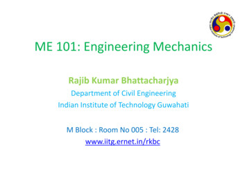
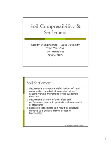
tion:123456789Port plate (inlet and outlet ports)Heavy coil springCylinder block (holding the pistons/plungers)Plungers (or pistons)Piston slippers retraction ringSwash plateServo controlled operation of swash plateBearings shells of swash plate (often needle bearing)Drive shaft of cylinder blockBASIC LEVEL MECHANICS 323
HYDRAULICSTo tilt the swashplate, the control lever is actuated, moving the displacement control valveto the left. This directs oil from the charging pump into the upper servo cylinder, moving thepiston which tilts the swashplate.Meanwhile the piston in the lower servo cylinder is pushed in by the lower part of theswashplate, forcing its oil back through the valve to the pump case.When the swashplate reaches the angle set by the control lever, the control valve returns toneutral and traps the oil in the servo cylinders. This holds the swashplate until the controllever is moved again.The pump keeps on pumping as explained before, drawing in oil at the top and pushing outoil at the bottom of each revolution.If the swashplate were tilted the opposite way, the inlet-outlet cycle of the pump wouldbe reversed. Oil would be drawn in at the bottom and pushed out at the top. So the servodevice not only controls the pump displacement but also the direction of this oil.3.6.1.3 Bend-Axis Axial Piston PumpAs explained earlier, the bend axis is a fixed displacement type of pump.Hydrostatic driven wheel loaders used to be equipped with bent axis hydraulic motors.Since more difference in speed and torque is needed, the latest type of wheel loaders areequipped with a axial piston pump, variable displacement, two directions of flow.The hydraulic motors are no longer of fixed displacement type but are variable and someWheel loader have two of them fixed onto the transfer box (high and low speed).24BASIC LEVEL MECHANICS 3
HYDRAULICSRadial piston pumpsTRANSMISSIONS AND DRIVETRAINRadial piston pumps are among the most sophisticated of all pumps. They are capable ofhigh pressures, high volumes, high speeds, and variable displacement.The basic operation is simple, but by using extra valves and other devices, this pump can beadapted to many systems and needs.This pump is closely fitted, so wear can be a problem unless clean oil is used. And the oilmust contain properties which lubricate the closely fitted parts.Radial piston pumps are designed to operate in two ways.In the “rotating cam” pump, the pistons are located in a fixed pump body. The center shafthas a cam which drives the pistons as it rotates.In the “rotating piston” pump, the pistons are located in a rotating cylinder. As the cylinderrotates, the pistons are thrown out against the outer housing. Since the rotating cylinder isset offside in the housing, the pistons are moved back and forth as they follow the housing.Excavators used to be equipped with Radial piston pumps.Today most heavy machinery and equipment use axial piston pumps.BASIC LEVEL MECHANICS 325
HYDRAULICSIn summary:1.2.3.4.5.6.A hydraulic pump converts mechanical force into hydraulic or fluid power-in otherwords, induces fluid to work.Of the two main types of pumps, positive displacement and non-positive displacement,the positive displacement type is best suited for power hydraulics due to its ability toproduce a steady flow against the high pressures in the system.A hydraulic pump can be designed to produce either a specific volume of fluid at a specificspeed, or to produce a variable volume of fluid at a constant speed . . . fixed displacementor variable displacement.The three types of pumps most often used in machine hydraulic Systems are gear, vane,and piston.These three pumps operate on a rotary principle. This allows them to be constructed assmall units, yet still have the ability to produce the required volume of fluid.The preceding text covers only basic hydraulic pumps and there are a great number ofvariations on all of the pumps selected.3.7 Hydraulic pump efficiencyThus far, we have only described the th
Basic principles of hydraulics 1 1.1 Additional component needed to run a Hydraulic System 3 2. Control valve (4/3 valve) 4 2.1 A Pressure Relief Valve 4 2.2 The Pros and Cons of Hydraulics 4 2.3 Two major Types of Hydraulic systems are used today