Transcription
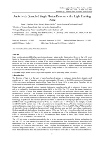
Modern Applied Science; Vol. 10, No. 1; 2016ISSN 1913-1844 E-ISSN 1913-1852Published by Canadian Center of Science and EducationAn Actively Quenched Single Photon Detector with a Light EmittingDiodeDavid J. Starling1, Blake Burger2, Edward Miller2, Joseph Zolnowski2 & Joseph Ranalli21Division of Science, Pennsylvania State University, Hazleton, USA2College of Engineering, Pennsylvania State University, Hazleton, USACorrespondence: David J. Starling, Penn State Hazleton, 76 University Drive, Hazleton, PA 18202, USA. Tel:1-570-450-3081. E-mail: starling@psu.eduReceived: September 10, 2015doi:10.5539/mas.v10n1p114Accepted: September 26, 2015Online Published: December 18, 2015URL: http://dx.doi.org/10.5539/mas.v10n1p114This research is financed by Penn State Hazleton.AbstractLight emitting diodes (LEDs) have applications in many industries for illumination. However, the LED is notlimited to the generation of light. In this article, we demonstrate and analyze a low-cost LED for use as a singlephoton detector, rather than as an emitter. While many technologies have been developed for single photondetection, the focus has been on timing resolution and efficiency—not on cost of production. We compare ourdevice to commercial solutions and validate the efficacy of active quenching to improve maximum photon countrate. While this device may be useful for labs requiring a large number of low-cost detectors, it can also serve asa teaching tool in advanced laboratory settings.Keywords: single photon detector, light emitting diode, active quenching, optics, electronics1. IntroductionThe detection of light is at the heart of many branches of science. In particular, single photon detection andcounting are key parts of quantum optics and communication (Divochiy et al., 2008), astronomy (Nightingale,1991), spectroscopy and general imaging (Tisa, Zappa, Tosi, & Cova, 2007), to name a few. Therefore, it is nosurprise that there currently exist a plethora of photon detection techniques.Dating back to the nineteenth century, chemical photography played a crucial role in astronomy for many years,only to be replaced by the charge-coupled device (CCD) in the 1970s. The CCD is now the standard technologyused in a variety of areas from amateur photography to scientific data collection. On the other hand, thephotomultiplier tube (PMT) was developed in the 1930s to provide higher sensitivity and timing resolution (butno spatial resolution). The PMT is capable of multiplying a faint light signal into a measurable fountain ofelectrons. More recently, semiconductor materials have outpaced the PMT as the primary single photon detectortechnology. In particular, the avalanche photodiode (APD) is capable of detecting single photons at a high rate(10 MHz) with very good timing accuracy (100 ps) and very low noise ( 100 Hz) (see, for example, Thorlabsmodel SPCM20A). Current state of the art systems have incorporated these APDs into 2-dimensional arrayscapable of detecting single photon images with high timing resolution (Tisa et al., 2007). The APD has a numberof drawbacks, however, including characteristically small detection areas and high bias voltage requirements.Modules capable of single photon detection, such as APDs and PMTs, are referred to collectively as singlephoton counting modules (SPCMs). In this article, we consider the use of the well-known light emitting diode(LED) as a possible alternative to the APD (Faramarzpour, Deen, Shirani, & Fang, 2008; Niclass, Sergio, &Charbon, 2006) to construct a low-cost SPCM.The LED has grown in popularity dramatically due to its low energy requirements for lighting applications; infact, the LED can even operate above unit efficiency by pumping heat from the environment into visible light(Santhanam, Gray, & Ram, 2012). However, it is not the lighting capabilities of the LED that we wish to explore.In the May 2013 issue of “The Relaxation Times”, a regular newsletter printed by TeachSpin, Inc., the authordescribed the possible use of a LED as a photon detector, rather than a photon emitter (What’s a SPAD?, 2013).From their experimental data, they demonstrated the linear response of the LED as well as its statistical behavior.114
www.ccsenet.org/masModern Applied ScienceVol. 10, No. 1; 2016In doing so, it was determined that the LED was behaving in a manner consistent with single photon detection,and even observed afterpulsing (i.e., a photon event triggering a second spurious avalanche of current), acommon characteristic of APD devices (Liu, Hu, Campbell, Pan, & Tashima, 2008).Based upon their results, we believe the LED has the potential for useful scientific photon measurements, albeitwith low detection efficiency. However, one common problem with diodes used for photon detection (includingLEDs) is the slow reset time of the circuit due to their internal capacitance; this slow reset limits the maximumachievable count rate. A typical strategy to combat this limitation with APDs is the inclusion of an active reset oran active quenching circuit (Cova, Longoni, & Ripamonti, 1982; Cova, Ghioni, Lacaita, Samori, & Zappa, 1996;Gallivanoni, Rech, Resnati, Chioni, & Cova, 2006; Zappa, Ghioni, Cova, Samori, & Giudice, 2000). However,there has been no work on an actively quenched LED SPCM. In the following sections, we demonstrate passiveand active quenching circuits using a LED for single photon detection.2. Method2.1 Method Background: LED vs. APDSemiconductor photon detectors use common features of the diode along with the conversion of light energy toelectrical current. A typical diode (e.g., Zener, APD, LED) is made up of two semiconductors placed in contactwith one another; see, e.g., Boylestad and Nashelsky (1996) and Plonus (2001). One of the materials is an n-typesemiconductor with electrons serving as the majority carrier. The other material is a p-type semiconductor withholes serving as the majority carrier. When these two materials are placed together, the electrons and holes nearthe junction combine in the depletion region. In this region, there are no majority carriers and so no substantialcurrent can flow through the diode.By applying a positive voltage to the p-type material (and negative to the n-type material), the holes andelectrons will move to fill in the depletion region, thereby allowing current to flow. This is the usualconfiguration for an LED, where photons are created via electroluminescence; i.e., when electrons and holescombine in the depletion region, their energy is converted to photons. However, if a negative voltage is appliedto the p-type material (and positive to the n-type material), the depletion region will only be further depleted ofmajority carriers and no current will flow. This is known as reverse bias and is the configuration used in photondetection.When a diode is placed in reverse bias, there is a point at which stray electrons within the material (known asminority carriers) are accelerated to sufficient speeds by the electrical potential that they can knock valenceelectrons from their covalent bonds. This has an avalanche effect, knocking out more and more electrons andproducing a large breakdown current. The voltage at which this occurs is known as the breakdown voltage orZener potential . While the avalanche is typically caused by the always present minority carriers, in the caseof the LED, the bias voltageis held below the Zener potential. In this case, the minority carriers do not haveenough energy to cause an avalanche. However, an avalanche can be produced by an electron knocked free viathe absorption of a single photon into the diode (i.e., the photoelectric effect). The high potential then acceleratesthe electron, potentially producing an avalanche as before.Figure 1. Passively quenched LEDA reverse-biased LED undergoing a photon-induced avalanche in the passively quenched configuration (shown115
www.ccsenet.org/masModern Applied ScienceVol. 10, No. 1; 2016in the inset). The exponential decay is due to the series resistance R and internal capacitance C of the LED (so). The 1/e decay time is11with an approximate series resistance of 100 kΩ.This process is possible due to the fact that an LED has the same basic structure as an APD, with a p-n junctionmade of two semiconductors. Despite this similarity, there are a number of key differences. In particular, theAPD has a very thick depletion region, improving photon absorption. In contrast, the LED has a very thindepletion region, resulting in better transparency and therefore good electroluminescence. However, the LED iscapable of photon absorption, and it is this feature we wish to exploit.2.2 Passive QuenchingIf a LED is placed in reverse bias near its breakdown voltage and a photon is absorbed, current begins to flow.However, once the current begins to flow, the resistance of the circuit will cause a drop in the bias voltage viaOhm's Law. This drop in potential reduces the acceleration of the electrons in the semiconductor. This behaviorpassively quenches the flow of electrons, eventually reseting the diode back to its original non-conducting state.This passive quenching circuit creates a reduction in the bias voltage in an exponential fashion, shown Figure 1.By monitoring the potential across the resistor, the current in the circuit resulting from a photon-inducedavalanche can be observed. The inset of the figure shows a circuit with the diode reverse-biased at approximately24 V along with a resistor to quench the avalanche. We use an encapsulated gallium arsenide phosphide (GaAsP)LED (model 276-041) with a 5 mm lens, forward bias operating parameters of 2.6 V, 28 mA, 10 mcd brightnessand a peak wavelength of 650 nm.We test the same LED using a variety of resistors between 11 kΩ and 100 kΩ. The decay time can be found/using a best fit curve of the formand the Pearson'stest as the fit parameter. We plot the decay timeas a function of resistance and find a linear relationship as shown in Figure 2.The minimum reverse bias voltage value found to produce avalanching behavior was22.2 V. By applyingmore voltage in excess of(seein Figure 3), the probability of an absorbed photon creating an avalancheincreases. However, this also produces an increased number of dark counts, the most common noise source forSPCMs. These unavoidable counts are caused by thermal excitation or minority carriers and add to photondetection events. However, they can be reduced in typical SPCMs using temperature control. We covered thedetector with an opaque shroud to measure dark counts, with results showin in Figure 3. In order to count thephoton detection events, the voltage output from the LED was passed to an ultrafast fast comparator (modelAD8561) to create square TTL pulses; the resulting pulses were sent to a custom FPGA pulse counter (NISTPhysical Measurement Laboratory, 2014).Figure 2. Reset time of LED SPCMThe decay time of a passively quenched LED at room temperature is shown as a function of the series resistanceof the circuit. The relationship is approximately linear with a slope of 0.102 0.002 s/kΩ. This implies thatthe capacitance of the LED is about0.102 nF.116
www.ccsenet.org/masModern Applied ScienceVol. 10, No. 1; 2016Figure 3. Dark counts of LED SPCMThe dark counts at room temperature for a passively quenched LED with an 81 kΩ resistor are shown as afunction of the applied excess bias voltage. The relationship is approximately linear with a slope of 3170 240Hz/V.2.3 Active QuenchingWhile the passively quenched circuit offers a simple solution to measure single photons, it is possible to expandthis analysis to more modern designs. State of the art semiconductor SPCMs have an active circuit that quicklylowers the bias voltage below the Zener potential of the APD. When this technique is applied to the LED SPCM,the drop in voltage prematurely ends the avalanche in a time significantly shorter than the passive decay time.Once the avalanche has ended, the bias voltage is returned to its original value to prepare the LED for anotherphoton detection event. A side effect of this process is that the maximum possible bias voltage applied to theLED is increased, resulting in more efficient detection than in the passively quenched design.In our design, the ultrafast comparator (C in Figure 4) switches on when a photon is detected. This signal triggersa metal-oxide-semiconductor field-effect transistor (MOSFET, T in Figure 4, model IRF510) to enter activemode, draining the source current through the 920 Ω resistor to ground and consequently lowering the biasvoltage applied to the LED. Once the voltage across the LED drops below a reference value, set by , thecomparator switches off and the MOSFET enters cutoff mode, thereby resetting the bias voltage to its originalvalue. The resulting avalanche current does not decay exponentially but is instead truncated in a time determinedby the response of the comparator and transitor. With this actively controlled circuit, we measured the maximumcount rate as a proxy for the exponential reset time.Finally, we characterized the response of the actively quenched LED SPCM to incident light. To do so, wemeasured the photon count rate and incident power produced by a HeNe laser, attenuated using rotated polarizers,as shown in Figure 4. The response is shown in Figure 5, and the results will be discussed in the followingsection.3. Results3.1 Passive QuenchingWe evaluated a standard low-cost LED for use as a SPCM in two configurations. In the passive configuration,we found that the LED has the characteristic behavior associated with photon avalanche events, includingexponential current decay, resistance-dependent reset time and dark counts that vary linearly with excess biasvoltage. In particular, it was possible to reduce the reset time to 1.56 s with an 11 kΩ resistor. This decay timesets the limit on the possible count rate R for the passively quenched configuration, given by1/640 kHz (compare to modern APD SPCMs with count rates above 10 MHz). This disadvantage can be partiallyovercome by employing active quenching.On the other hand, the minimum dark count rate was measured for the LED with an 81 kΩ resistor to be about500 Hz at room temperature. This value is comparable to many cooled APD SPCMs. However, at this largeresistance, the maximum possible count rate was limited.117
www.ccsenet.org/masModern Applied ScienceVol. 10, No. 1; 2016Figure 4. Active quenching experimental setupThe circuit diagram for the active quenching configuration (right) along with the experimental setup to measureis the bias voltage applied to the LED, andis the comparisonthe response (left) are shown. In the circuit,voltage used to trigger the comparator (C). The comparator produces a square pulse when the LED avalancheoccurs; this square pulse switches the MOSFET from cutoff mode to active mode, allowing the bias voltage todrain to ground through the 920 Ω resistor, reducing the voltage across the LED. Once the bias voltage drops(stopping the current through the LED), the comparator turns off so that the LED bias returns toand thedevice is ready to detect another photon. In the optical setup, the beam from a HeNe laser (L) passes through tworotation-mounted polarizersand . The power is adjusted using the polarizers and then measured with theLED SPCMand a calibrated power meterfor comparison.3.2 Active QuenchingThe actively quenched circuit was capable of measuring significantly higher count rates using the same resistorand LED combination when compared to the passive design. In particular, the LED with a 39 kΩ resistor had amaximum count rate of 10 kHz in the passive configuration, but 130 kHz in the active configuration (underidentical lighting conditions at room temperature). This behavior can be explained in part by the higher biasvoltages possible in the active configuration (before the LED ceases to avalanche). Additionally, the activequenching protects the LED from overheating by limiting the average current through the diode.While the reset behavior (delay and length) of the active circuit can be adjusted using faster electronics andvariable capacitors, we found that a straightforward design was sufficient to vastly increase the maximumpossible count rate. We obtained an increase in maximum count rate by a factor of 10 or more for the activequenching circuit when compared to passive quenching. Therefore, with suitable electronics, a rate of 6.4 MHz(a factor of 10 higher than the passive 640 kHz detector we tested) is expected. This rate is comparable tomodern commercial APDs.Using the actively quenched LED SPCM, we next tested its response to incoming light. From Figure 5, we seethat the detector responds nonlinearly. In particular, counts respond linearly in two regimes: below 20 µW andabove 100 µW, with a nonlinear transition between. This is likely the result of electronic delay or the long risetime of the transistor since this behavior was not exhibited in the passive design. Also, note that the incidentpower includes all spatial modes of the laser (captured by the calibrated power meter), while the LED onlycaptures a small fraction of these modes due to its size and orientation. For this reason, it is difficult toapproximate the efficiency of the SPCM.Despite the difficulty in determining the efficiency of detection, it is clear that the efficiency of the LED issignificantly lower than that of a traditional APD, most likely due to its small depletion region—both inthickness and in cross-section. However, commercially available LEDs with large cross-sections should alleviatedifficulties with light coupling. On the other hand, if one were to fabricate an LED with a thicker depletionregion, then the required bias voltage would increase and more specialized, high voltage equipment would berequired (as is the case with an APD SPCM).118
www.ccsenet.org/masModern Applied ScienceVol. 10, No. 1; 2016Figure 5. Response of Actively Quenched SPCMThe count rate response of the actively quenched LED at room temperature is shown as a function of incidentpower. Dark counts have been subtracted in this figure.4. DiscussionWe first explored the use of a LED as a SPCM in a passive circuit. This passive design introduced a variety ofkey considerations for detectors: max count rate, dark counts, afterpulsing, bias voltage, internal capacitance andresponse. We found that a LED can be used effectively as a SPCM, but was limited to sub megahertz count rates.From there, we expanded on this simple design to improve the maximum count rate. We found a factor of 10improvement was possible using a straightforward active quenching design. Therefore, we expect a detectionrate exceeding 5 MHz is possible with a low-cost LED.Using a LED as a SPCM has two key advantages in relation to APDs: they are inexpensive and plentiful, andthey can be used with standard and inexpensive electronic hardware at low voltages (less than 30 V). APDs, onthe other hand must be ordered or fabricated, often resulting in longer procurement times. Furthermore, mostsilicon APDs require more than 100 V (often over 200 V) to produce avalanching behavior and are equippedwith small solder points which add to experimental difficulty. Additionally, APDs tend to have very small activeregions, requiring high-numerical-aperture optics and careful alignment; conversely, large-area LEDs arecommon and affordable. For these reasons, the LED is a promising solution for research labs looking to employmultiple SPCMs at low cost.However, the detection efficiency of the LED SPCM is low enough that it is unlikely to find use in experimentsrequiring high efficiency, such as squeezing. However, with a large aperture LED and fast electronics, a LEDSPCM could be used for multimode detection with good timing resolution (Howland, Lum, Ware, & Howell,2013), shot noise limited power measurements or simply as an experimental tool for statistical analysis (Soares,Mendonca, & Ramos, 2014).It should be noted that the parameter space for experimentation and analysis is quite large. In this work, wefocused on improving the maximum count rate for practical applications. However, further study may include abetter characterization of the quantum efficiency of LEDs, active cooling to reduce dark counts or fine-tuning ofthe electronic components to reduce nonlinearities.AcknowledgmentsWe gratefully acknowledge the support from Penn State Hazleton and the College of Engineering, as well aswork conducted by Janak Jethva, Ryan Kanick, Thomas Klein and Richard Michael on an earlier version of theseexperiments.ReferencesBoylestad, R. L., & Nashelsky, L. (1996). Electronic devices and circuit theory (6th ed.). Columbus, OH:Prentice Hall.Cova, S., Ghioni, M., Lacaita, A., Samori, C., & Zappa, F. (1996). Avalanche Photodiodes and 5.001956119
www.ccsenet.org/masModern Applied ScienceVol. 10, No. 1; 2016Cova, S., Longoni, A., & Ripamonti, G. (1982). Active-Quenching and Gating Circuits for S.1982.4335917Divochiy, A., Marsili, F., Bitauld, D, Gaggero, A., Leoni, R., Mattioli, F., & Fiore, A. (2008). SuperconductingNanowire Photon-number-resolving Detector at Telecommunication Wavelengths. Nature Photonics, 2,302-306. our, N., Deen, M. J., Shirani, S., & Fang, Q. (2008). Fully Integrated Single Photon Avalanche DiodeDetector in Standard CMOS 0.18-µm Technology. IEEE Trans. on Elec. Dev., 55(3), allivanoni, A., Rech, I., Resnati, D., Ghioni, M., & Cova, S. (2006). Monolithic Active Quenching andPicosecond Timing Circuit Suitable for Large-area Single-photon Avalanche Diodes. Opt. Exp., 14(12),5021-5030. http://dx.doi.org/10.1364/OE.14.005021Howland, G. A., Lum, D. J., Ware, M. R., & Howell, J. C. (2013). Photon Counting Compressive DepthMapping. Optics Express, 21(20), 23822-23837. http://dx.doi.org/10.1364/OE.21.023822Liu, M., Hu, C., Campbell, J. C., Pan, Z., & Tashima, M. M. (2008). Reduce Afterpulsing of Single PhotonAvalanche Diodes Using Passive Quenching With Active Reset. IEEE J. of Quant. Elec., 44(5), iclass, C., Sergio, M., & Charbon, E. (2006). A Single Photon Avalanche Diode Array Fabricated in 0.35 µmCMOS and based on an Event-Driven Readout for TCSPC Experiments. Adv. Photon Counting Techniques6372, 63720S-12. http://dx.doi.org/10.1117/12.685974Nightingale, N. S. (1991). A New Silicon Avalanche Photodiode Photon Counting Detector Module forAstronomy. Exp. Astro., 1(6), 407-422. http://dx.doi.org/10.1007/BF00426721NIST Physical Measurement Laboratory. (2014). FPGA-based multicoincidence recipe and software. Retrievedfrom nce.cfmPlonus, M. (2001). Electronics and communications for scientists and engineers (1st ed.). New York, NY:Harcourt/Academic Press.Santhanam, P., Gray, Jr., D. J., & Ram, R. J. (2012). Thermoelectrically Pumped Light-Emitting tt.108.097403Soares, E. J. L., Mendonca, F. A., & Ramos, R. V. (2014). Quantum Random Number Generator Using Only .2014.2302436The Relaxation Times. (2013). What’s a SPAD? Retrieved from http://www.teachspin.com/newsletters/TeachSpin MAY13FINALFOR%20WEB.pdfTisa, S., Zappa, F., Tosi, A., & Cova, S. (2007). Electronics for Single Photon Avalanche Diode Arrays. Sensorsand Actuators A, 140(1), 113-122. http://dx.doi.org/10.1016/j.sna.2007.06.022Zappa, F., Ghioni, M., Cova, S., Samori, C., & Giudice, A. C. (2000). An Integrated Active-Quenching Circuitfor Single-Photon Avalanche Diodes. IEEE Trans. on Intru. and Meas., 49(6), ightsCopyright for this article is retained by the author(s), with first publication rights granted to the journal.This is an open-access article distributed under the terms and conditions of the Creative Commons Attributionlicense (http://creativecommons.org/licenses/by/3.0/).120
Keywords: single photon detector, light emitting diode, active quenching, optics, electronics 1. Introduction The detection of light is at the heart of many branches of science. In particular, single photon detection and counting are key parts of quantum optics and commu