Transcription
Chapter 6Polarization of LightWhen the direction of the electric field of light oscillates in a regular, predictablefashion, we say that the light is polarized. Polarization describes the directionof the oscillating electric field, a distinct concept from dipoles per volume in amaterial P – also called polarization. In this chapter, we develop a formalismfor describing polarized light and the effect of devices that modify polarization.If the electric field oscillates in a plane, we say that it is linearly polarized. Theelectric field can also spiral around while a plane wave propagates, and this iscalled circular or elliptical polarization. There is a convenient way for keepingtrack of polarization using a two-dimensional Jones vector.Many devices can affect polarization such as polarizers and wave plates. Theireffects on a light field can be represented by 2 2 Jones matrices that operate onthe Jones vector representing the light. A Jones matrix can describe, for example,a polarizer oriented at an arbitrary angle or it can characterize the influence ofa wave plate, which is a device that introduces a relative phase between twocomponents of the electric field.In this chapter, we will also see how reflection and transmission at a materialinterface influences field polarization. As we saw previously, s-polarized lightcan acquire a phase lag or phase advance relative to p-polarized light. This isespecially true at metal surfaces, which have complex indices of refraction. TheFresnel coefficients studied in chapters 3 and 4 can be conveniently incorporatedinto a Jones matrix to keep track of their influence polarization. Ellipsometry,outlined in appendix 6.A, is the science of characterizing optical properties ofmaterials through an examination of these effects.Throughout this chapter, we consider light to have well characterized polarization. However, most common sources of light (e.g. sunlight or a light bulb)have an electric-field direction that varies rapidly and randomly. Such sourcesare commonly referred to as unpolarized. It is common to have a mixture ofunpolarized and polarized light, called partially polarized light. The Jones vectorformalism used in this chapter is inappropriate for describing the unpolarizedportions of the light. In appendix 6.B we describe a more general formalism fordealing with light having an arbitrary degree of polarization.143Figure 6.1 Animation showingdifferent polarization states oflight.
144Chapter 6 Polarization of Light6.1 Linear, Circular, and Elliptical PolarizationConsider the plane-wave solution to Maxwell’s equations given byE (r, t ) E0 e i (k·r ωt )(6.1)The wave vector k specifies the direction of propagation. We neglect absorptionso that the refractive index is real and k nω/c 2πn/λvac (see (2.19)–(2.24)). Inan isotropic medium we know that k and E0 are perpendicular, but even after thedirection of k is specified, we are still free to have E0 point anywhere in the twodimensions perpendicular to k. If we orient our coordinate system with the z-axisin the direction of k, we can write (6.1) as ¡E (z, t ) E x x̂ E y ŷ e i (kz ωt )(6.2)As always, only the real part of (6.2) is physically relevant. The complex amplitudesof E x and E y keep track of the phase of the oscillating field components. Ingeneral the complex phases of E x and E y can differ, so that the wave in one of thedimensions lags or leads the wave in the other dimension.The relationship between E x and E y describes the polarization of the light.For example, if E y is zero, the plane wave is said to be linearly polarized along thex-dimension. Linearly polarized light can have any orientation in the x–y plane,and it occurs whenever E x and E y have the same complex phase (or a phasediffering by π). For our purposes, we will take the x-dimension to be horizontaland the y-dimension to be vertical unless otherwise noted.As an example, suppose E y i E x , where E x is real. The y-component of thefield is then out of phase with the x-component by the factor i e i π/2 . Taking thereal part of the field (6.2) we gethihiE (z, t ) Re E x e i (kz ωt ) x̂ Re e i π/2 E x e i (kz ωt ) ŷ E x cos (kz ωt ) x̂ E x cos (kz ωt π/2) ŷ E x cos (kz ωt ) x̂ sin (kz ωt ) ŷyxzFigure 6.2 The combination oftwo orthogonally polarized planewaves that are out of phase resultsin elliptically polarized light. Herewe have left circularly polarizedlight created as specified by (6.3).(left circular) (6.3)In this example, the field in the y-dimension lags behind the field in the xdimension by a quarter cycle. That is, the behavior seen in the x-dimensionhappens in the y-dimension a quarter cycle later. The field never goes to zerosimultaneously in both dimensions. In fact, in this example the strength of theelectric field is constant, and it rotates in a circular pattern in the x-y dimensions.For this reason, this type of field is called circularly polarized. Figure 6.2 graphically shows the two linear polarized pieces in (6.3) adding to make circularlypolarized light.If we view a circularly polarized light field throughout space at a frozen instantin time (as in Fig. 6.2), the electric field vector spirals as we move along the zdimension. If the sense of the spiral (with time frozen) matches that of a commonwood screw oriented along the z-axis, the polarization is called right handed. (Itmakes no difference whether the screw is flipped end for end.) If instead the field
6.2 Jones Vectors for Representing Polarization145spirals in the opposite sense, then the polarization is called left handed. The fieldshown in Fig. 6.2 is an example of left-handed circularly polarized light.An equivalent way to view the handedness convention is to imagine the lightimpinging on a screen as a function of time. The field of a right-handed circularlypolarized wave rotates counter clockwise at the screen, when looking along the kdirection (towards the front side of the screen). The field rotates clockwise for aleft-handed circularly polarized wave.Linearly polarized light can become circularly or, in general, elliptically polarized after reflection from a metal surface if the incident light has both s- andp-polarized components. A good experimentalist working with light needs toknow this. Reflections from multilayer dielectric mirrors can also exhibit thesephase shifts.6.2 Jones Vectors for Representing PolarizationIn 1941, R. Clark Jones introduced a two-dimensional matrix algebra that is usefulfor keeping track of light polarization and the effects of optical elements thatinfluence polarization.1 The algebra deals with light having a definite polarization,such as plane waves. It does not apply to un-polarized or partially polarized light(e.g. sunlight). For partially polarized light, a four-dimensional algebra known asStokes calculus is used (see Appendix 6.B).In preparation for introducing Jones vectors, we explicitly write the complexphases of the field components in (6.2) as³ E (z, t ) E x e i φx x̂ E y e i φy ŷ e i (kz ωt )(6.4)R. Clark Jones (1916 2004, American)was born in Toledo Ohio. He was oneof six high school seniors to receive aHarvard College National Prize Fellowship. He earned both his undergraduate(summa cum laude 1938) and Ph.D.and then factor (6.4) as follows:degrees from Harvard (1941). AfterE (z, t ) E eff³ A x̂ B e i δ ŷ e i (kz ωt )working several years at Bell Labs, he(6.5)spent most of his professional careerat Polaroid Corporation in CambridgeMA, until his retirement in 1982. Hewhereis well-known for a series of papers onpolarization published during the periodE eff q E x 2 2 E y e i φx E x (6.6)to the development of infrared detectors.He was an avid train enthusiast, andA q 2 E x 2 E y E y B q 2 E x 2 E y (6.7)δ φ y φx(6.9)even wrote papers on railway engineering. See J. Opt. Soc. Am.63, 519-522(1972). Also see SPIE oemagazine,p. 52 (Aug. 2004).(6.8)Please notice that A and B are real non-negative dimensionless numbers thatsatisfy A 2 B 2 1. If E y is zero, then B 0 and everything is well-defined. On the1 E. Hecht, Optics, 3rd ed., Sect. 8.12.2 (Massachusetts: Addison-Wesley, 1998).1941-1956. He also contributed greatly
146Chapter 6 Polarization of LightLinearly polarized along x·10 Linearly polarized along y·01 Linearly polarized at angle α(measured from the x-axis)· cos αsin αRight circularly polarized1p2·1 i Left circularly polarized1p2·1i Table 6.1 Jones Vectors for severalcommon polarization states.other hand, if E x happens to be zero, then its phase e i φx is indeterminant. In thiscase we let E eff E y e i φy , B 1, and δ 0.The overall field strength E eff is often unimportant in a discussion of polarization. It represents the strength of an effective linearly polarized field that wouldcorrespond to the same intensity as (6.4). Specifically, from (2.62) and (6.5) wehave11(6.10)I 〈S〉t nc²0 E · E nc²0 E eff 222The phase of E eff represents an overall phase shift that one can trivially adjust byphysically moving the light source (a laser, say) forward or backward by a fractionof a wavelength.The portion of (6.5) that is relevant to our discussion of polarization is thevector A x̂ B e i δ ŷ, referred to as the Jones vector. This vector contains the essentialinformation regarding field polarization. Notice that the Jones vector is a kindof unit vector, in that (A x̂ B e i δ ŷ) · (A x̂ B e i δ ŷ) 1. (The asterisk representsthe complex conjugate.) When writing a Jones vector we dispense with the x̂ andŷ notation and organize the components into a column vector (for later use inmatrix algebra) as follows:· A(6.11)B eiδThis vector can describe the polarization state of any plane wave field. Table 6.1lists some Jones vectors representing various polarization states.6.3 Elliptically Polarized LightIn general, the Jones vector (6.11) represents a polarization state between linearand circular. This ‘between’ state is known as elliptically polarized light. Asthe wave travels, the field vector makes a spiral motion. If we observe the fieldvector at a point as the field goes by, the field vector traces out an ellipse orientedperpendicular to the direction of travel (i.e. in the x–y plane). One of the axes ofthe ellipse occurs at the angleµ¶1 1 2AB cos δα tan(6.12)2A2 B 2with respect to the x-axis (see P6.8). This angle sometimes corresponds to theminor axis and sometimes to the major axis of the ellipse, depending on the exactvalues of A, B , and δ. The other axis of the ellipse (major or minor) then occurs atα π/2 (see Fig. 6.3).We can deduce whether (6.12) corresponds to the major or minor axis of theellipse by comparing the strength of the electric field when it spirals through thedirection specified by α and when it spirals through α π/2. The strength of theelectric field at α is given by (see P6.8)E α E eff pA 2 cos2 α B 2 sin2 α AB cos δ sin 2α(E max or E min ) (6.13)
6.4 Linear Polarizers and Jones Matrices147and the strength of the field when it spirals through the orthogonal direction(α π/2) is given byp(E max or E min ) (6.14)E α π/2 E eff A 2 sin2 α B 2 cos2 α AB cos δ sin 2αAfter computing (6.13) and (6.14), we decide which represents E min and whichE max according toE max E min(6.15)We could predict in advance which of (6.13) or (6.14) corresponds to the majoraxis and which corresponds to the minor axis. However, making this prediction isas complicated as simply evaluating (6.13) and (6.14) and determining which isgreater.Elliptically polarized light is often characterized by the ellipticity, given by theratio of the minor axis to the major axis:e E minE max(6.16)The ellipticity e ranges between zero (corresponding to linearly polarized light)and one (corresponding to circularly polarized light). Finally, the helicity orhandedness of elliptically polarized light is as follows (see P6.2):0 δ π left-handed helicity(6.17)π δ 2π right-handed helicity(6.18)6.4 Linear Polarizers and Jones MatricesIn 1928, Edwin Land invented an inexpensive polarizing device. He did it bystretching a polymer sheet and infusing it with iodine. The stretching caused thepolymer chains to align along a common direction, whereupon the sheet wascemented to a substrate. The infusion of iodine caused the individual chains tobecome conductive, like microscopic wires.When light impinges upon Land’s Polaroid sheet, the component of electricfield that is parallel to the polymer chains causes a current Jfree to oscillate inthat dimension. The resistance to the current quickly dissipates the energy (i.e.the refractive index is complex) and the light is absorbed. The thickness of thePolaroid sheet is chosen sufficiently large to ensure that virtually none of the lightwith electric field component oscillating along the chains makes it through thedevice.The component of electric field that is orthogonal to the polymer chainsencounters electrons that are essentially bound to the narrow width of individualpolymer molecules. For this polarization component, the wave passes throughthe material much like it does through typical dielectrics such as glass (i.e. therefractive index is real). Today, there is a wide variety of technologies for makingpolarizers, many very different from Polaroid.Figure 6.3 The electric field of elliptically polarized light traces anellipse in the plane perpendicularto its propagation direction. Thetwo plots are for different valuesof A, B , and δ. The angle α can describe the major axis (top) or theminor axis (bottom), dependingon the values of these parameters.
148Chapter 6 Polarization of LightArbitrary incidentpolarizationTransmission AxisA polarizer can be represented as a 2 2 matrix that operates on Jones vectors.2 The function of a polarizer is to pass only the component of electric fieldthat is oriented along the polarizer transmission axis. If a polarizer is orientedwith its transmission axis along the x-dimension, only the x-component of polarization transmits; the y-component is killed. If the polarizer is oriented withits transmission axis along the y-dimension, only the y-component of the fieldtransmits, and the x-component is killed. These two scenarios can be representedwith the following Jones matrices:·Transmitted polarizationcomponentFigure 6.4 Light transmittingthrough a Polaroid sheet. Theconducting polymer chains runvertically in this drawing, andlight polarized along the chainsis absorbed. Light polarized perpendicular to the polymer chainspasses through the polarizer.·1 00 0 0 00 1 (polarizer with transmission along x-axis) (6.19)(polarizer with transmission along y-axis) (6.20)These matrices operate on any Jones vector representing the polarization ofincident light. The result gives the Jones vector for the light exiting the polarizer.Example 6.1Use the Jones matrix (6.19) to calculate the effect of a horizontal polarizer onlight that is initially horizontally polarized, vertically polarized, and arbitrarilypolarized.Solution: First we consider a horizontally polarized plane wave traversing a polarizer with its transmission axis oriented also horizontally (x-dimension):·1000 ·10 · 10 (horizontal polarizer on horizontally polarized field)As expected, the polarization state is unaffected by the polarizer. (We have ignoredpossible attenuation from surface reflections.)Now consider vertically polarized light traversing the same horizontal polarizer. Inthis case, we have:· · · 1 000 (horizontal polarizer on vertical linear polarization)0 010As expected, the polarizer extinguishes the light.Finally, when a horizontally oriented polarizer operates on light with an arbitraryJones vector (6.11), we have·1000 ·AB eiδ · A0 (horizontal polarizer on arbitrary polarization)Only the horizontal component of polarization is transmitted through the polarizer.2 E. Hecht, Optics, 3rd ed., Sect. 8.12.3 (Massachusetts: Addison-Wesley, 1998).
6.4 Linear Polarizers and Jones Matrices149While you might readily agree that the matrices given in (6.19) and (6.20)can be used to get the right result for light traversing a horizontal or a verticalpolarizer, you probably aren’t very impressed as of yet. In the next few sections,we will derive Jones matrices for a number of optical elements that can modifypolarization: polarizers at arbitrary angle, wave plates at arbitrary angle, andreflection or transmissions at an interface. Table 6.2 shows Jones matrices foreach of these devices. Before deriving these specific Jones matrices, however, wetake a moment to appreciate why the Jones matrix formulation is useful.The real power of the formalism becomes clear as we consider situationswhere light encounters multiple polarization elements in sequence. In these situations, we use a product of Jones matrices to represent the effect of the compoundsystems. We can represent this situation by· 0 · AA Jsystem(6.21)B0B eiδwhere the unprimed Jones vector represents light going into the system and theprimed Jones vector represents light emerging from the system.The matrix Jsystem is a Jones matrix formed by a series of polarization devices.If there are N devices in the system, the compound matrix is calculated asJsystem JN JN 1 · · · J2 J1(6.22)where Jn is the matrix for the n polarizing optical element encountered in thesystem. Notice that the matrices operate on the Jones vector in the order thatthe light encounters the devices. Therefore, the matrix for the first device (J1 ) iswritten on the right, and so on until the last device encountered, which is writtenon the left, farthest from the Jones vector.When part of the light is absorbed by passing through one or more polarizersin a system, the Jones vector of the exiting light does not necessarily remainnormalized to magnitude one (see Example 6.1). The factor by which 0 2 the intensity 2¡ 0 ¡ 0 00 of the light decreases is given by A x̂ B ŷ · A x̂ B ŷ A B 0 . Theintensity exiting from the system is thenth 0 21 I 0 nc²0 E eff2where³ 0 2 E E eff 2 A 0 2 B 0 2eff(6.23)Here, E eff is the original effective field before entering the system (see (6.10)), and0E effis the final effective field.For the sake of further analysis, if desired, one can renormalize the final Jonesvector and write it in standard form as follows:· · e i φ A0à 0 A 0 00 p0 iδB̃ 0 e i δ A 0 2 B 0 2 B e0This is the Jones vector that is consistent with E eff. The uninteresting overalli φ A00phase factor ecan be incorporated into E eff , making à 0 real and positive. δ0 isthe phase difference between B 0 and A 0 .Linear polarizer·cos2 θsin θ cos θsin θ cos θsin2 θ Half wave plate· cos 2θsin 2θsin 2θ cos 2θQuarter wave platecos2 θ i sin2 θ (1 i ) sin θ cos θ(1 i ) sin θ cos θ sin2 θ i cos2 θ· Right circular polarizer12·1 ii1 Left circular polarizer· 1 1 i12 iReflection from an interface· r p00rsTransmission through aninterface· tp 00 tsTable 6.2 Common Jones Matrices. The angle θ is measured withrespect to the x-axis and specifiesthe transmission axis of a linearpolarizer or the fast axis of a waveplate.
150Chapter 6 Polarization of Light6.5 Jones Matrix for a PolarizerIncident LightTransmissionAxisIn this section we develop a Jones matrix for describing an ideal polarizer withits transmission axis at an arbitrary angle θ from the x-axis. We will do this in ageneral context so that we can take advantage of the present work when discussingwave plates in the next section. To help keep things on a more conceptual level,we revert back to using electric field components directly. We will make theconnection with Jones calculus at the end.The polarizer acts on a plane wave with arbitrary polarization. The electricfield of our plane wave may be written asTransmittedcomponentFigure 6.5 Light transmittingthrough a polarizer oriented withtransmission axis at angle θ fromx-axis.¡ E (z, t ) E x x̂ E y ŷ e i (kz ωt )(6.24)Let the transmission axis of the polarizer be specified by the unit vector ê1and the absorption axis of the polarizer be specified by ê2 (orthogonal to thetransmission axis). The vector ê1 is oriented at an angle θ from the x-axis, asshown in Fig. 6.6. We need to write the electric field components in terms of thenew basis specified by ê1 and ê2 . By inspection of the geometry, the x-y unitvectors are connected to the new coordinate system via:x̂ cos θê1 sin θê2ŷ sin θê1 cos θê2(6.25)Substitution of (6.25) into (6.24) yields for the electric fieldE (z, t ) (E 1 ê1 E 2 ê2 ) e i (kz ωt )whereE 1 E x cos θ E y sin θE 2 E x sin θ E y cos θFigure 6.6 Electric field components written in the ê1 –ê2 basis.(6.26)(6.27)Now we introduce the effect of the polarizer on the field: E 1 is transmittedunaffected, while E 2 is extinguished. To account for the effect of the device, wemultiply E 2 by a parameter ξ. In the case of the polarizer, ξ is zero, but when weconsider wave plates we will use other values for ξ. After traversing the polarizer,the field becomesEafter (z, t ) (E 1 ê1 ξE 2 ê2 ) e i (kz ωt )(6.28)We now have the field after the polarizer, but it would be nice to rewrite it in termsof the original x–y basis. By inverting (6.25), or again by inspection of Fig. 6.6, wesee thatê1 cos θx̂ sin θŷ(6.29)ê2 sin θx̂ cos θŷSubstitution of these relationships into (6.28) together with the definitions (6.27)
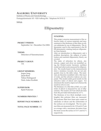
6.6 Jones Matrix for Wave Plates151for E 1 and E 2 yields ¡ ¡ Eafter (z, t ) E x cos θ E y sin θ cos θx̂ sin θŷ¡ ¡ ξ E x sin θ E y cos θ sin θx̂ cos θŷ e i (kz ωt ) ¡ E x cos2 θ ξ sin2 θ E y (sin θ cos θ ξ sin θ cos θ) x̂e i (kz ωt )¡ E x (sin θ cos θ ξ sin θ cos θ) E y sin2 θ ξ cos2 θ ŷe i (kz ωt )(6.30)Notice that if ξ 1 (i.e. no polarizer), then we get back exactly what we startedwith (i.e. (6.30) reduces to (6.24)).To get to the Jones matrix for the polarizer, we note that (6.30) is a linear mixture of E x and E y which can be represented with matrix algebra. If we representthe electric field as a two-dimensional column vector with its x component in thetop and its y component in the bottom (like a Jones vector), then we can rewrite(6.30) as·Eafter (z, t ) cos2 θ ξ sin2 θsin θ cos θ ξ sin θ cos θsin θ cos θ ξ sin θ cos θsin2 θ ξ cos2 θ ·ExEy e i (kz ωt )(6.31)Edwin H. Land (1909 1991, American)The matrix here is a properly normalized Jones matrix, even though we did notbother factoring out E eff to make a properly normalized Jones vector, as specifiedin (6.5). We can now write down the Jones matrix for a polarizer by inserting ξ 0into the matrix:· cos2 θsin θ cos θ(polarizer with transmission axis at angle θ) (6.32)sin θ cos θsin2 θwas born in Bridgeport Connecticut.Notice that when θ 0 this matrix reduces to that of a horizontal polarizer (6.19),and when θ π/2, it reduces to that of a vertical polarizer (6.20).what later would be called polaroid lm.He began college at Harvard University,but dropped out to work on his ideaof making an inexpensive polarizer. Hehad access to scienti c literature at NewYork Public Library. He gained accessto laboratory equipment by sneakinginto Columbia University after hours. Ina major breakthrough. Land inventedHe resumed his studies at Harvard, butnever graduated. This was in spite ofthe e orts of his wife who would extract answers from him and write up hishomework. A few years later, Land and6.6 Jones Matrix for Wave Platesa nancial backer formed Polaroid Corporation, which had tremendous successWe next consider wave plates (or retarders), which are usually made from birefringent crystals. The index of refraction in the crystal depends on the orientation ofthe electric field polarization. A wave plate has the appearance of a thin windowthrough which the light passes. The crystal is cut such that the wave plate hasa fast and a slow axis, which are 90 apart in the plane of the window. If thelight is polarized along the fast axis, it experiences index n fast . The orthogonalpolarization component experiences higher index n slow .When a plane wave passes through a wave plate, the component of the electricfield oriented along the fast axis travels faster than its orthogonal counterpart,which introduces a relative phase between the two polarization components.As light passes through a wave plate of thickness d , the phase difference thataccumulates between the fast and the slow polarization components isk slow d k fast d 2πd(n slow n fast )λvac(6.33)and growth thanks to Land's continuedinnovations over the years, includinghis development of an instant camera.Land would often work on a problem fordays without going home or changinghis clothes. He sometimes needed to bereminded to eat. (Wikipedia)
152Chapter 6 Polarization of LightBy adjusting the thickness of the wave plate, one can introduce any desired phasedifference.The most common types of wave plates are the quarter-wave plate and thehalf-wave plate. The quarter-wave plate introduces a phase difference ofk slow d k fast d π/2 2πm(quarter-wave plate) (6.34)between the two polarization components, where m is an integer. This meansthat the polarization component along the slow axis is delayed spatially by aquarter wavelength (or five quarters, etc.).The half-wave plate introduces a phase difference ofk slow d k fast d π 2πmSlow axisFast axisWaveplateTransmitted polarizationcomponents have alteredrelative phaseFigure 6.7 Wave plate interactingwith a plane wave.(half-wave plate) (6.35)where m is an integer. This means that the polarization component along theslow axis is delayed spatially by a half wavelength (or three halves, etc.). Whenm 0 in either (6.34) or (6.35), the wave plate is said to be zero order.The derivation of the Jones matrix for the two wave plates is essentially thesame as the derivation for the polarizer in the previous section. Let ê1 correspondto the fast axis, and let ê2 correspond to the slow axis, as illustrated in Fig. 6.7. Weproceed as before. However, instead of setting ξ equal to zero in (6.31), we mustchoose values for ξ appropriate for each wave plate. Since nothing is absorbed,ξ should have a magnitude equal to one. The important feature is the phase ofξ. As seen in (6.33), the field component along the slow axis accumulates excessphase relative to the component along the fast axis, and we let ξ account for this.In the case of the quarter-wave plate, the appropriate factor from (6.34) isξ e i π/2 i(quarter-wave plate) (6.36)This describes a relative phase delay for the light emerging with polarization alongthe slow axis. Substituting (6.36) into (6.30) yields the Jones matrix for a quarterwave plate:· cos2 θ i sin2 θsin θ cos θ i sin θ cos θsin θ cos θ i sin θ cos θsin2 θ i cos2 θ(quarter-wave plate) (6.37)For the half-wave plate, the appropriate factor applied to the slow axis isξ e i π 1and the Jones matrix becomes:· ·cos2 θ sin2 θ2 sin θ cos θcos 2θ 222 sin θ cos θsin θ cos θsin 2θ(half-wave plate) (6.38) sin 2θ cos 2θ(half-wave plate) (6.39)Remember that θ refers to the angle that the fast axis makes with respect to thex-axis.Before moving on, consider the following two examples that illustrate howwave plates are often used:
6.7 Polarization Effects of Reflection and Transmission153Example 6.2Calculate the Jones matrix for a quarter-wave plate at θ 45 , and determine itseffect on horizontally polarized light.Solution: At θ 45 , the Jones matrix for the quarter-wave plate (6.37) reduces to· e i π/41 i(quarter-wave plate, fast axis at θ 45 ) (6.40)p i12The overall phase factor e i π/4 in front is unimportant since it can be adjustedarbitrarily by moving the light source forwards or backwards through a fraction ofa wavelength.Now we calculate the effect of the quarter-wave plate (oriented at θ 45 ) operating on horizontally polarized light:· · · 111 i11 p(6.41)p102 i2 iThe linearly polarized light becomes right-circularly polarized (see Table 6.1)The previous example shows that a quarter-wave plate (properly oriented) canchange linearly polarized light into circularly polarized light. A quarter wave platecan perform the reverse operation as well. On the other hand, as seen in the nextexample, a half-wave plate can rotate the polarization angle of linearly polarizedlight by varying degrees while preserving the linear polarization.Example 6.3Calculate the effect of a half wave plate at an arbitrary θ on horizontally polarizedlight.Solution: Multiplying by the half-wave matrix (6.39), we obtain· · · cos 2θsin 2θ1cos 2θ sin 2θ cos 2θ0sin 2θ(6.42)The resulting Jones vector describes linearly polarized light at an angle α 2θ fromthe x-axis (see Table 6.1).6.7 Polarization Effects of Reflection and TransmissionWhen light encounters a material interface, the amount of reflected and transmitted light depends on the polarization. The Fresnel coefficients (3.20)–(3.23)dictate how much of each polarization is reflected and how much is transmitted.In addition, the Fresnel coefficients keep track of phases intrinsic in the reflection phenomenon. This is true also for reflections from multilayer coatings witheffective Fresnel coefficients (4.59), (4.60), (4.64) and (4.65).Figure 6.8 Animation showingeffects of polarizers and waveplates on polarized light.
154Figure 6.9 Incident, reflected andtransmitted plane waves, eachpropagating along the z-axis of itsown reference frame.Chapter 6 Polarization of LightTo the extent that the s and p components of the field behave differently,the overall polarization state is altered. For example, a linearly-polarized fieldupon reflection can become elliptically polarized (see L 6.9). Even when a wavereflects at normal incidence so that the s and p components are indistinguishable,right-circular polarized light becomes left-circular polarized. This is the sameeffect that ca
146 Chapter 6 Polarization of Light other hand, if Ex happens to be zero, then its phase ei x is indeterminant. In this case we let Eeff jEyjei y, B 1, and – 0. The overall field strength Eeff is often unimportant in a discussion of polariza- tion. It represents the strength of an effective linearly polarized fi