Transcription
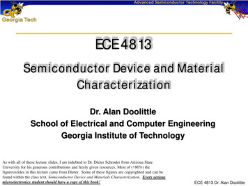
ECE 4813Semiconductor Device and MaterialCharacterizationDr. Alan DoolittleSchool of Electrical and Computer EngineeringGeorgia Institute of TechnologyAs with all of these lecture slides, I am indebted to Dr. Dieter Schroder from Arizona StateUniversity for his generous contributions and freely given resources. Most of ( 80%) thefigures/slides in this lecture came from Dieter. Some of these figures are copyrighted and can befound within the class text, Semiconductor Device and Materials Characterization. Every seriousmicroelectronics student should have a copy of this book!ECE 4813 Dr. Alan Doolittle
Optical CharacterizationOptical uminescenceECE 4813 Dr. Alan Doolittle
Optical ExcitationReflectionEmissionPhotoluminescence Raman Spectroscopy UV PhotoelectronSpectroscopy AbsorptionPhotoconductance PhotoelectronSpectroscopy hνOptical Microscopy Ellipsometry Reflection Spectroscopy TransmissionAbsorption Coefficient Infrared Spectroscopy ECE 4813 Dr. Alan Doolittle
Optical Characterization Photometric Measurements Amplitude of reflected or transmitted light Optical constants, absorption coefficientsECE 4813 Dr. Alan Doolittle
Optical Characterization Interference Measurements Phase of reflected ortransmitted light Film thickness, surfacestructure Two emerging light beams arephase shifted Constructive anddestructive interferenceλn1 sin φ ' n0 sin φd λ2 n12 n02 sin2 φφφPhaseShiftn0dn1φ'ECE 4813 Dr. Alan Doolittle
InterferenceConstructive InterferenceDestructive 0-2036912ωtEyeOxide thicknessvariationsECE 4813 Dr. Alan Doolittle
Interference Blue Morpho butterfly gets its brightblue color from interference effectsInterference due to microscopic ridgeson the wingsECE 4813 Dr. Alan Doolittle
Optical Characterization Polarization Measurements Ellipticity of reflected light Optical constants, film thickness, surface structurePolarizer polarizes the light into particular orientationH-sheet; most popular linear polarizer Polyvinyl alcohol (plastic sheet) is heated and stretched Sheet is dipped into iodine solution Iodine impregnates the plastic, attaches to long-chainmolecules, forms “wire” ticalpolarization,not transmittedECE 4813 Dr. Alan Doolittle
Polarized LightxElectric FieldyMagneticFieldzxxyyCircular Polarizationxx zyyElliptical PolarizationzECE 4813 Dr. Alan Doolittle
Polarizing Filter Effect Colored light from thin-filmiridescence in butterflies isoften polarizedLeft wings: unmodifiedRight wings: generated bytaking two photographsthrough a polarizing filterrotated by 90 between exposures,and then producing the differenceof the two imagesOne shows a pattern of polarizedand depolarized regions, the otherdoes notWing color important in male attraction to femalesA. Sweeney et al. Nature 423, 31 (2003)ECE 4813 Dr. Alan Doolittle
Diamonds What’s so special about diamonds?Star of SouthAfrica Diamond83.5 CaratsTaylor Diamond69 CaratsECE 4813 Dr. Alan Doolittle
Transmission, Reflection, Refraction A diamond is polished into a particular shape formaximum light refraction/reflection/transmission58 FacetsECE 4813 Dr. Alan Doolittle
Optical Microscopy Light cannot be focused to an infinitesimally small spot due tothe wave nature of lightECE 4813 Dr. Alan Doolittle
Optical Microscopy There is no lower limit to the size of anisolated object that can be detectedThe minimum separation, s, of twopoint objects occurs when the firstmaximum of the diffraction pattern ofone object falls on the first minimum ofthe second objects 0.61λ0.61λ n sinθNAλ free space wavelength,n refractive index of immersionmedium, θ half the angle subtendedby the lens at the object,NA numerical apertureBest resolution about 0.25 µmfor λ 0.4 µm, NA 1ECE 4813 Dr. Alan Doolittle
Optical Microscopy Different approaches to optical microscopybring out different featuresBright FieldDark FieldInterferenceContrastECE 4813 Dr. Alan Doolittle
Near Field Optical Microscopy Conventional microscopy Images the far field, where Raleigh limit prevailsNear field microscopy Images the near field, where solution determined byaperture, not wavelength Detector must be very close to sampleλλLensAperture λ D λ λ/2DetectorSphericallydivergingwaveSpacing DEvanescentwaveDetectorECE 4813 Dr. Alan Doolittle
Near Field Optical Microscopy The light is confined to a small aperture Drawn or etched glass fiberTopography Transmission FluorescenceLightAlCoatGlassFiberPolymer /nsom/nsom.htmlECE 4813 Dr. Alan Doolittle
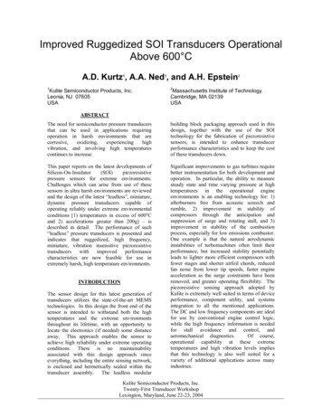
EllipsometryDefinition Measurement of the state of polarization of a polarized lightwaveGeneral Scheme A polarized light wave probe interacts with an "opticalsystem", this interaction changes the state of polarization,measurement of the initial and final states is performed thisyields information about the optical constants of the"system"ES EEPIncidentESEPReflectedECE 4813 Dr. Alan Doolittle
Null Ellipsometer Angles P, C, and A lead to ellipsometer quantities ρ, Ψand ρ tan Ψe j The ellipsometry EllipticallyPolarizedSampleECE 4813 Dr. Alan Doolittle
Ellipsometry Nondestructive techniqueFilm thickness measurement; can measure filmthicknesses down to 1 nmRefractive index determination; can measurerefractive index of thin films of unknown thicknessAzimuth angles can be measured with great accuracyMeasures a ratio of two values Highly accurate and reproducible (even in low lightlevels) No reference sample necessary Not as susceptible to scatter, lamp or purge fluctuations Surface uniformity assessmentComposition determinationsCan be used for in situ analysisECE 4813 Dr. Alan Doolittle
Ellipsometer Null ellipsometry Polarizer-Compensator-Sample-Analyzer Polarizer and Compensator Angles adjusted for linearpolarization upon reflection Analyzer is adjusted to extinguish reflected light Rotating Analyzer Ellipsometry Analyzer rotatesI (θ ) I0 [1 a2 cos 2θ b2 sin 2θ ]Ψ b2 1 cos 1( a2 ); cos 1 2 2 1 a2 Spectroscopic Ellipsometry Uses several wavelengths Can also use several anglesECE 4813 Dr. Alan Doolittle
Ellipsometry Measure change of polarization state of light reflectedfrom a surfaceRp E p (reflected )E (reflected ); Rs sE p (incident )E s (incident )ρ Rp tan Ψe j RsFor an air-solid with an absorbing substrate tan2 φ [cos2 2Ψ sin2 2Ψ sin2 ] n k n sin φ 1 [1 sin 2Ψ cos ]2 2121202n02 sin2 φ tan2 φ sin 4 Ψ sin 2n1k1 [1 sin 2Ψ cos ]2ECE 4813 Dr. Alan Doolittle
Transmission / AbsorptionDefinition Absorption - the loss of a photon from an incident flux by theprocess of exciting an electron from a lower- to a higher-energystateGeneral Scheme Light is incident on a thin sample part of the light is reflected andthe remainder is absorbed or transmitted; a measurement is madeof the transmitted intensityThe experiment can be carried out as a function of temperature,externally applied fields, sample thickness, etc.ItIidECE 4813 Dr. Alan Doolittle
Transmission Optical transmission measurements Sample thickness Absorption coefficient Impurities in semiconductors (oxygen and carbon in Si)R1AR2BIt1IiIr1Ir2(1 R1 )(1 R2 )e αdItT I i 1 R1R2e 2αd 2 R1R2 e αd cos φCFor R1 R2:DIt2n1, k1, αn00n0dT (1 R )2 e αd1 R 2e 2αd 2 Re αd cos φ(n0 n1 )2 k12R (n0 n1 )2 k12φ 4πn1dλxECE 4813 Dr. Alan Doolittle
TransmissionT 1T 2π 1 R 2e 2αd 2R e αd cos φπ(1 R )2 e αd π 1 R 2e 2αd 2 Re αd cos φ dφIf detector has insufficient resolutionT (1 R )2 e αd(1 R )2 e αd1 R 2e 2αdIf α 0T (1 R )2T1 R 2 2R cos φT (1 R )21 R2 1 R1 R1/λECE 4813 Dr. Alan Doolittle
Transmission Gives absorption coefficient, impurity density (e.g.,oxygen, carbon in Si), thickness21 (1 R ) α ln d (1 R )4 4T 2R 2 2T1;d 2n1 (1 λ ) ECE 4813 Dr. Alan Doolittle
Thickness Oscillations are determined bycos 4πnd / λ ; d Has maxima atmλ 0(m i )λi(m 1)λ1.d ;d 2n2n2n m d iλ iλo λi1λ0λii 2n(λ0 λi ) 2n(1/ λi 1/ λ0 )For i 1 : d (1/λ)1/λ: Wave number11 2n(1/ λ1 1/ λ0 ) 2n (1/ λ )ECE 4813 Dr. Alan Doolittle
Instrumentation Two types of instruments are ourceL1BeamSplitterDetector2φθNGratingExit SlitMovable MirrorSampleL2Fixed Mirrormλ 2d sin(θ)cos(φ)m 1, 2, 3 .;d line spacing of gratingECE 4813 Dr. Alan Doolittle
Interferometer Let source be cos2πfxSource f: frequency of light x: movable mirror location DetectorL1 L2 Constructive interference Maximum detector output L1BeamSplitterMovable MirrorSampleL2L1 L2 λ/4 Destructive interferenceFixed Mirror Zero detector outputL1 L2L1 L2 λ/4ECE 4813 Dr. Alan Doolittle
Fourier Transform Infrared SpectroscopyFourier transform infrared spectroscopy (FTIR)I ( x ) B(f )[1 cos 2πxf ]I (x ) f1 0I ( x ) 0 B(f )[1 cos 2πxf ]dffA cos 2πxf df Af1B(f ) sin 2πxf12πxf1ω ω I ( x ) cos 2πxf dx1Amplitude0.8(siny/y)2 f1f2Spectrumff1 103 cm-10.6 3x103 cm-10.40.20-0.001 -0.000500.0005 0.001x (cm)InterferogramECE 4813 Dr. Alan Doolittle
Interferogram - 61-464/ch362/irinstrs.htmECE 4813 Dr. Alan Doolittle
FTIR Applications Determine oxygenand carbon densityby transmission dipECE 4813 Dr. Alan Doolittle
Reflection Reflection measurements Film thickness Reflectivityr12e αd r22e αd 2r1r2 cos φ1R αde r12r22e αd 2r1r2 cos φ11111n0 n1n n2; r2 1n1 n2n0 n14πn1d 1 cos φ ′φ1 nr1 λ n0 sin φ n1 φ ′ sin 1 ECE 4813 Dr. Alan Doolittle
Reflection ExamplesRearview Mirrorhttp://sol.sci.uop.edu/ jfalward/refraction/refraction.htmlECE 4813 Dr. Alan Doolittle
Total Internal Reflection Snell’s law: n0sinθ0 n1sinθ1For θ1 θc sin-1(n0/n1) (critical angle) θ0 90 Total internal reflectionECE 4813 Dr. Alan Doolittle
Reflection R versus λ yields plotswith unequal wavelength spacingsR versus 1/λ(wavenumber) givesequal spacings0.3Reflectance iλ0 λ i2n1 (λi λo ) cos φ ′i 2n1 (1 λ0 1 λi ) cos φ ′i: number of complete cycles from λ0 to λi0.1Wavelength (cm)0.3Reflectanced1 0.20 00 10 2.5 10-5 5 10-5 7.5 10-5 1 10-42n d cos φ ′λ (max ) 1 1mm 1, 2, 3 λ 0 λ 1 λ2 λ3λ 3-1λ2-1λ1-1λ0-10.20.1005 1041 105 1.5 105 2 105Wavenumber (cm-1)ECE 4813 Dr. Alan Doolittle
Reflection FTIR Applications FTIR is used in may solid state and chemical E 4813 Dr. Alan Doolittle
Line Width Scatterometry uses scattered or diffracted lightFrom diffracted signature can determine Line height Line width Corner roundingVariable Variableθiθd Sidewall slope/angleSpecial test structureLight(variable λ)300SEM CD (nm)Detector2502001501003000 Measurements5050100150200250300Scatterometry CD (nm)C.J. Raymond in Handbook of Si Semiconductor Metrology(A.C. Diebold, ed.) Marcel Dekker, 2001.ECE 4813 Dr. Alan Doolittle
LuminescenceLuminescence is the emission of light due to: Incandescence: energy supplied by heatPhotoluminescence: energy supplied by lightFluorescence: energy supplied by ultraviolet lightChemiluminescence: energy supplied by chemicalreactionsBioluminescence: energy supplied by chemical reactionsin living beingsElectroluminescence: energy supplied by electriccurrent/voltageCathodoluminescence: energy supplied by electronbeams.Radioluminescence: energy supplied by nuclear radiationPhosphorescence: delayed luminescence or "afterglow"Triboluminescence: energy supplied by mechanical actionThermoluminescence: energy supplied by heatECE 4813 Dr. Alan Doolittle
Photoluminescence Incident laser creates electron-hole pairs (ehp)When the ehp recombine, they emit EAED-EVhν EGEVECE 4813 Dr. Alan Doolittle
How Does PL Work And How Can It Be Used? Carrier generation depth Wavelength depth informationRecombination Shockley-Read-Hall (impurities) impurity information Auger (high carrier densities) doping densityinformation Surface (surface states, impurities) surface information Radiative (light emission) detection mechanismThis is whatwe binationECE 4813 Dr. Alan Doolittle
Depth Dependent PL SignalsECE 4813 Dr. Alan Doolittle
Iron In Si by PL And PCDPLPCDMean: 175 µsDev.: 120 µsMean: 465 mVDev.: 7.74 mV450470Signal (mV)100FeMean: 2.4x1011 cm-3Dev.: 2.9x1011 cm-3200 300Lifetime (µs)4 6 1011 24 6NFe (cm-3)ECE 4813 Dr. Alan Doolittle
Review Questions What determines the resolution limit inconventional optical microscopy?What is near field optical microscopy?What are the basic elements of ellipsometry?How does FTIR work?Where are transmission measurements used?Where are reflection measurements used?What is luminescence?How can photoluminescence be used in Sicharacterization?ECE 4813 Dr. Alan Doolittle
Ellipsometry Definition Measurement of the state of polarization of a polarized light wave General Scheme A polarized light wave probe interacts with an "optical system", this interaction changes the state of polarization, measurement of the initial and final states is performed this yields i