Transcription
AutoCAD Structural Detailing 2011Getting Started with AutoCAD Structural Detailing,Reinforcement module
2010 Autodesk, Inc. All Rights Reserved. Except as otherwise permitted by Autodesk, Inc., thispublication, or parts thereof, may not be reproduced in any form, by any method, for any purpose.Certain materials included in this publication are reprinted with the permission of the copyrightholder.DisclaimerTHIS PUBLICATION AND THE INFORMATION CONTAINED HEREIN IS MADE AVAILABLEBY AUTODESK, INC. “AS IS.” AUTODESK, INC. DISCLAIMS ALL WARRANTIES, EITHEREXPRESS OR IMPLIED, INCLUDING BUT NOT LIMITED TO ANY IMPLIED WARRANTIESOF MERCHANTABILITY OR FITNESS FOR A PARTICULAR PURPOSE REGARDING THESEMATERIALS.TrademarksThe following are registered trademarks of Autodesk, Inc., in the USA and/or other countries:Autodesk Robot Structural Analysis, Autodesk Concrete Building Structures, Spreadsheet Calculator, ATC, AutoCAD,Autodesk, Autodesk Inventor, Autodesk (logo), Buzzsaw,Design Web Format, DWF, ViewCube, SteeringWheels, and Autodesk Revit.All other brand names, product names or trademarks belong to their respective holders.Third Party Software Program CreditsACIS Copyright 1989-2001 Spatial Corp. Portions Copyright 2002 Autodesk, Inc.Copyright 1997 Microsoft Corporation. All rights reserved.International CorrectSpell Spelling Correction System 1995 by Lernout & Hauspie SpeechProducts, N.V. All rights reserved.InstallShield 3.0. Copyright 1997 InstallShield Software Corporation. All rights reserved.PANTONE and other Pantone, Inc. trademarks are the property of Pantone, Inc. Pantone, Inc.,2002.Portions Copyright 1991-1996 Arthur D. Applegate. All rights reserved.Portions relating to JPEG Copyright 1991-1998 Thomas G. Lane. All rights reserved. Portions ofthis software are based on the work of the Independent JPEG Group.Portions relating to TIFF Copyright 1997-1998 Sam Leffler. Copyright 1991-1997 SiliconGraphics, Inc. All rights reserved.Government UseUse, duplication, or disclosure by the U.S. Government is subject to restrictions as set forth inFAR 12.212 (Commercial Computer Software-Restricted Rights) and DFAR 227.7202 (Rights inTechnical Data and Computer Software), as applicable.
ContentsGetting Started Guide . 1Getting Started . 1Exploring the User Interface. 1Object Inspector . 3Program Preferences . 5Types of Reinforcement . 6Rules for Positioning a Reinforcing Bar in a Drawing . 6Descriptions of Reinforcement. 7Workflow . 7Creating a Reinforced Concrete Structure . 8Creating a Template . 8Defining Formwork of a Beam. 12Adding Axes . 14Adding a Stirrup in the Cross‐Section . 15Adding a Stirrup in the Elevation View . 17Defining Main Bars . 20Creating Cross‐sections . 24Creating a Column and a Spread Footing . 30Adding Material Takeoffs . 34Definition of Views . 36Creating Sheets and Adding Views . 37
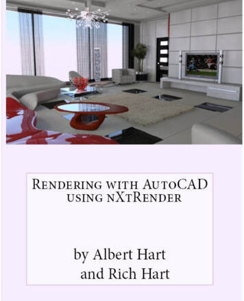
Getting Started GuideThank you for choosing AutoCAD Structural Detailing. The Reinforcement module is forautomated reinforcement definition and the generation of shop drawings for all types ofstructural concrete members. The exercises in this guide give you a starting point forpreparation of your own projects.Getting StartedBefore beginning the exercises, you need to install and register the software.AutoCAD Structural Detailing software comes with the AutoCAD Revit StructureSuite. This software is available for 32‐bit and 64‐bit Windows systems.Exploring the User InterfaceOpen AutoCAD Structural Detailing, Reinforcement module, and take a minute toview the different areas of the interface.RibbonAt the top of the interface is the standard Microsoft Windows element ‐ ribbon.The ribbon is an element of the user interface which replaces the traditional menuand toolbars and allows easy managing and adjusting the workspace. The ribbonconsists of several panels, grouped on tabs that are named by task or subject. Theribbon panels include many AutoCAD Structural Detailing commands that have beenon toolbars and in dialogs so far, such as icons, drop‐down lists, sliders, text fields andother elements characteristic of a given tab.NOTE It is possible to switch between workspaces (such as the classic workspace without theribbon). To do it follow one of the given methods:1 Click Manage h Customization h(User Interface) h in the Customize UserInterface dialog box select the Customize tab and in ASD/Workspaces select ASDReinforcement Classic h right‐click select Set current from the context menuh click Apply2 ClickReinforcement Classic.(at the bottom right corner of the screen) and select ASD1
Object InspectorInspector lets you manage elements (objects) included in a project that was created inAutoCAD Structural Detailing.Layout/Model Tab BarAt the bottom of the drawing area is the standard AutoCAD Model/Layout Tab Bar.There are 2 additional tabs defined – Edition Layout and Templates Layout. On theEdition Layout tab, you can modify the drawings (documents) generated for thestructure elements or group of elements. The Templates Layout tab displays theprintout templates defined in the project.RibbonObject Inspector2Model/Layout Tab BarModel/Drawing Area
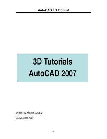
Object InspectorUsing the Inspector, you have quick access to project elements from every stage ofwork, which helps you manage your project. By default, the Object Inspector dialogdisplays on the left side of the interface, beside the drawing area. You can adjust thewidth of the dialog to leave as much space as possible for drawing the graphic model.On the Model tab is a list of model elements (levels, groups, and elements that belongto the levels and groups) that describe the division of reinforcing bars into structuralelements (beams, columns, spread footings, and so on).The Positions tab displays a list of defined views that contain the name, scale, andprintout layout name for the view.3
The Printouts tab lets you manage printouts in AutoCAD Structural Detailing. Itdisplays the list of all printouts and the associated views defined in the AutoCAD Structural Detailing project. The printout list includes all printouts, even those that donot contain views.Use the ASD Center tab to copy settings and styles between projects.4
Program PreferencesPreferencesThe Preferences are located in AutoCAD’s Options dialog. The Structural Detailing tablets you select the default start template and workspace name for the Reinforcementmodule. The software provides many templates that are defined for specificcountries.Job preferencesThese preferences are related to a particular template and project. After you havestarted working on a project, it is not possible to change work units. Some settings(such as design codes and databases) are specified only at the beginning of theproject, before you add elements into model space.5
Types of ReinforcementUsing the reinforcement module, you can create rebar or wire‐fabric for structuralelements of every type and shape (from beams to advanced, complicated elements).There are 3 ways to define reinforcement of structural elements: ManuallyAutomatically, based on macros for the generation of reinforcement andformwork of typical structures. Macros in AutoCAD Structural Detailing letyou generate complete concrete reinforcement drawings, together with rebardescriptions and material takeoffs.Using data from external software, by importing and exporting fromAutodesk Robot Structural Analysis Professional software, and by exportingreinforcement data from Revit Structure software.Rules for Positioning a Reinforcing Bar in a DrawingThe software determines the position of a reinforcing bar in a drawing depending onthe direction in which points are defined. The orientation of the reinforcing bar isdetermined by the order of the points in a clockwise direction, in relation to theexternal part of an object.6
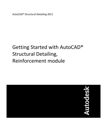
Descriptions of ReinforcementAfter reinforcement is defined (bar shape, reinforcement distribution, wire‐fabricdistribution, and so on), the software automatically runs an option that suggests adescription appropriate for the reinforcement type. The resulting dialog depends onthe type of selected reinforcement description.Every type of description has the Active option. If the option is on, then thereinforcement is described and is counted in the reinforcement table. When the samereinforcement is described twice, the option should be off to prevent doubling thenumber of reinforcing bars calculated when preparing a bar table.WorkflowThe creation of every complete project is based on 3 stages: Modeling ‐ you work on the Model tab (model space) to define formworks,reinforcement, and material takeoffs.Views – you work in model space to define each view as a single element with itsown scale.Printouts – you work in Layout space to prepare the final shop drawings. In thisstage, you work with views that were created earlier.ShopdrawingsModelingViews7
Creating a Reinforced Concrete StructureIn this lesson, you will create a simple reinforced frame and material takeoffs. You willalso create a final shop drawing.Creating a TemplateIn order to start working in AutoCAD Structural Detailing, you need to select atemplate. The template file contains initial, predefined settings of the workingparameters. In this exercise, you will create a template.1 Clickh New.2 In the Select template dialog, select RBCR‐044.dwt, and click Open.3 Define a new Bar table style:8 Click ASD ‐ Reinforcement h Settings h Styles ‐ reinforcementtables. Alternatively (for ASD Reinforcement Classic workspace),click Reinforcement menu h Reinforcement table h Styles ‐Reinforcement tables. In the Reinforcement tables ‐ style manager, for Table, select MAIN– bars, and then click New. On the Table tab of the Definition of new reinforcement table styledialog, select MAIN, and then clear Revision and select Bar symbol.
Click Select LENGTHS, and then select Total (bar). For Units, select m (meter), and specify the accuracy as 2 decimalplaces (0.00). Verify that Bar is selected, and specify the same settings. Click On the Sorting and detailed options tab, under Description of barsymbol, select Symbol: A, B, C. On the Options tab, select Automatically adjust row height. For List of styles, enter MyBarTableStyle as the name of the newstyle.9
Click OK. In the Reinforcement tables ‐ style manager dialog, for Table style,select MyBarTableStyle, and then click Default. Click OK.4 Change Job preferences:10 Click ASD ‐ Reinforcement h Settings h(Job preferences).Alternatively, click Reinforcement menu h Job preferences. In the left pane of the Job preferences dialog, select Bars h Display. Under Bar shape, for End of straight bars (without hooks), select thesecond option. In the left pane, select Codes / Materials. Under Reinforcing bars, for Database, click8666 2000 database. Under Reinforcing bars, for Steel grade R and T, change the Symbolto . Click OK.and select bar BS
5 Define an axis style: Click ASD ‐ Reinforcement h Settings h Graphic elements styles.Alternatively, click Reinforcement menu h Graphic elements hStyles ‐ graphic elements. In the Styles of symbols dialog, for Symbol, select Axis, and then clickNew. In the Axis dialog, under Axis, for Color, select Magenta. For Style name, enter MyAxisStyle, and then click Add. In the Styles of symbols dialog, for Symbol styles, selectMyAxisStyle, and then click Default. Click Close.11
6 Save the template:h Save as. Click For File name, enter MyTemplate.dwt, and click Save. In the Template Options dialog, click OK.7 Set your template as a default: Click ASD ‐ Reinforcement h Settings h(Preferences).Alternatively, click Reinforcement menu h Preferences. On the Structural Detailing tab of the Options dialog, forReinforcement, click Search. In the Open dialog, select MyTemplate.dwt, and click Open. In the Options dialog, click OK. Close the program.8 Proceed to the next exercise, Defining Formwork of a Beam.Defining Formwork of a BeamBefore you begin defining reinforcement for a beam, you should define its formwork.The formwork in the Reinforcement module can be created using Macros or usingAutoCAD options. In this exercise, you add the formwork of the beam into modelspace.1 Start the Reinforcement module of AutoCAD Structural Detailing:Click ASD ‐ Start h(Reinforcement).2 Click ASD ‐ Structure Elements h Structure elements ‐ formwork h(Beam). Alternatively, click Reinforcement menu h Formworks h Beam.3 In the Beam dialog, for Geometry tab, specify parameters of the beam’sformwork as shown.12
4 In the Beam dialog, for Sections tab, specify parameters of the beam’sformwork as shown.5 Click OK.6 In the drawing area, click to specify an insertion point.7 Remove axes at the beam’s support by using AutoCAD Erase option.8 Modify height of beam support to 500 mm by using AutoCAD Stretchoption as shown in the drawing below.13
9 Proceed to the next exercise, Adding Axes.Adding AxesIn this exercise, you will add 2 axes to the beam formwork.1 Click ASD ‐ Reinforcement h Graphic elements h(Insert axis).Alternatively, click Reinforcement menu h Graphic elements h Insertaxis.2 On the command line, change the axis number to 1.3 Insert the first axis in the middle of the left beam support: Select first point. Select second point.4 Using the same method, add axis 2 to the middle of the right supportbeam.5 Proceed to the next exercise, Adding a Stirrup in the Cross‐Section.14
Adding a Stirrup in the Cross‐SectionIn this exercise, you’ll define stirrups in the cross‐section A‐A of beam formwork. Youwill define rebar shapes with their descriptions.1 Add an auxiliary point in the formwork cross‐section A‐A: Click Home h Draw h Multiple Points. Alternatively, click Drawmenu h Point h Multiple Point. Click the upper right corner of the cross section as the first point. On the command line, type @‐114, 0, and then press Enter. Press Esc.2 Define a stirrup: Click ASD ‐ Reinforcement h Reinforcement definition hReinforcement – cross‐section. Alternatively, click Reinforcementmenu h Reinforcement ‐ cross‐section. In the Reinforcement – cross‐section dialog, click Specify rebar parameters as shown.15
Click Shape parameters. In the Reinforcing bar parameters dialog, specify stirrup parametersas shown. Click OK. In the Reinforcement – cross‐section dialog, select a mode ofgraphical reinforcement definition, and then click16(Insert). In the drawing area, select the auxiliary point you defined, choosethe proper orientation for the stirrup, and then press Enter. In the Reinforcement description dialog, accept the defaultparameters, and click OK. Insert description of the stirrup by selecting points in the modelarea.
3 Mirror the stirrup: Select the stirrup with description and click Home h Modify h(Mirror). Alternatively, click Modify menu h Mirror. Click above and below the cross‐section at the midpoint to specifythe first and second points of the mirror line.4 Proceed to the next exercise, Adding a Stirrup in the Elevation View.Adding a Stirrup in the Elevation ViewIn this exercise, you’ll define stirrups in the elevation view of beam formwork. You willdefine rebar distribution with their descriptions.1 Click ASD ‐ Reinforcement h Reinforcement definition h(Reinforcement distribution). Alternatively, click Reinforcement menu hReinforcement distribution.2 In the drawing area, select both stirrups in the cross – section, and pressEnter.17
3 In the Reinforcement detailing dialog: For Distribution TYPE, click For Distribution METHOD, click For Viewing DIRECTION, click(Linear).(Module).(projection to Y axis). Click OK.4 Define distribution in the elevation view:18 In the drawing area, click point 1 to specify the distribution startpoint. Click point 2 to specify the distribution end point. To define the position of the first rebar, enter 20 on the commandline.
To define stirrup spacing, type 7*170, where 7 is the number ofstirrups and 170 is the spacing. Define the second stirrup spacing as 5*250. Right‐click, and click Mirror. Press Enter.NOTE After reinforcement is defined (bar shape, reinforcementdistribution, wire‐fabric distribution, and so on), the softwareautomatically runs an option that suggests a description appropriate forthe reinforcement type. The resulting dialog depends on the type ofselected reinforcement description. In the Reinforcement description dialog, accept the defaultparameters, and click OK. In the model space, select the point to define the location of thedistribution line. Click to specify the description location.5 Modify the defined distribution: Select the distribution of stirrups, right‐click, and click Modify. In the Modification of reinforcement distribution dialog, click Delete,and click the stirrup in the middle of beam. The proper number ofstirrups should be 2x25. Press Esc, and then click OK.19
7 Proceed to the next exercise, Defining Main Bars.Defining Main BarsIn this exercise, you’ll define longitudinal reinforcement of beam in the elevationview.1 Define the first longitudinal rebar in elevation view (rebar number 2):20 Click ASD ‐ Reinforcement h Reinforcement definition h(Reinforcement – elevation). Alternatively, click Reinforcementmenu h Reinforcement – elevation. In the Reinforcement ‐ elevation dialog, click Specify the rebar parameters as shown. Click(Points).
In the drawing area, click point 1 to specify the first bar attachmentpoint. Click point 2 to specify the second bar attachment point. In the Reinforcement description dialog, click OK to add descriptionto the rebar by clicking points in the model area.2 Using the same method, define another rebar (number 3) with adiameter of 16 mm, and specify its location as shown.21
In the Reinforcement description dialog, click OK.3 Define the last rebar in elevation view:22 Click ASD ‐ Reinforcement h Reinforcement definition h(Reinforcement – elevation). Alternatively, click Reinforcementmenu h Reinforcement – elevation. In the Reinforcement –elevation dialog, specify the rebar parameters as shown. Click In the drawing area, click point 1 as shown to specify the barattachment location.(Points).
Right‐click, and click Mirror. Right‐click, and click Side. Click points 2 and 3 to specify additional characteristic points.NOTE You can add auxiliary characteristic points to formwork using theAutoCAD Draw option. On the command line, type S to change the side of a cover. Click points 4 and 5 to specify additional characteristic points. In the Reinforcement description dialog, click OK.Description is added to the rebar.NOTE When you define bars from the database, you select one of themfrom the available shape list. You then define successive bar segments byselecting the next bar’s characteristic points in the schematic drawing (orby typing dimensions of individual segments).4 Proceed to the next exercise, Creating Cross‐sections.23
Creating Cross‐sectionsAfter you have finished placing beam rebar in the elevation view and have definedtheir shapes, you calculate the number of longitudinal (main) rebars in the beam.In this exercise, you’ll create 3 cross‐sections in characteristic points of the beam.1 Modify existing cross‐section A‐A:24 Click ASD ‐ Reinforcement h Reinforcement definition h(Reinforcement – point). Alternatively, click Reinforcement menu hReinforcement ‐ point. In the drawing area, select rebar number 3 (or its description). In the Reinforcement – point dialog, click Under Distribution parameters, select End, and then click(Segment). In the drawing area, select the bottom segments of each stirrup,right‐click, and then press Enter. In the Reinforcement ‐ point dialog, click OK. In the Reinforcement description dialog, specify the parameters asshown.
Click OK. In the drawing area, select point to define the location of thedistribution line. Click to specify the location of the description.You have defined rebar number 3. Click ASD ‐ Reinforcement h Reinforcement definition h(Reinforcement – point). Alternatively, click Reinforcement menu hReinforcement ‐ point. In the drawing area, select rebar number 2. In the Reinforcement – point dialog, click Under Distribution parameters, select Bends, and clear End. Click In the drawing area, select the top segments of each stirrup, andthen press Enter. In the Reinforcement ‐ point dialog, click OK.(Segment).25
In the Reinforcement description dialog, specify the sameparameters as for rebar number 3, and click OK. Using the method learned previously, define the location of thedistribution line and the description. If necessary, drag the stirrup descriptions so that the final cross‐section looks as shown.NOTE Pay attention to the command line as you define rebar.2 Define cross‐section B‐B:26 Click Home h Modify h(Copy). Alternatively, click Modify menuh Copy. In the drawing area, select cross‐section A‐A (without itsdesignation A‐A) as the object to copy. Click next to the existing section to place the copy. Select the descriptions of the stirrups in the copied cross‐section,right‐click, and click Modify. In the Reinforcement description dialog, clear Active.
NOTE Turning off the Active parameter keeps the bar from being includedin the reinforcement table, thus avoiding duplication during calculations(the reinforcement position in section A‐A remains active). Click Close. Repeat the last 3 steps for rebar number 2 and number 3 (bottomand upper reinforcement) in the copied cross‐section. Make theminactive. Click ASD ‐ Reinforcement h Graphic elements h(Insertsection symbol). Alternatively, click Reinforcement menu h Graphicelements h Insert section symbol.NOTE The option lets you insert a section symbol at a selected place in adrawing. Symbols are drawn according to the default style specified in theJob Preferences dialog. On the command line, type B to assign the designation to thedefined section, and then press Enter. In the drawing area, click to specify first and second points of thesection designation, and then specify the location of the sectiondescription (see the image below).27
NOTE In the copied cross‐section (B‐B), there are stirrups with longitudinalrebar already defined. Only rebar number 4 requires information. Click ASD ‐ Reinforcement h Reinforcement definition h(Reinforcement – point). Alternatively, click Reinforcement menu hReinforcement ‐ point. In the drawing area, select rebar number 4. In the Reinforcement point dialog, click Click In the drawing area, define 2 rebars as shown, and then insert therebar descriptions. In cross‐section B‐B, verify that position number 4 is active (selectthe description, right‐click, and click Modify).(Insert).3 Define cross‐section C‐C:28 Click Home h Modify hh Copy. In the drawing area, select cross‐section B‐B (without its designationand without rebar number 4) as the object to copy. Click next to the existing section to place the copy. Click ASD ‐ Reinforcement h Graphic elements h(Insertsection symbol). Alternatively, click Reinforcement menu h Graphicelements hInsert section symbol.(Copy). Alternatively, click Modify menu
On the command line, type C to assign the designation to thedefined section, and then press Enter. In the drawing area, click to specify first and second points of thesection designation, and then specify the location of the sectiondescription (see the image below). Click ASD ‐ Reinforcement h Reinforcement definition h(Reinforcement – point). Alternatively, click Reinforcement menu hReinforcement – point. In the drawing area, select rebar number 4. In the Reinforcement point dialog, click Click In the drawing area, define 2 rebars as shown, and then insert therebar descriptions. Make sure that all positions are inactive in this cross‐section. Proceed to the next exercise, Creating a Column and a SpreadFooting.(Insert).29
Creating a Column and a Spread FootingIn this exercise, you will use macros to create a column and a spread footing. If youhave typical structural elements in your model, you can use macros in theReinforcement module to generate reinforcement and formwork automatically.1 Create a column: Click ASD ‐ Structure Elements h Structure elements –reinforcement h(Column). Alternatively, click Reinforcementmenu h Typical structures ‐ reinforcement h Column. In the Reinforcement of columns dialog, on the Geometry tab,specify the geometry parameters as shown.NOTE The first stage of defining a column is similar to the first stage ofdefining formwork when using the macro. 30In the second stage, define reinforcement parameters of thecolumn. On the Stirrups tab, specify the stirrups parameters asshown.
On the Bars tab, specify the bars parameters as shown. Click OK. In the drawing area, click to specify an insertion point. Delete the table that contains reinforcement, which was generatedautomatically in the model space.2 Create a spread footing: Click ASD ‐ Structure Elements h Structure elements –reinforcement h(Spread footing). Alternatively, clickReinforcement menu h Typical structures ‐ reinforcement h Spreadfooting. In the Spread footing dialog, on the Geometry tab, specifythe parameters as shown.31
32 In the second stage, define reinforcement parameters of the spreadfooting. On the Bottom bars tab, specify the bars parameters asshown. On the Dowels tab, specify the dowels parameters as shown. On the Stirrups in the pier tab, specify the stirrups parameters asshown.
Click OK. In the drawing area, click to specify an insertion point. Delete the table that contains reinforcement which was generatedautomatically in the model area.NOTE You can save your macro settings by using a macro template(different than the project template). Your settings will be available later inthe current project and also in every new project.3 Using common AutoCAD commands (such as Move, Copy, and Erase),put all elements (beam, column, spread footing) into the frame.33
4 Create the right side of the frame: In the drawing area, select the column, spread footing and bend barof the beam (#4). Click Home h Modify hmenu h Mirror.(Mirror). Alternatively, click Modify Click above and below the beam at the midpoint to specify the firstand second points of the mirror line.5 Proceed to the next exercise, Adding Material Takeoffs.Adding Material TakeoffsIn this exercise, you will create material takeoffs. Calculating the amount of rebarused in a project is time‐consuming, and if any changes are made, the calculationsneed to be redone. Using the Tables toolbar in AutoCAD Structural Detailing, you canautomate the process for the initial calculations and for any recalculations needed.1 Click ASD ‐ Reinforcement h Tables h(Main table).Alternatively, click Reinforcement menu h Reinforcement table h Bars ‐Main table.2 Accept All on the command line by pressing Enter, and click in thedrawing area to add the table into model space.3 Click ASD ‐ Reinforcement h Tables h(Bars ‐ Summary table).Alternatively, click Reinforcement menu h Reinforcement table h Bars ‐Summary table.4 Accept All on the command line by pressing Enter, and click in thedrawing area to add the table into model space.5 Click ASD ‐ Reinforcement h Settings h(Preferences).Alternatively, click Reinforcement menu h Preferences.6 On the Reinforcement tab of the Options dialog, under General settings,verify that Update existing reinforcement table option is selected.7 Click OK.34
8 In the drawing area, select the description of bar number
At the bottom of the drawing area is the standard AutoCAD Model/Layout Tab Bar. There are 2 additional tabs defined – Edition Layout and Templates Layout. On the Edition Layout tab, you can modify the drawings (documents) g