Transcription
Getting StartedJanuary 2008
2008 Autodesk, Inc. All rights reserved. Except as otherwise permitted by Autodesk, Inc., this publication, or parts thereof, maynot be reproduced in any form, by any method, for any purpose.Certain materials included in this publication are reprinted with the permission of the copyright holder.TrademarksThe following are registered trademarks or trademarks of Autodesk, Inc., in the USA and other countries: 3DEC (design/logo),3December, 3December.com, 3ds Max, ActiveShapes, Actrix, ADI, Alias, Alias (swirl design/logo), AliasStudio, Alias Wavefront(design/logo), ATC, AUGI, AutoCAD, AutoCAD Learning Assistance, AutoCAD LT, AutoCAD Simulator, AutoCAD SQL Extension,AutoCAD SQL Interface, Autodesk, Autodesk Envision, Autodesk Insight, Autodesk Intent, Autodesk Inventor, Autodesk Map, AutodeskMapGuide, Autodesk Streamline, AutoLISP, AutoSnap, AutoSketch, AutoTrack, Backdraft, Built with ObjectARX (logo), Burn, Buzzsaw,CAiCE, Can You Imagine, Character Studio, Cinestream, Civil 3D, Cleaner, Cleaner Central, ClearScale, Colour Warper, Combustion,Communication Specification, Constructware, Content Explorer, Create what's Next (design/logo), Dancing Baby (image),DesignCenter, Design Doctor, Designer's Toolkit, DesignKids, DesignProf, DesignServer, DesignStudio, Design Studio (design/logo),Design Your World, Design Your World (design/logo), DWF, DWG, DWG (logo), DWG TrueConvert, DWG TrueView, DXF, EditDV,Education by Design, Extending the Design Team, FBX, Filmbox, FMDesktop, Freewheel, GDX Driver, Gmax, Heads-up Design, Heidi,HOOPS, HumanIK, i-drop, iMOUT, Incinerator, IntroDV, Inventor, Inventor LT, Kaydara, Kaydara (design/logo), LocationLogic, Lustre,Maya, Mechanical Desktop, MotionBuilder, ObjectARX, ObjectDBX, Open Reality, PolarSnap, PortfolioWall, Powered with AutodeskTechnology, Productstream, ProjectPoint, Reactor, RealDWG, Real-time Roto, Render Queue, Revit, Showcase, SketchBook,StudioTools, Topobase, Toxik, Visual, Visual Bridge, Visual Construction, Visual Drainage, Visual Hydro, Visual Landscape, Visual Roads,Visual Survey, Visual Syllabus, Visual Toolbox, Visual Tugboat, Visual LISP, Voice Reality, Volo, and Wiretap.The following are registered trademarks or trademarks of Autodesk Canada Co. in the USA and/or Canada and other countries:Backburner, Discreet, Fire, Flame, Flint, Frost, Inferno, Multi-Master Editing, River, Smoke, Sparks, Stone, Wire.All other brand names, product names or trademarks belong to their respective holders.DisclaimerTHIS PUBLICATION AND THE INFORMATION CONTAINED HEREIN IS MADE AVAILABLE BY AUTODESK, INC. "AS IS." AUTODESK, INC.,DISCLAIMS ALL WARRANTIES, EITHER EXPRESS OR IMPLIED, INCLUDING BUT NOT LIMITED TO ANY IMPLIED WARRANTIES OFMERCHANTABILITY OR FITNESS FOR A PARTICULAR PURPOSE REGARDING THESE MATERIALS.Published by:Autodesk, Inc.111 Mclnnis ParkwaySan Rafael, CA 94903, USA
ContentsMake the Transition from Paper to CAD .Draw to Scale . . . . . .Lay Out Your Drawing . . .Organize Drawing InformationEstablish Drafting Standards .Draw Efficiently . . . . .Draw Accurately . . . . .View Your Drawing . . . .Create Dimensions and Text .Modify Your Drawing . . .Chapter 1Introduction.Why You Should Use this Guide .Tutorials and Command Access .Get Additional Information . .Chapter 2Chapter 3Chapter 4Work with Commands .Use the Mouse . . . .Cancel a Command . . .Start a Command . . .Undo or Redo Commands .Change Views .Drawing Setup .Zoom to Magnify a View .Pan to Reposition a View .Start a Drawing . . . . . .Plan the Drawing Units and ScaleUnderstand Models and Layouts .Organize Drawings with Layers .Tutorial: Tour a Drawing . . .1. 3. 5. 7. 91113151719. 21. 29. 37. 43.2222233030303438394446485052
Chapter 5Draw Objects.Object Properties Overview .Draw Lines . . . . . .Draw Circles and Arcs . .Chapter 6Precision Drawing .Set Grid and Snap Values . .Draw with Coordinates . . .Snap to Precise Points on ObjectsObject Snap Descriptions . .Specify Angles and Distances .Chapter 7Make Modifications .Chapter 9Add Symbols and Hatches.Add Text to a Drawing.Add Dimensions.Dimensions Overview . . . . .Create Dimensions . . . . . .Use Dimensioning Options . . . .Create and Modify Dimension Styles .Modify Dimensions . . . . . .iv Contents.Create and Modify Text . . . . .Work with Text Styles . . . . .Set Text Size for the Viewport Scaling.Chapter 10.Overview of Blocks . .Insert Blocks . . . .Overview of Hatches . .Insert Hatches or Solid Fills.Select Objects to Edit . . . .Erase, Extend, and Trim ObjectsDuplicate Objects . . . . .Move and Rotate Objects . .Fillet Corners . . . . . .Use Editing Aids . . . . .Analyze Drawings . . . . .Chapter 8. 55. 56. 64. 67. 71. 85. 86. 87. 90. 93. .134.135.138.140.1427274767879
Chapter 11Create Layouts and Plots.Work with Layouts . . . .Choose and Configure PlottersPlot from a Layout . . . . 147. 148. 151. 153Glossary . 159Index . 169.Contents v
vi
Make the Transition from Paper toCAD
5 127( 6/2765 5 5() 5 5 127( ; 6 )7 '(7 ,/ 5 ; 5 ; 6 ( 3 *) 127( ; 5 ;6(( '(7 ,/ %127( 5 ;
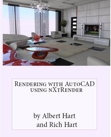
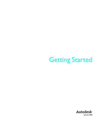
Draw to ScaleDrawing scale is something you consider when laying out your drawing. You establish scaledifferently in CAD than you do with manual drafting. 5 ; 6 ( 3 *) With AutoCAD andAutoCAD LT, you first decidewhat units of measurementyou will use, and then drawyour model at 1:1 scale. ; 5 ;5 ;Draw the object at 1:1 scale in the units youchoose.With manual drafting, youmust determine the scale of aview before you startdrawing. This scale comparesthe size of the actual object tothe size of the model drawnon paper.For example, when you draw a motor part, thelength of one unit might equal one millimeteror one inch. When you draw a map, one unitmight equal one kilometer or one mile.This drawing of a mechanical carriage usesmillimeters for the length of one unit. Views ofthe part were scaled later to create the layoutfor the printed drawing.5 5 5 5() 5 5 When you lay out and plot your drawing, youcan specify any scale.Draw to Scale 3
352326(' (/(9 7,21 6287 @ & % ;; 352326(' *5281' )/225 3/ 1 &
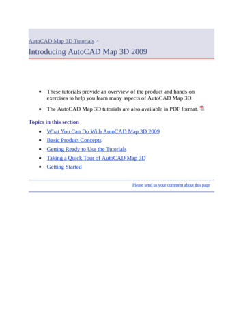
Lay Out Your DrawingOn paper, a layout is constrained by the sheet size you use. In CAD, you are not limited to oneparticular layout or sheet size.When you draft manually, youfirst select a sheet, which usuallyincludes a preprinted border andtitle block. Then you determinethe location for views—plans,elevations, sections, and details.Finally, you start to draw.You create your basic design, ormodel, in a drawing area called modelspace.With AutoCAD and AutoCAD LT,you first draw your design, ormodel, in a working environmentcalled model space. You can thencreate a layout for that model in an environmentcalled paper space.A layout represents a drawing sheet. It typicallycontains a border, title block, dimensions, generalnotes, and one or more views of the modeldisplayed in layout viewports. Layout viewports areareas, similar to picture frames or windows,through which you can see your model. You scalethe views in viewports by zooming in or out.In this drawing of a cottage, layout viewportsdisplay the model in plan and elevation views.When you’re ready to print, you can arrangedifferent views of your model in a layout.Lay Out Your Drawing 5
Organize Drawing InformationIn both manual drafting and CAD, you need a way to organize your drawing content—a method forseparating, sorting, and editing specific drawing data.With manual drafting, you can separateinformation onto individual transparentoverlays. For example, a building plan mightcontain separate overlays for its structural,electrical, and plumbing components.With AutoCAD and AutoCAD LT, layers areequivalent to transparent overlays. As withoverlays, you can display, edit, and print layersseparately or in combination.You can name layers to help track content, and lock layers sothey can't be altered. Assigning settings such as color, linetype, orlineweight to layers helps you comply with industry standards.Turn off layers to hide complexdetails as you work.You can also use layers to organize drawing objects for plotting.Assigning a plot style to a layer makes all the objects drawn onthat layer plot in a similar manner.This drawing of a press uses layers to define different linetypesand colors.Display layers when you needto see all components.Organize Drawing Information 7
Establish Drafting StandardsWhether you work as a member of a team or on an individual project, developing standards is arequirement for efficient communication.Manual drafting requires meticulousaccuracy in drawing linetypes,lineweights, text, dimensions, andmore. Standards must be establishedin the beginning and appliedconsistently.With AutoCAD and AutoCAD LT, youcan ensure conformity to industry orcompany standards by creating stylesthat you can apply consistently.You can create styles for text, dimensions, andlinetypes. A text style, for example, establishes font andformat characteristics such as height, width, and slant.You can save styles, layers, layouts, title block andborder information, and some command settings indrawing template files. Using drawing templates helpsyou quickly start new drawings that conform tostandards.This drawing of a roadway plan uses styles to maintaindrafting standards for text, dimensioning, andlinetypes.Dimension, text, and linetypestyles can be established in atemplate drawing and used forcreating new drawings.Establish Drafting Standards 9
Draw EfficientlyDraw with less effort and revise with more speed: these are two primary reasons you use CAD. Youare provided with a complete set of drawing and editing tools to help eliminate repetitive, timeconsuming drafting tasks.With manual drafting, you use drawingtools that include pencils, scales,compasses, parallel rules, templates, anderasers. Repetitive drawing and editingtasks must be done manually.You can save drafting time by drawing onehalf of an item and then mirroring it to createthe other half.In AutoCAD and AutoCAD LT, you canchoose from a variety of drawing toolsthat create lines, circles, spline curves,and more.You can easily move, copy, offset, rotate, and mirrorobjects. You can also copy objects between opendrawings.In this drawing of a trolley, copying and mirroring wereused to create repeated and symmetrical features.Offsetting was also used to draw parallel lines moreefficiently.Draw Efficiently 11
Draw AccuratelyEngineering and architectural drawings require a high degree of accuracy. With CAD, you draft moreaccurately than with manual methods.With objectsnaps, when youplace your cursorhere you can snap to thecenter pointautomatically.With manual drafting, you mustdraw objects carefully to ensurecorrect size and alignment. Objectsdrawn to scale must be manuallyverified and dimensioned.With AutoCAD and AutoCAD LT,you can use several methods toobtain exact dimensions.The simplest method is to locatepoints by snapping to an interval ona rectangular grid.Another method is to specify exact coordinates.Coordinates specify a drawing location by indicatinga point along an X and Y axis or a distance and anglefrom another point.With object snaps, you can snap to locations onexisting objects, such as an endpoint of an arc, themidpoint of a line, or the center point of a circle.With polar tracking, you can snap to previously setangles and specify distances along those angles.The polar tracking featuredisplays visual guidelines atspecific angles and can snapthe cursor to an angle.In this drawing of a pumping station, object snaps wereused to ensure that lines connected perfectly. Polartracking was used to draw lines at correct angles.Draw Accurately 13
View Your DrawingThe power of CAD makes it easy for you to quickly view different parts of your design at differentmagnifications.You can zoom out to see more of yourdesign, or zoom in to see more detail.With manual drafting, the sizeand resolution of your drawingis fixed.With AutoCAD and AutoCADLT, the size and resolution ofyour drawing can be changed asneeded.To do detailed work, you canincrease display size by zoomingin. You can zoom out to displaymore of the drawing. To move to another sectionof a drawing, you pan the drawing withoutchanging magnification.You can zoom and pan to create the best workingconditions. This can be invaluable when workingon large and detailed drawings, such as thishealth spa plan.You can pan to shift to another area of yourdesign.View Your Drawing 15
/
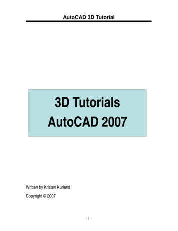
Create Dimensions and TextCreating accurate dimensions and consistent, legible text is a time-consuming task for the manualdrafter. CAD provides ways to streamline this task.With manual drafting, if youresize any part of the drawing,you must erase and thenredraw the dimensions.Changing text can ofteninvolve relettering the wholedrawing.If you make dimensions associative, you can update thedimension size and value automatically when youstretch or scale the dimensioned object.With AutoCAD and AutoCADLT, you create associativedimensions and text on thelayout in paper space.Associative dimensions aretied to the underlying model.Changes to the model automatically update thedimension values.Standard types of dimensions include linear,radial, ordinate, angular, baseline, and more.You can easily revise the content, font, size,spacing, and rotation of text in dimensions andnotes.You can create leader lines with associated text. If youmove the text, the leader is adjusted automatically.In this detail drawing of a gutter, the text,leaders, and dimensions describe the requiredhardware.Create Dimensions and Text 17
Modify Your DrawingRevisions are a part of any drawing project. Whether you work on paper or with CAD, you will needto modify your drawing in some way.On paper, you must erase and redraw to make revisions to your drawing manually.CAD eliminates tedious manual editing by providing a variety of editing tools. Ifyou need to copy all or part of an object, you don’t have to redraw it. If you needto remove an object, you can erase it with a few clicks of the mouse. And if youmake an error, you can quickly undo your actions.Once you draw an object, you never need to redraw it. You can modify existingobjects by mirroring, rotating, scaling, stretching, trimming, and more. You canalso change object properties, such as linetype, lineweight, color, and layer, at anytime.Once you draw something, you can easily copy it withouthaving to re-create it.These before-and-after drawings show some typical edits to a house elevation. The revision cloudfeature is used to mark areas of change.Modify Your Drawing 19
20
IntroductionWhy You Should Use this Guide . . . . . . . . . . . . . . . . . . . . . . . . . . . . . . . . . . . . . 22Tutorials and Command Access . . . . . . . . . . . . . . . . . . . . . . . . . . . . . . . . . . . . . . 22Get Additional Information. . . . . . . . . . . . . . . . . . . . . . . . . . . . . . . . . . . . . . . . . . 23
Why You Should Use this GuideThis Getting Started guide provides an introduction to the most commonly used features of bothAutoCAD and AutoCAD LT. Use it to learn the basic features so you can begin working quickly.Because you are provided with a rich set of features, there are often many ways of accomplishing atask. This guide focuses on the following: What do you need to know to get started? What is the recommended method for using the features presented?After you become more familiar with the features, you will find your own ways of working efficientlybased on the type of work that you do.Tutorials and Command AccessThere are severals ways you can access commands in AutoCAD and AutoCAD LT. They can beaccessed through the command line, the ribbon, toolbars, palettes, and the Menu Browser.Because the ribbon might have been customized, and some commands are not accessible from theribbon, the tutorials in this guide usually direct you to access commands through the Menu Browser.Menu Browser22 Chapter 1 Introduction
NOTE All screen shots and dialog boxes in this guide display AutoCAD LT in the title bar. For theexplanations and tutorials in the Getting Started guide, there is no difference whether you use AutoCADor AutoCAD LT. The features presented are identical.Get Additional InformationAdditional resources are available when you need more information. From the Help menu, you canaccess the following resources: Help provides procedures, conceptual information, and command descriptions. You can alsopress F1 at the Command prompt, in a dialog box, or at a prompt within a command to displayHelp information. New Features Workshop provides a series of overviews about new features. Additional Resources provides several options for additional help from the Web.Access Related Topics in the Help SystemKeyword references are displayed at the end of most Getting Started topics. For example, thefollowing information indicates that you can find concepts, procedures, commands, and systemvariables related to the LINE command by entering line in the Index tab of the Help window.LINETry it: Locate a Help topic using a keyword Start AutoCAD or AutoCAD LT and press the F1 key. Then follow the steps in the illustration.4 Click to display a conceptrelated to the selected topic5 Click to listprocedures related tothe selected topic6 Click to listcommands related tothe selected topic1 Click theIndex tab2 Enter akeyword3 Double-click toview a topicGet Additional Information 23
Tutorial: Use the Help SystemIn this tutorial, you will use the Help system to find information about how to start a drawing witha template file and how to create a layout.NOTE It is important to learn how to use the Help system effectively. The Help system can provideanswers to save you from needless frustration.1 Start AutoCAD or AutoCAD LT and press F1 to display the Help window.2 In the left pane of the Help window, click the Contents tab if necessary to display the table ofcontents. Then click the plus sign ( ) next to User’s Guide.The User’s Guide expands to display a list of chapters.3 In the left pane, click directly on the title, Start, Organize, and Save a Drawing. The right pane ofthe Help window displays links to several topics, with descriptions for each one.4 In the right pane, click Start a Drawing. Then click Use a Template File to Start a Drawing.You have navigated to a destination topic in the Help system. Notice that the table of contentsin the left pane displays the topic structure for easy navigation.24 Chapter 1 Introduction
5 Click the Procedure tab. Then click the first procedure on the list. Click the Procedure tab toredisplay the list.6 Click the Quick Reference tab. The Quick Reference tab lists all commands and system variablesthat are associated with this topic.If you click a link on this tab, the Command Reference is opened in Help, and provides detailsabout command and dialog box options.7 Next, in the left pane, click the Search tab.You will now locate topics that contain the word layout.8 Type the word layout and press ENTER.Several topics that contain the word layout are displayed. For the best results, enter severalkeywords or an exact phrase in quotes.NOTE You can click the column labeled Title to sort the list of topics alphabetically. Then, clickthe column labeled Location to sort the list of topics by book: Command Reference, User’s Guide,and so on.9 Scroll down to find the User’s Guide topic, Work on a Layout Tab. Then double-click the topic.The topic is displayed. But how do you know where you are in the table of contents? How canyou display an adjacent, related topic?Get Additional Information 25
10 In the left pane, click the Contents tab.The table of contents opens to the current topic. Use this method to find related topics easily.NOTE If the table of contents does not automatically open to the current topic, click the Concept tabin the right pane.11 In the left pane, right-click any topic and then click Close All.This is a quick method for collapsing the table of contents when too many subtopics aredisplayed.12 Close the Help window.26 Chapter 1 Introduction
For more information, read Use the Help System Efficiently. In the Help system, on the Contents tab,click User’s Guide Get Information Find the Information You Need Use the Help SystemEfficiently.To get startedActionMenu BrowserAccess the Help systemHelp HelpUse New Features WorkshopHelp New Features WorkshopFind training resourcesHelp Additional Resources Online Training ResourcesHelp systemHELPReview and Recall1 What is the purpose of the tabs in the right pane of the Help window?2 In the left pane of the Help window, when would you use the Contents tab rather than the Index tab?3 From what menu can you get information about new features?Get Additional Information 27
28
Work with CommandsUse the Mouse . . . . . . . . . . . . . . . . . . . . . . . . . . . . . . . . . . . . . . . . . . . . . . . . . . . 30Cancel a Command. . . . . . . . . . . . . . . . . . . . . . . . . . . . . . . . . . . . . . . . . . . . . . . . 30Start a Command . . . . . . . . . . . . . . . . . . . . . . . . . . . . . . . . . . . . . . . . . . . . . . . . . 30Undo or Redo Commands . . . . . . . . . . . . . . . . . . . . . . . . . . . . . . . . . . . . . . . . . . 34
Use the MouseMost people use a mouse as their pointing device. On a two-button mouse, the left button is usuallythe pick button, used to specify points or select objects in the drawing area. With the right button,you can display a shortcut menu that contains relevant commands and options. Different shortcutmenus are displayed depending on where you move the cursor.specify points or select objectsdisplay a shortcut menurotate to zoom, press to panNOTE To see what options are available in any situation, try right-clicking to display a shortcut menu.A wheel mouse is a two-button mouse with a small wheel between the buttons. This wheel can berotated or pressed down to zoom and pan your drawing quickly. It is highly recommended that youuse a wheel mouse.Cancel a CommandIf you accidentally click in the screen, display a shortcut menu, or start a command, you can alwaysescape by pressing the ESC key on your keyboard.Try it: Cancel a selection Click in the drawing area and move the mouse. You are now in an object selection mode. PressESC to cancel.Start a CommandYou can start a command using the Menu Browser, a toolbar, a palette, or the command line. BecauseAutoCAD and AutoCAD LT are very flexible, you can work in the way that feels most comfortableto you.You can choose commands from several different kinds of menus:30 Chapter 2 Work with Commands
Menu Browser access is from the bright red button at the top-left corner of the applicationwindow. All the commands for the tutorials in this book are accessible from these menus. The Object Snap menu is displayed when you hold down SHIFT and click the right mouse button.Object snaps facilitate precision drawing by snapping the cursor onto a feature on an object suchas the endpoint of a line or the center of a circle. Shortcut menus are displayed when you click the right mouse button. Different menus aredisplayed when you right-click an object, right-click in the drawing area, right-click a toolbar, orright-click within a dialog box, palette, or window.Start Commands on the Command LineYou can initiate commands by typing them on the command line within the command window insteadof using toolbars or menus. Additionally, some commands must be completed on the command line,regardless of how they are started.command windowcommand lineSome commands have abbreviated names or command aliases. For example, you can enter c as analias for CIRCLE.After you type the command on the command line, press ENTER or SPACEBAR to start thecommand. You can also repeat the previous command by pressing ENTER or SPACEBAR.NOTE In this guide and in the Help system, when you are instructed to enter something, type the boldface value on the command line, and then press the ENTER key.Specify a Command OptionWhen you start a command, you will often see a set of options on the command line. For example,when you enter the CIRCLE command, the following prompt is displayed on the command line:Specify center point for circle or [3P/2P/Ttr (tan tan radius)]:The default option, “Specify center point for circle,” is displayed before the square brackets. Alternateoptions are displayed between the aquare brackets. To accept the default option, enter coordinate values, or use the pointing device to click a centerpoint in the drawing area. To choose a different option, enter the capitalized letters in the option name. For example, type2P and press ENTER to choose the Two-Point option.Start a Command 31
Use the Dynamic PromptIn addition to the prompt on the command line, a similar prompt is displayed next to the cursorcalled the dynamic prompt.With the dynamic prompt, you can keep your eyes on your work and you don’t have to look downto the command line.To display command options in the dynamic input prompt, press the DOWN ARROW key, and thenclick an option on the menu.Try it: Use the Menu Browser to draw a line1 Click Menu Browser Click Draw Click Line.2 At the Specify First Point prompt, click anywhere in the drawing area to locate a point.The prompt changes: Specify Next Point or [Undo].3 At the Specify Next Point or [Undo] prompt, click anywhere else in the drawing area to specify theendpoint of the line segment.4 Create a second line segment by clicking again to locate another point.The Specify Next Point or [Undo] prompt is repeated so you can continue to draw segments untilyou end the LINE command.5 Press ENTER to end the LINE command.The two line segments that you just created share an endpoint, but are separate objects.6 Click Modify Erase, and click each line. Then press ENTER to end the erase command.Try it: Use the ribbon to draw a line1234Home tab Draw panel Click the Line button.32 Draw two line segments.Home tab Modify panel Click the Erase button.Click each line and then press ENTER to erase the lines.Chapter 2 Work with Commands
Try it: Use the command line to draw a line1 On the command line, type line or the letter L. Press ENTER.2 Click anywhere in the drawing area to locate a point.3 At the Specify Next Point or [Undo] prompt, click anywhere else in the drawing area to specifythe endpoint of the line segment.4 At the Specify Next Point or [Undo] prompt, click anywhere else in the drawing area to specifythe endpoint of the line segment.5 Type u and press ENTER to undo the last line segment and click another location for theendpoint.6 Then type c (Close) and press ENTER to add a third line segment that connects to the initial pointand ends the command.Try it: Use the command line to draw a circle1 On the command line, enter circle or the letter c (type c and press ENTER).2 At the Specify Center Point for Circle prompt, click anywhere in the drawing area to locate apoint.345678At the Specify Radius of Circle prompt, enter 5 (type 5 and press ENTER).On the command line, press ENTER to repeat the CIRCLE command.Enter 2P to create a circle using two points (type 2P and press ENTER).Click anywhere in the drawing to locate each point.Repeat the CIRCLE command several more times, using each of the other options.When you’re done, enter erase or e, and click each circle to select it. Then press ENTER to erasethe selected circles.Try it: Use the dynamic prompt to draw a circle1 At the dynamic prompt, enter circle or the letter c.2 At the Specify Center Point for Circle prompt, press the DOWN ARROW key.3 Click one of the CIRCLE options on the menu and complete the command.Start a Command 33
Undo or Redo CommandsOccasionally you will need to undo some of your work. Two Standard toolbar buttons reversemistakes in your drawings.UndoRedo Undo. You can backtrack previous actions. For example, click Undo to delete an object that youjust created. Redo. You can reinstate the actions that you backtracked with Undo. For example, click Redo torestore the object that you just undid.To get startedActionShortcut MenuKeyboardEnd a commandRight-click EnterENTER or SPACEBARRepeat a commandRight-click Repeat action ENTER or SPACEBARCancel a commandRight-click CancelESCUndo the previous commandRight-click Undo action U and press ENTERHelp systemOPTIONS, U, UNDO, REDOReview and Recall1 What are three ways that you can start a command?2 What other key can you use to end or repeat a command in addition to ENTER?3 What should you do to cancel a command?34 Chapter 2 Work with Commands
It will be easier to create or modify objects inthis drawing by zooming in to magnify theview.Once you have zoomed in, yo
With AutoCAD and AutoCAD LT, you first draw your design, or model, in a working environment called model space. You can then create a layout for that model in an environment called paper space. A layout represents a drawing sheet. It typically contains a border, title block, dime