Transcription
Course: Digital Communication (EC61)Course instructors:1. Mr. H. V.KumaraSwamy, RVCE, Bangalore2. Mr. P.Nagaraju, RVCE, Bangalore3. Ms. M.N.Suma, BMSCE, BangaloreTEXT BOOK:“Digital Communications”Author: Simon Haykin Pub: John Wiley Student Edition, 2003Reference Books:1. “Digital and Analog Communication Systems” –K. Sam Shanmugam, John Wiley, 1996.2. “An introduction to Analog and Digital Communication”Simon Haykin, John Wiley, 20033. “Digital Communication- Fundamentals & Applications” –Bernard Sklar, Pearson Education, 2002.4. “Analog & Digital Communications”HSU, Tata Mcgraw Hill, II edition
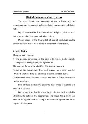
Chapter-1: IntroductionThe purpose of a Communication System is to transport an information bearing signalfrom a source to a user destination via a communication channel.MODEL OF A COMMUNICATION SYSTEMInformationSource andInputTransducerI/P SignalDestinationand OutputTransducerO/P SignalTRANSMITTERCHANNELRECEIVERFig. 1.1: Block diagram of Communication System.The three basic elements of every communication systems are Transmitter,Receiver and Channel.The Overall purpose of this system is to transfer information from one point(called Source) to another point, the user destination.The message produced by a source, normally, is not electrical. Hence an inputtransducer is used for converting the message to a time – varying electrical quantitycalled message signal. Similarly, at the destination point, another transducer converts theelectrical waveform to the appropriate message.The transmitter is located at one point in space, the receiver is located at someother point separate from the transmitter, and the channel is the medium that provides theelectrical connection between them.The purpose of the transmitter is to transform the message signal produced by thesource of information into a form suitable for transmission over the channel.The received signal is normally corrupted version of the transmitted signal, whichis due to channel imperfections, noise and interference from other sources.The receiver has the task of operating on the received signal so as to reconstruct arecognizable form of the original message signal and to deliver it to the user destination.Communication Systems are divided into 3 categories:1. Analog Communication Systems are designed to transmit analog informationusing analog modulation methods.2. Digital Communication Systems are designed for transmitting digital informationusing digital modulation schemes, and3. Hybrid Systems that use digital modulation schemes for transmitting sampled andquantized values of an analog message signal.
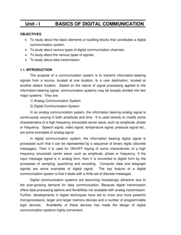
ELEMENTS OF DIGITAL COMMUNICATION SYSTEMS:The figure 1.2 shows the functional elements of a digital communication system.Source of Information:1. Analog Information Sources.2. Digital Information Sources.Analog Information Sources Microphone actuated by a speech, TV Camera scanning ascene, continuous amplitude signals.Digital Information Sources These are teletype or the numerical output of computerwhich consists of a sequence of discrete symbols or letters.An Analog information is transformed into a discrete information through theprocess of sampling and quantizing.Digital Communication SystemSource ave foBinary StreamChannelReceived SignalUser rFig 1.2: Block Diagram of a Digital Communication SystemSOURCE ENCODER / DECODER:The Source encoder ( or Source coder) converts the input i.e. symbol sequenceinto a binary sequence of 0’s and 1’s by assigning code words to the symbols in the inputsequence. For eg. :-If a source set is having hundred symbols, then the number of bitsused to represent each symbol will be 7 because 27 128 unique combinations areavailable. The important parameters of a source encoder are block size, code wordlengths, average data rate and the efficiency of the coder (i.e. actual output data ratecompared to the minimum achievable rate)
At the receiver, the source decoder converts the binary output of the channeldecoder into a symbol sequence. The decoder for a system using fixed – length codewords is quite simple, but the decoder for a system using variable – length code wordswill be very complex.Aim of the source coding is to remove the redundancy in the transmittinginformation, so that bandwidth required for transmission is minimized. Based on theprobability of the symbol code word is assigned. Higher the probability, shorter is thecodeword.Ex: Huffman coding.CHANNEL ENCODER / DECODER:Error control is accomplished by the channel coding operation that consists ofsystematically adding extra bits to the output of the source coder. These extra bits do notconvey any information but helps the receiver to detect and / or correct some of the errorsin the information bearing bits.There are two methods of channel coding:1. Block Coding: The encoder takes a block of ‘k’ information bits from the sourceencoder and adds ‘r’ error control bits, where ‘r’ is dependent on ‘k’ and errorcontrol capabilities desired.2. Convolution Coding: The information bearing message stream is encoded in acontinuous fashion by continuously interleaving information bits and error controlbits.The Channel decoder recovers the information bearing bits from the coded binary stream.Error detection and possible correction is also performed by the channel decoder.The important parameters of coder / decoder are: Method of coding, efficiency, errorcontrol capabilities and complexity of the circuit.MODULATOR:The Modulator converts the input bit stream into an electrical waveform suitablefor transmission over the communication channel. Modulator can be effectively used tominimize the effects of channel noise, to match the frequency spectrum of transmittedsignal with channel characteristics, to provide the capability to multiplex many signals.DEMODULATOR:The extraction of the message from the information bearing waveform producedby the modulation is accomplished by the demodulator. The output of the demodulator isbit stream. The important parameter is the method of demodulation.
CHANNEL:The Channel provides the electrical connection between the source anddestination. The different channels are: Pair of wires, Coaxial cable, Optical fibre, Radiochannel, Satellite channel or combination of any of these.The communication channels have only finite Bandwidth, non-ideal frequencyresponse, the signal often suffers amplitude and phase distortion as it travels over thechannel. Also, the signal power decreases due to the attenuation of the channel. Thesignal is corrupted by unwanted, unpredictable electrical signals referred to as noise.The important parameters of the channel are Signal to Noise power Ratio (SNR),usable bandwidth, amplitude and phase response and the statistical properties of noise.Modified Block Diagram:(With additional blocks)From Other rChanneldecoderDemuxDemodulatorTo other DestinationsFig 1.3 : Block diagram with additional blocksSome additional blocks as shown in the block diagram are used in most of digitalcommunication system: Encryptor: Encryptor prevents unauthorized users from understanding themessages and from injecting false messages into the system. MUX : Multiplexer is used for combining signals from different sources so thatthey share a portion of the communication system.
DeMUX: DeMultiplexer is used for separating the different signals so that theyreach their respective destinations. Decryptor: It does the reverse operation of that of the Encryptor.Synchronization: Synchronization involves the estimation of both time and frequencycoherent systems need to synchronize their frequency reference with carrier in bothfrequency and phase.Advantages of Digital Communication1. The effect of distortion, noise and interference is less in a digital communicationsystem. This is because the disturbance must be large enough to change the pulsefrom one state to the other.2. Regenerative repeaters can be used at fixed distance along the link, to identify andregenerate a pulse before it is degraded to an ambiguous state.3. Digital circuits are more reliable and cheaper compared to analog circuits.4. The Hardware implementation is more flexible than analog hardware because ofthe use of microprocessors, VLSI chips etc.5. Signal processing functions like encryption, compression can be employed tomaintain the secrecy of the information.6. Error detecting and Error correcting codes improve the system performance byreducing the probability of error.7. Combining digital signals using TDM is simpler than combining analog signalsusing FDM. The different types of signals such as data, telephone, TV can betreated as identical signals in transmission and switching in a digitalcommunication system.8. We can avoid signal jamming using spread spectrum technique.Disadvantages of Digital Communication:1. Large System Bandwidth:- Digital transmission requires a large systembandwidth to communicate the same information in a digital format as comparedto analog format.2. System Synchronization:- Digital detection requires system synchronizationwhereas the analog signals generally have no such requirement.
Channels for Digital CommunicationsThe modulation and coding used in a digital communication system depend on thecharacteristics of the channel. The two main characteristics of the channel areBANDWIDTH and POWER. In addition the other characteristics are whether thechannel is linear or nonlinear, and how free the channel is free from the externalinterference.Five channels are considered in the digital communication, namely: telephonechannels, coaxial cables, optical fibers, microwave radio, and satellite channels.Telephone channel: It is designed to provide voice grade communication. Also good fordata communication over long distances. The channel has a band-pass characteristicoccupying the frequency range 300Hz to 3400hz, a high SNR of about 30db, andapproximately linear response.For the transmission of voice signals the channel provides flat amplituderesponse. But for the transmission of data and image transmissions, since the phasedelay variations are important an equalizer is used to maintain the flat amplituderesponse and a linear phase response over the required frequency band. Transmissionrates upto16.8 kilobits per second have been achieved over the telephone lines.Coaxial Cable: The coaxial cable consists of a single wire conductor centered inside anouter conductor, which is insulated from each other by a dielectric. The main advantagesof the coaxial cable are wide bandwidth and low external interference. But closelyspaced repeaters are required. With repeaters spaced at 1km intervals the data rate of 274megabits per second have been achieved.Optical Fibers: An optical fiber consists of a very fine inner core made of silica glass,surrounded by a concentric layer called cladding that is also made of glass. The refractiveindex of the glass in the core is slightly higher than refractive index of the glass in thecladding. Hence if a ray of light is launched into an optical fiber at the right obliqueacceptance angle, it is continually refracted into the core by the cladding. That means thedifference between the refractive indices of the core and cladding helps guide thepropagation of the ray of light inside the core of the fiber from one end to the other.Compared to coaxial cables, optical fibers are smaller in size and they offer highertransmission bandwidths and longer repeater separations.Microwave radio: A microwave radio, operating on the line-of-sight link, consistsbasically of a transmitter and a receiver that are equipped with antennas. The antennasare placed on towers at sufficient height to have the transmitter and receiver in line-ofsight of each other. The operating frequencies range from 1 to 30 GHz.Under normal atmospheric conditions, a microwave radio channel is very reliableand provides path for high-speed digital transmission. But during meteorologicalvariations, a severe degradation occurs in the system performance.
Satellite Channel: A Satellite channel consists of a satellite in geostationary orbit, anuplink from ground station, and a down link to another ground station. Both link operateat microwave frequencies, with uplink the uplink frequency higher than the down linkfrequency. In general, Satellite can be viewed as repeater in the sky. It permitscommunication over long distances at higher bandwidths and relatively low cost.
CHAPTER-7Spread – Spectrum ModulationIntroduction:Initially developed for military applications during II world war, that was lesssensitive to intentional interference or jamming by third parties.Spread spectrum technology has blossomed into one of the fundamental building blocksin current and next-generation wireless systemsProblem of radio transmissionNarrow band can be wiped out due to interferenceTo disrupt the communication, the adversary needs to do two things,(a) to detect that a transmission is taking place and(b) to transmit a jamming signal which is designed to confuse the receiver.SolutionA spread spectrum system is therefore designed to make these tasks as difficult aspossible.Firstly, the transmitted signal should be difficult to detect by an adversary/jammer, i.e.,the signal should have a low probability of intercept (LPI).Secondly, the signal should be difficult to disturb with a jamming signal, i.e., thetransmitted signal should possess an anti-jamming (AJ) propertyRemedyspread the narrow band signal into a broad band to protect against interferenceIn a digital communication system the primary resources are Bandwidth andPower. The study of digital communication system deals with efficient utilization ofthese two resources, but there are situations where it is necessary to sacrifice theirefficient utilization in order to meet certain other design objectives.For example to provide a form of secure communication (i.e. the transmittedsignal is not easily detected or recognized by unwanted listeners) the bandwidth of thetransmitted signal is increased in excess of the minimum bandwidth necessary to transmitit. This requirement is catered by a technique known as “Spread SpectrumModulation”.
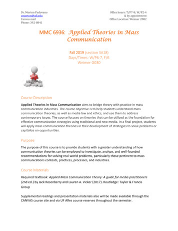
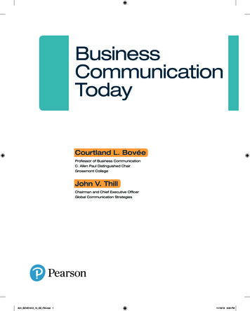
The primary advantage of a Spread – Spectrum communication system is itsability to reject ‘Interference’ whether it be the unintentional or the intentionalinterference.The definition of Spread – Spectrum modulation may be stated in two parts.1.Spread Spectrum is a mean of transmission in which the data sequence occupies aBW (Bandwidth) in excess of the minimum BW necessary to transmit it.2.The Spectrum Spreading is accomplished before transmission through the use ofa code that is independent of the data sequence. The Same code is used in thereceiver to despread the received signal so that the original data sequence may berecovered.s(t) wide bandb(t).r(t) wide bandb(t) Noise.NarrowBandc(t)Wide bandn(t)c(t)(noise)Wide band---- Transmitter-------- Channel--------- Receiver--------fig:1 spread spectrum technique.b(t) Data Sequence to be transmitted (Narrow Band)c(t) Wide Band codes(t) c(t) * b(t) – (wide Band)Fig: Spectrum of signal before & after spreadingWideBand
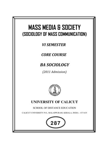
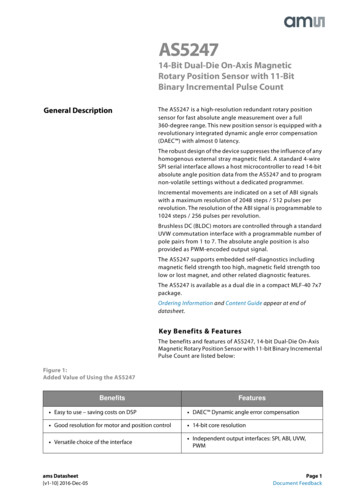
PSUEDO-NOISE SEQUENCE:Generation of PN ShiftRegister3SequenceOutputLogic CircuitFig 2: Maximum-length sequence generator for n 3A feedback shift register is said to be Linear when the feed back logic consists ofentirely mod-2-address ( Ex-or gates). In such a case, the zero state is not permitted. Theperiod of a PN sequence produced by a linear feedback shift register with ‘n’ flip flopscannot exceed 2n-1. When the period is exactly 2n-1, the PN sequence is called a‘maximum length sequence’ or ‘m-sequence’.Example1: Consider the linear feed back shift register as shown in fig 2involve three flip-flops. The input so is equal to the mod-2 sum of S1 and S3. If the initialstate of the shift register is 100. Then the succession of states will be as follows.100,110,011,011,101,010,001,100 . . . . . .The output sequence (output S3) is therefore. 00111010 . . . . .Which repeats itself with period 23–1 7 (n 3)Maximal length codes are commonly used PN codesIn binary shift register, the maximum length sequence isN 2m-1chips, where m is the number of stages of flip-flops in the shift register.
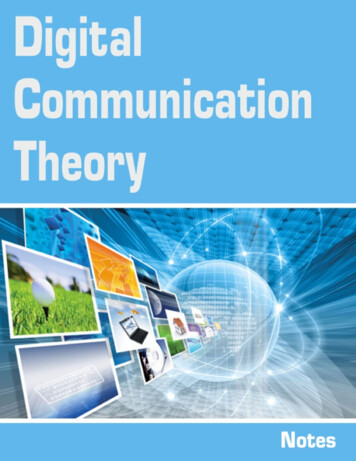
At each clock pulse Contents of register shifts one bit right. Contents of required stages are modulo 2 added and fed backto input.Fig: Initial stages of Shift registers 1000Let initial status of shift register be 000001001101011110 We can see for shift Register of length m 4.At each clock the change in state of flip-flop isshown. Feed back function is modulo two of X3andX4. After 15 clock pulses the sequence repeats.Output sequence is000100110101111
Properties of PN SequenceRandomness of PN sequence is tested by following properties1. Balance property2. Run length property3. Autocorrelation property1. Balance propertyIn each Period of the sequence , number of binary ones differ from binary zerosby at most one digit .Consider output of shift register 0 0 0 1 0 0 1 1 0 1 0 1 1 1 1Seven zeros and eight ones -meets balance condition.2. Run length propertyAmong the runs of ones and zeros in each period, it is desirable that about one half theruns of each type are of length 1, one- fourth are of length 2 and one-eighth are of length3 and so-on.Consider output of shift registerNumber of runs 80 0 0 1 0 0 1 1 0 1 0 1 1 1 1312211143. Auto correlation propertyAuto correlation function of a maximal length sequence is periodic and binary valued.Autocorrelation sequence of binary sequence in polar format is given byR c (k) 1 N c cN n 1 n n -kWhere N is length or period of the sequence andk is the lag of the autocorrelation 1 ifk l N R c (k) 1k lN NWhere l is any integer.we can also state Autocorrelation function asRc (k) 1N
{ No. of agreements – No. of disagreements in comparison of one full period }Consider output of shift register for l 11(7 8)151 15Rc (k) R c (k)Yields PN autocorrelation asRange of PN Sequence LengthsLength 0f Shift Register, mPN Sequence 119524287
Digital Communication Theory NoteseBookPublisher : VTU eLearningAuthor :Type the URL : http://www.kopykitab.com/product/1871Get this eBook
Communication Systems are divided into 3 categories: 1. Analog Communication Systems are designed to transmit analog information using analog modulation methods. 2. Digital Communication Systems are designed for transmitting digital information