Transcription
Hantle Inc.Hantle 1700Operator Manual
Table of ContentsTABLE OF CONTENTS1. INTRODUCTION1.1 Features1.1.1 About the Hantle 1700 1.2 SpecificationsHantle 1700 Specifications1.2.1 Dimensions and Component Locations1.2.2 LCD & Customer Keypad1.2.3 Cash Dispensing Unit1.2.4 Receipt Printer1.2.5 Main Control Board1.2.6 Operating Environment1.3 Warranty/Service2. INSTALLATION2.1 Hantle 1700 Installation2.1.1 Unpacking2.1.2 Physical Installation2.1.3 Hardware Setup3. PROGRAMMING3.1 Initial Setup3.1.1 Accessing the Operator Function Menu3.1.2 When An Error Occurs3.1.3 EPP Keypad3.2 The Host Setup Menu3.2.1 Key Management3.2.2 Set Host Telephone Number3.2.3 Set Terminal ID Number3.2.4 Health Check Message3.2.5 Connect Timer3.2.6 Remote Monitor3.2.7 Trial Day Total3.2.8 Host Processor Mode3.3 The System Setup Menu3.3.1 Set Clock3.3.2 ISO 1,2,3 En/Disable3.3.3 Optional Languages3.3.4 Change Passwords3.3.5 Modem Setup3.3.6 Modem Test3.3.7 RMS Ring Count3.3.8 Serial Number3.4 Customer Setup Menu3.4.1 Change Message3.4.2 BIN Lists3.4.3 Optional Function3.4.4 Surcharge Mode3.4.5 Advertisements1700 (Rev 1) Hantle 2010Operator Manual
Table of ContentsOperator Manual3.5 Transaction Setup3.5.1 Dispense Limit3.5.2 Denomination3.5.3 Fast Cash3.5.4 Low Currency Check4. OPERATION4.1 Opening and Closing4.1.1 Opening the Security Door4.1.2 Closing the Security Door4.1.3 Opening the top Bezel4.1.4 Closing the top Bezel4.1.5 Operating and Changing the Combination Lock4.1.6 Operating and Changing the Electronic Lock4.2 Cash Operations4.2.1 Adding Cash to the Cassette (TCDU)4.2.2 Emptying the Reject Bin (TCDU)4.2.3 Adding Cash to the Cassette (MCDU)4.2.4 Emptying the Reject Bin (MCDU)4.2.5 Loading the Receipt Printer4.3 Settlement Menu4.4 Journal Menu4.5 Reports Menu5. DIAGNOSTICS5.1 Diagnostics Menu6. CUSTOMER TRANSACTIONS6.1 Opening Procedure6.2 Withdrawal Transaction6.3 Balance Inquiry Transaction6.4 Transfer Transaction6.5 Closing Procedure6.6 Error RecoveryAPPENDIXA. Error CodesB. Pin Pad layout for Master Key / Download Mode / Clear NVRAMC. TDES Master Key installationD. CDU Preventative Maintenance1700 (Rev 1) Hantle 2010
IntroductionOperator ManualHantle 1700 1.1 FEATURES1.1.1 ABOUT THE Hantle 1700 Hantle introduces the next generation in retail ATMs. The Hantle 1700 raises thebar for quality, engineering and design. Built with the philosophies of durability,reliability and security you’ve come to expect from Hantle, the 1700 offers theabsolute best value in its class.While targeted for lower volume markets, the small footprint design retains all thestandard features of a higher end machine including: Triple DES and ADAcompliance, VISA / PCI or Interac certified encrypting PIN pad (EPP), a voiceguidance system, 56K modem and an integrated lighted topper sign.Weighing in at over 200lbs, the solidly constructed UL291 Listed – Business Hourvault provides security and offers the same modular construction for ease ofmaintenance.H/W FEATURESUL 291 Business Hour Service Vault featuring reinforced steel bottom & dial lock320 x 240 resolution, Trans-reflective QVGA display (Color LCD optional)56K modem800 note fixed cassette dispenser standard1700 note removable cassette dispenser optionalDIP type magnetic card reader (EMV Optional)2¼” Thermal receipt printerModular design for easy maintenanceLighted transaction guidance systemMeets ADA Standards for Height, Reach and Keypad layoutFUNCTIONAL FEATURESElectronic journal stores over 10,000 transactionsSupports English, Spanish and French languagesAvailability for 8 on screen advertisement graphicsDetailed average history report featureOn-screen error code descriptions for easy service1700 (Rev 1) Hantle 20101.1
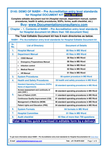
IntroductionOperator Manual1.2 SPECIFICATIONSHantle 1700 SPECIFICATIONS1.2.1 Dimensions and Component LocationFig. 1 DimensionsWEIGHT: 206 lbs.1700 (Rev 1) Hantle 20101.2
IntroductionOperator ManualComponent Location1. LCD & Customer Keypad2. Card Reader Slot3. Receipt Printer Slot4. Cash Tray5. Front Panel6. Front Panel Lock7. Security Cover8. Security Cover Lock9. Security Door10. Combination Lock1700 11. Security Door Handle12. Cash Dispensing Unit13. Receipt Printer14. Main Control Board15. Ear Phone Jack16. Power Supply17. Speaker.18. ADA Board19. Card Reader(Rev 1) Hantle 20101.3
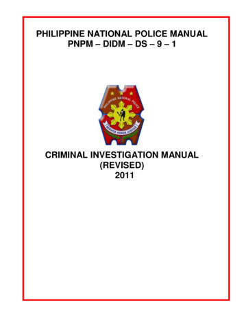
IntroductionOperator Manual1.2.2 LCD & Customer KeypadLightedTopperLCD PanelFunction KeysLighted TransactionGuidanceReceipt PrinterCard ReaderVoice GuidanceEPP KeypadFig. 3 LCD & Customer KeypadLCDScreen Size: 5.7”Mono Trans-reflective (Color LCD Optional)Resolution: 320 x 240 QVGADisplay Characters: 40 x 15 (Standard Characters)8 LCD Function KeysKEYPADCertified PCI/VISA or Interac EPP (Encrypting Pin Pad)10 Alphanumeric, 3,4, CANCEL, CLEAR, ENTER, BLANK KeypadsVoice Guidance PortVoice assisted operation available through the headphone jack on the front bezel1700 (Rev 1) Hantle 20101.4
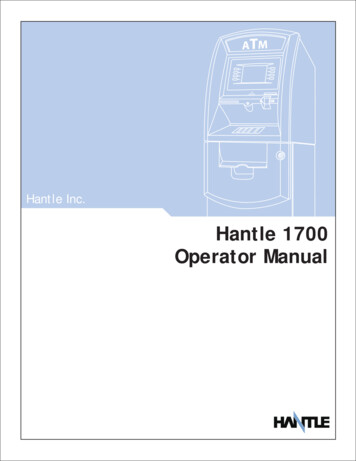
IntroductionOperator Manual1.2.3 Cash Dispensing UnitCash Dispensing Unit(Standard model - TCDU)CASH DISPENSING UNITDispensing Speed: 2.5 notes/secondCapacity of 800 new notes (fixed cassette)Lockable Reject BinDouble note detect module*Optional dispensers include:1700 note removable cassette(MCDU)1700 (Rev 1) Hantle 20101.5
IntroductionOperator Manual1.2.4 Receipt PrinterReceipt PrinterRECEIPT PRINTERThermal line printer36 characters/lineSemi-automatic roll paper settingMotorized front push rollersPAPER SPECIFICATIONSOne sided thermal paperFactory paper is thermal side out (but either way will work)6 inch outside diameter roll2 ¼” inch wideCore inside diameter 11/16 inch21# weight (paper thickness)1700 (Rev 1) Hantle 20101.6
IntroductionOperator Manual1.2.5 Main Control BoardARM based 32-bit CPUModem: 56,000 bps dial-up modem (standard)Electronic Journal: 10,000 transactionsBattery back-up for set-up parameters (NVRAM)Real time clock32MB RAM1.2.6 Operating EnvironmentPOWER REQUIREMENTS110/220 VAC 10%, 50/60 Hz, 145 WattsPOWER CONNECTIONSFor warranty purposes, the Hantle 1700 series ATM must be connected to adedicated power circuit. This circuit must consist of line, neutral, and ground leadsconnected directly to the power circuit breaker panel. This circuit should not beshared with any other equipment. Use of a surge protector or uninterruptible powersupply is recommended.PHONE LINE REQUIREMENTSThe Hantle 1700 series ATM should be connected to a dedicated phone line. Thisline must be a direct dial “tone” or “pulse” line that is equipped with a standardtelephone wall jack (RJ-11). This line cannot be shared with any other equipment atthe location. Use of shielded (CAT5) phone cable is recommended for bestperformance and to reduce the chance of interference.TEMPERATUREIn storageWhile operating: 32 F - 123 F (0 C 49 C): 40 F - 95 F (5 C 35 C)HUMIDITYIn storageWhile operating1700 : 10% RH 90%, non-condensed: 15% RH 85%, non-condensed(Rev 1) Hantle 20101.7
IntroductionOperator Manual1.3 WARRANTY/SERVICEMANUFACTURERS WARRANTYHantle USA, Inc. provides a limited one-year parts warranty and a limited 30 daylabor warranty for the 1700 series ATM. Hantle guarantees your 1700 modelATM to be free from defects in materials and workmanship.The one-year parts warranty and 30-day labor warranty periods will begin 15 daysfrom the shipping date.WHAT IS COVERED:· Cash Dispensing Unit (CDU) and Cash Cassette· Receipt printer (SHU)· LCD module· Magnetic Card Reader (MCR)· EPP Keypad· Power Supply· Mainboard (CE)· Lock and locking mechanism **LIMITED 90 DAY WARRANTY**Dial and Electronic locks will be covered by a limited 90-day warranty beginning15 days from shipping date. Should the lock fail under normal use, Hantle willreplace the lock only. Services required to open the vault and or replace the lockare at the expense of the ATM owner.WHAT IS NOT COVERED:· Power cable and modem cable· Key lock and key· Plastic Bezels· Software upgrade· Receipt printer jam· Note jam· Forgotten password or combination of lock· Any damages from misuse, improper installation, and vandalism· Any damages from “brown out” or low power, lightning, or any other ‘acts of God’Your distributor/dealer may offer an enhanced or extended warranty in addition tothe original manufacturers one-year warranty. Once the manufacturers warrantyhas expired, all claims for warranty service must be resolved directly between thedistributor/dealer and the ATM owner.OBTAINING SERVICE: If you have any problems or questions about your HantleATM, your dealer or distributor is your primary contact for assistance/service. Yourmanufacturers warranty is provided through your dealer or distributor.1700 (Rev 1) Hantle 20101.8
Section 2: InstallationOperator ManualSECTION 2: INSTALLATION2.1 Hantle 1700 INSTALLATION2.1.1 UNPACKINGStep 1Once the ATM is unpackaged, do not discard the packaging materials until you haveverified any shipping damage claim. Contact your distributor immediately if you seeany shipping damage.Step 2Verify the contents carefully with the packing list to be sure all items listed areincluded. Notify your distributor of any shortages.2.1.2 PHYSICAL INSTALLATIONTo install the Hantle 1700 ATM, review the following steps:Step 1Place the system on a flat surface. The system has a tendency to tip over if thesurface is over 10 degrees. Be careful when opening the top or bottom of themachine as it will be off balance.Step 2Use the holes in the bottom of the vault to mark and drill the appropriate sized holesfor the anchors you will be using. (Anchors are not included). Hantle does notrecommend a particular size or type of anchor as each installation is differenthowever maximum anchor diameter is ½Step 3Install the anchors into the ground according to the anchor bolts locate sheet (4places). See manufacturer’s instructions for anchor installation.Step 4Place the 1700 ATM on top of the anchors.Step 5Open the Security cover with the key provided. See page 4.1 for Opening andClosing instructions.1700 (Rev 1) Hantle 20102.1
Section 2: InstallationOperator ManualStep 6Using the supplied combination (see lock manual for default combination), open thesecurity Door. This combination should be changed as soon as possible. Refer topage 4.5 (dial) or 4.7 (electronic) for instructions on opening or changing the lock.Step 7After the anchor nuts are in place, according to the anchor holes on the bottom ofthe ATM, secure the anchor bolts snugly. Do not over tighten anchors as it maydistort the vault and cause problems with the door linkage.END2.1.3 HARDWARE SETUPStep 1Verify the power voltage (115/220V) to be used and set theappropriate voltage on the power supply. Default will be115V. The default setting should be 115VStep 2Verify that the telephone line to be used for the ATM is in proper working order.Hantle recommends the use of shielded (CAT5) phone line in locations with closeproximity to other appliances.Step 3Open the security door and remove any shipping materials and note any warning orinstallation instructions. See page 4.1 for assistance.Use this key (2 included) toopen the top and bottom bezelsCassette key(removable cassette)Cassette key(fixed cassette)1700 (Rev 1) Hantle 20102.2
Section 2: InstallationOperator ManualStep 4Remove the cash cassette from the box (removable cassette dispensers only). Fillthe cassette or cash drawer with the appropriate amount of notes, and carefullyplace it in the Cash Dispensing Unit. Place the appropriate denomination label on thefront of the cassette. See page 4.9 for instruction.Step 5Before closing the vault, thoroughly test the combination lock by locking andunlocking the lock several times. It is much easier to diagnose potential lockproblems before shutting the door.Step 6Open the top of the ATM. Place the receipt paper in the Receipt Printer. The paperprints only on one side (shiny side) always check the roll when you install paper.Place the roll so that the coated side (shiny side) will be facing up. See page 4.12 forpaper loading instruction.Step 7Connect the Power cable and the telephone cable to the appropriate outlets on thewall. Verify that the AC power outlet is grounded. If you are installing theilluminated topper, make sure to completely install the power cord into the A/C Outplug on the power supply. The socket takes an extra push to fully seat the plug.Step 8Turn the power on and verify that all systems are operational. If any part on thesystem or its programming is not operational, an error code will be displayed. If anerror code is displayed, corrective action will be listed below it. If the error cannotbe corrected, please contact your distributor. If no error code is displayed, enter theOperator Function Menu and view the Error Summary (see programming section).END1700 (Rev 1) Hantle 20102.3
Section 3: ProgrammingOperator ManualSECTION 3: PROGRAMMING3.1 INITIAL SETUP3.1.1 ACCESSING THE OPERATOR FUNCTIONStep 1To access the Operator Function menu, press the following keys in order Enter ,then Clear , then Cancel then 1, then 2, then 3.Note: The Operator Function menu can only be accessed when the machine is eitherin service (“swipe your card” screen) or out of service. If the machine is attemptingto connect the host or initializing, you will not be able to use the key commands toaccess the Operator Function Menu.If you have trouble accessing the Operator Menu, power off the ATM and then eitheropen the vault door or remove the paper from the printer and power back on. Thiswill force the ATM to the Operator Menu.Step 2Once you successfully completed the keycombination, you will be prompted to enter apassword. There are 3 options for passwords. Operator Password (allows access to basicmenu structure)Service Password (allows access to basicand diagnostic menus)Master Password (allows access to allmenus including setup parameters)Passwords are very important to maintainingsecurity for your ATM. Your dealer /distributor will provide you with default
For warranty purposes, the Hantle 1700 series ATM must be connected to a dedicated power circuit. This circuit must consist of line, neutral, and ground leads connected directly to the power circuit breaker panel. This circuit should not be shared with any other equipment. Use of a surge protector or uninterruptible power supply is recommended. PHONE LINE REQUIREMENTS The Hantle 1700 .