Transcription
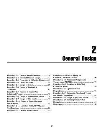
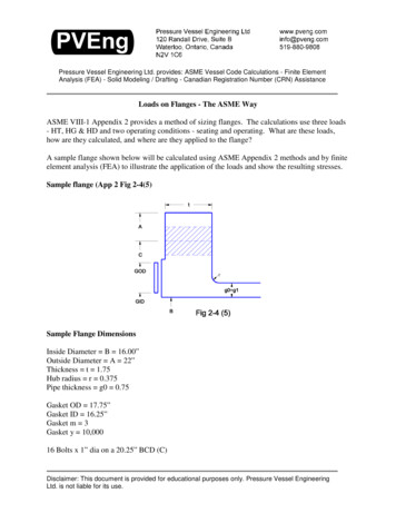
Pressure Vessel Engineering Ltd. provides: ASME Vessel Code Calculations - Finite ElementAnalysis (FEA) - Solid Modeling / Drafting - Canadian Registration Number (CRN) AssistanceLoads on Flanges - The ASME WayASME VIII-1 Appendix 2 provides a method of sizing flanges. The calculations use three loads- HT, HG & HD and two operating conditions - seating and operating. What are these loads,how are they calculated, and where are they applied to the flange?A sample flange shown below will be calculated using ASME Appendix 2 methods and by finiteelement analysis (FEA) to illustrate the application of the loads and show the resulting stresses.Sample flange (App 2 Fig 2-4(5)rSample Flange DimensionsInside Diameter B 16.00”Outside Diameter A 22”Thickness t 1.75Hub radius r 0.375Pipe thickness g0 0.75Gasket OD 17.75”Gasket ID 16.25”Gasket m 3Gasket y 10,00016 Bolts x 1” dia on a 20.25” BCD (C)Disclaimer: This document is provided for educational purposes only. Pressure Vessel EngineeringLtd. is not liable for its use.
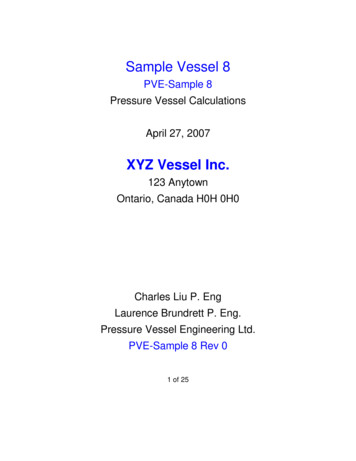
Sample flange - the FEA modelFlange Model16 holes on 20.25” BCD, 1” bolt size - only 1/2 of one bolt will be used for the FEA model dueto symmetry.Loads on Flanges.doc - Page 2 of 16
GasketHalf of the 1” bolt is added. A mirrored body creates a flanged pair.GasketLoadssLocFor FEA the bolt length is cut on the center of the gasket. The gasket is removed and is replacedby the loads it generates. Split lines can be seen where the gasket loads HT and HG are applied.Loads on Flanges.doc - Page 3 of 16
Load HD - OperatingHD is created by the pressure on the pipe attached to the flange. Force Pressure x Area.HD P * B 2 / 4The load is generated on center line of the pipe, but the ASME rules change the moment armdepending on the attachment method. When FEA is performed, the load should be applied to theattached pipe - the FEA program will determine how the load is distributed.Loads on Flanges.doc - Page 4 of 16
Load HT - OperatingHT is created by the internal pressure acting on the gasket:1)Pressure is applied to the exposed edge of the gasket2)The gasket tries to expand but is held in place by the flange faces3)The flange faces push backThe force between the gasket and the flange is shown as a triangle. The force is zero at the ODof the gasket (there is no pressure at the gasket OD and thus no leakage). At the inside edge, thepressure is the pressure in the pipe. HT is the average pressure along the length. mhT ismeasured at the point 1/3 up the triangle, the centroid of the force.The ASME rules reduce the width of the gasket. This load is a design rule, not a predictor ofactual flange stresses. For FEA analysis, the load HT is applied at the moment arm mhT awayfrom the bolt centerline.Loads on Flanges.doc - Page 5 of 16
Load HG - OperatingHG operating is the force required to keep the flange sealed against the operating pressure. It isgenerated by tightening the bolts. Load effective area x gasket factor m x Pressure. If theflange is self energizing (does not need additional force to seal such as an o-ring) then HGoperating 0Load HG operates through the center of the gasket, but the gasket size is reduced by the ASMErules to create an effective area. Correlation to real gasket properties is difficult - this load andits moment arm is a design rule, not a predictor of actual flange stresses.Loads on Flanges.doc - Page 6 of 16
Load HG - SeatingHG seating is the force required to seat the gasket into the flange gasket face and be leak tightagainst a pressure of 0 psi. (HG operating provides the load required to keep the seal as theoperating pressure is increased).The force HG is loosely based on gasket physical properties, but the gasket area used is modified(reduce) from the actual gasket width because the code y factors are too high. Correlation to realgasket properties is impossible - this load and its moment arm are a design rule, not a predictorof actual flange stresses.Force HG has an additional load added to it - the “gasket destroying” or “gasket crushing” force.The computed seating load on the gasket is increased to the average of the required bolt strengthand the available bolt strength. This code disaster greatly increases the required thickness offlanges far beyond the loads that the gasket can handle.As a designer, when the seating loads are too large and are caused by extra bolt area,several options are available:1) make the bolts smaller in diameter or fewer in number. Reducing the effective area of thebolts reduces this theoretical gasket crushing force.2) use weaker bolts - same idea as above.3) if material waste and cost are no object, make the flange thicker. This route often is usedwhen a custom appendix 2 flange must mate up to standard flanges such as B16.5 series whichseldom calculate to appendix 2 rules.Loads on Flanges.doc - Page 7 of 16
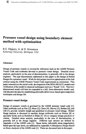
ASME Loads Applied to the FEA ModelHDHG operating HG seatingHTThe flange model with the HD, HG and HT loads applied.Combined operating and seating stresses case stresses. Higher stresses can be seen at the pipe toflange discontinuity. Bending stresses can also be seen in the bolt. Although the stresses lookhigh compared with the 20,000 psi membrane allowable stress for the flange and pipe, thestresses are minor if compared with a local discontinuity limit of 3x20,000 psi. This flangedesign although loaded to the maximum ASME allows can be considered to be lightly loadedand wasteful of materials.Loads on Flanges.doc - Page 8 of 16
Operating loads only - used for cycle life calculations (seating HG is removed). The gasket getsseated once, this is the load that the flange sees with each application and removal of pressure.The flange loads are extremely light for this flange that was designed around the gasket seatingcase.Loads on Flanges.doc - Page 9 of 16
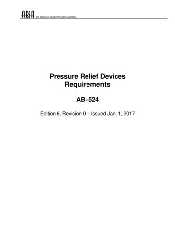
The Effective Seating Width of the GasketThe effective seating width of the gasket removes the correlation between the physicalproperties of the gasket material, and the calculated gasket loads. The seating width is typically1/2 * the square root of the actual gasket width (see table 2-5.2 for actual formulas which varydepending on the gasket seating arrangement and the gasket width). Traditionally, this was doneto allow for rotation of the flanges under load which reduced the actual width of the gasket incontact with the flange faces (it was presumed that the inside edge of the gasket was not incontact). In reality, the ASME rules, including the flange rotation limits in 2-14, do not allowenough flange rotation for the gasket to be partially in contact. This effective width calculationremoves any possible correlation between ASME flange calculation methods and flangemanufacturers provided m and y values. It was probably introduced because the table 2-5.1gasket factors are too high.The seating and operating loads are design rules and should not be expected to predictactual flange stresses. They can be used in FEA analysis to simulate loads in a manner similar toApp 2 methods as required by U-2(g).Widthb0 Width/20.5*sqrt(b0)Effective tive width for a common gasket arrangement - Table 2-5.2 sketches (1a) and (1b)Loads on Flanges.doc - Page 10 of 16
Effective Gasket Width1.200b0 Width/21.0000.5*sqrt(b0)Effective WidthEffective 0.8001.0001.2001.4001.6001.8002.000Actual WidthAttachmentsAttached are calculation sheets for:- ASME code calculation for this flange. This flange is limited by the seating case - inthis case seating of a high strength spiral wound gasket - m 3, y 10,000.- FEA loads for the operating and seating case- FEA loads for the operating only caseLoads on Flanges.doc - Page 11 of 16
1Flanges ver 4.262ASME VIII Div I Appendix 2Code Flange Calculations 536373839404142434445464748495051Page 1 of 3fd? - Select a flange designA [in] - flange ODBn [in] - ID, uncorrodedt [in] - flange thicknessrf [in] - hub corner radiusg0f [in] - hub thicknessg1 [in] - hub base thicknessrGOD [in] - gasket ODGID [in] - gasket IDm - gasket factorgy - gasket factor yBolting:20.250 varC [in] - bolt circle dia1.000 BoltOD [in] - bolt size16.0 Nbolt - number of boltsOperating Conditions:0.000 Corr [in] - corrosion allowance100.0 P [psi] - internal operating pressure0.0 Pe [psi] - external operating pressureMaterial Properties:NonCast CastMaterial? - Cast Or NonCast20,000 Sf [psi] - allowable flange stress at DESIGN temp.20,000 Sfa [psi] - Allowable Flange Stress at ASSEMBLY temp.27,900,000 Efo [psi] -Operating Flange Modulus27,900,000 Efs [psi] - Seating Flange Modulus20,000 Sb [psi] - allowable bolt stress at DESIGN temp20,000 Sba [psi] - allowable bolt stress at ASSEMBLY tempGeometry Constraints:rMin max(1/4*g1,0.188)MAX(1/4*0.75,0.188) 0.188NutG [in] )Rh [in] PVELookup("TEMATableD5","Lookup","Rh",BoltOD)E [in] Clearance varC/2-B/2-g0-Rh TEMA Table D-520.25/2-16/2-0.75-1.375 CkWrenchClr WrenchClearance 00 0 NutClearance varC/2-B/2-g0-rf-NutG/2 TEMA Table D-520.25/2-16/2-0.75-0.375-1.796/2 CkNutClr NutClearance 00.102 0 EdgeClearance (A-E)-varC TEMA Table D-5(22-1.063)-20.25 ckEdge EdgeClearance 00.687 0 Calculated Dimensions:g0 g0f-CorrgOne g1-CorrB Bn 2*CorrvarR (varC-B)/2 - gOne Gasket width in contactvarN (GOD-GID)/2 Gasket width in contactb0 varN / 2 Gasket seating width0.75-0 0.75-0 16 2*0 (20.25-16)/2 - 0.75 (17.75-16.25)/2 0.75 / 2 Acceptable0.7500.75016.0001.3750.7500.375
Flanges ver 3Page 2 of 3varb IF(b0 0.25,Sqrt(b0)/2,b0) Effective seating widthIF(0.375 0.25,SQRT(0.375)/2,0.375) 0.306varG IF(b0 0.25,GOD-2*varb,(GOD-GID)/2 GID)IF(0.375 0.25,17.75-2*0.306,(17.75-16.25)/2 16.25) 17.138hub rf Length of Hub0.375 0.375Bolt Loads: (VIII App 2-5)Bolt size and class:1-8 UNC 2A0.785*varG 2*P end load0.785*17.138 2*100 0.785*varG 2*Pe end load external pressure0.785*17.138 2*0 2*varb*3.14*varG*m*P contact load2*0.306*3.14*17.138*3*100 pi()/4 * B 2 * P end loadPI()/4 * 16 2 * 100 pi()/4 * B 2 * Pe end load external pressurePI()/4 * 16 2 * 0 H - HD face load23055 - 20106 He - HDe face load external0-0 H HP bolt load23055 9886 pi()*varb*varG*gy seating loadPI()*0.306*17.138*10000 Max(Wm1/Sb, Wm2/Sba) Bolt area requiredMAX(32941/20000, 164849/20000) RootArea [sq. in] PVELookup("BoltSizing","Lookup","Root Area",BoltOD)Ab RootArea*Nbolt0.566*16 CheckExcess Ab Am9.056 8.242 H He HP HD HDe HT HTe Wm1 Wm2 Am Flange Loads: (App 2-5)W [lb] (Am Ab)*Sba/2 seating conditionsHG [lb] Wm1 - H operating conditionsTBoltLoad [lb] (W Wm1)/NboltFlange Moment Arms: (Table App 2-6 - Integral flanges)mhD [in] varR 0.5*gOnemhT [in] (varR gOne mhG)/2mhG [in] 98.2420.5669.056Acceptable(8.242 9.056)*20000/2 172,98432941 - 23055 9,886(172984 32941)/16 12,8701.375 0.5*0.75 1.750(1.375 0.75 1.556)/2 1.841(20.25-17.138)/2 1.556Flange Moments: (App 2-6)MD [in-lb] HD * mhD end pressure20106 * 1.75 MT [in-lb] HT * mhT face pressure2949 * 1.841 MG [in-lb] HG * mhG gasket load9886 * 1.556 Mo1e [in-lb] HDe*(mhD-mhG) HTe*(mhT-mhG) total operating external0*(1.75-1.556) 0*(1.841-1.556) Mo1 [in-lb] Max(MD MT MG,Mo1e) total operatingMAX(35186 5428 15384,0) Mo2 [in-lb] W*(varC-varG)/2 total seating172984*(20.25-17.138)/2 Graphs: App 2-7.1-6 Values of F, f, T, U, V, Y and Zh0 sqrt(B*g0)SQRT(16*0.75) hh0 hub/h00.375/3.464 g1g0 gOne/g00.75/0.75 F PVELookup("F","FlangeFactor",hh0,g1g0)V PVELookup("V","FlangeFactor",hh0,g1g0)smallF 11 K A/B22/16 T PVELookup("T","FlangeFactorK",K)U PVELookup("U","FlangeFactorK",K)Y PVELookup("Y","FlangeFactorK",K)Z PVELookup("Z","FlangeFactorK",K)d (U/V)*h0*g0 2(6.877/0.55)*3.464*0.75 2 e F / h00.909 / 3.464 L (t*e 1)/T t 3/d(1.75*0.262 1)/1.765 1.75 3/24.36 47
Flanges ver 829Page 3 of 3Flange Seating Stress: (App 2-7,8)SHs smallF*ABS(Mo2) / ( L*gOne 2 * B)1*ABS(269196) / ( 1.047*0.75 2 * 16) CheckSHs SHs 1.5*(Sfa)28577 1.5*(20000) SRs (1.33*t*e 1)*ABS(Mo2) / (L*t 2*B)(1.33*1.75*0.262 1)*ABS(269196) / (1.047*1.75 2*16) CheckSRs SRs Sfa8454 20000 STs (Y*ABS(Mo2) / (t 2*B)) - Z*SRs(6.258*ABS(269196) / (1.75 2*16)) - 3.246*8454 SAs (SHs Max(SRs, STs))/2(28577 MAX(8454, 6943))/2 CheckSTs ABS(STs) SfaABS(6943) 20000 CheckSAs SAs Sfa18515 20000 Flange Operating Stress: (App 2-7,8)SHo smallF*Mo1/(L*gOne 2*B)1*55998/(1.047*0.75 2*16) CheckSHo SHo 1.5*(Sf)5945 1.5*(20000) SRo (1.33*t*e 1)*Mo1/(L*t 2*B)(1.33*1.75*0.262 1)*55998/(1.047*1.75 2*16) CheckSRo SRo Sf1759 20000 STo Y*Mo1/(t 2*B)-Z*SRo6.258*55998/(1.75 2*16)-3.246*1759 CheckSTo STo Sf1444 20000 SAo (SHo Max(SRo,STo))/2(5945 MAX(1759,1444))/2 CheckSAo SAo Sf3852 20000 Flange Flexibility: (App 2-14)Jseating (52.14*Mo2*V) / (L*Efs*g0 2*h0*0.3)(52.14*269196*0.55) / (1.047*27900000*0.75 2*3.464*0.3) CheckJSt ABS(Jseating) 1ABS(0.452) 1 Joperating (52.14*Mo1*V) / (L*Efo*g0 2*h0*0.3)(52.14*55998*0.55) / (1.047*27900000*0.75 2*3.464*0.3) CheckJOp ABS(Joperating) 1ABS(0.094) 1 le
18Flange Loads for FEA ver 1.12Page 1 of 2ASME VIII div 1 App 58359360361362363Combined Loads (Operating Seating Conditions) - DescriptionDimensions and Conditions:10.020 - B - ID, uncorroded0.990 - g1 - hub thickness0.000 - Corr - corrosion allowance13.0 - P, internal operating pressure13.37510.7500.500 - GOD - gasket OD - GID - gasket ID - m - gasket factor - gy - gasket factor y14.250 - varC - bolt circle dia0.875 - BoltOD, bolt size12.0 - Nbolt, number of boltsMaterial Properties: - Bolting Material25,000 - Sb - allowable bolt stress at DESIGN temp25,000 - Sba - allowable bolt stress at ASSEMBLY tempCalculated Dimensions:g0 g0-corr 0-0gOne g1 - corr 0.99-0B B 2*corr 10.02 2*0Corroded IDvarR (varC-B)/2 - gOne (14.25-10.02)/2 - 0.99varN (GOD-GID)/2 (13.375-10.75)/2Gasket Width in Contactb0 varN / 2 1.313 / 2gasket seating widthvarb min(Sqrt(b0)/2,b0) min(Sqrt(0.656)/2,0.656)eff seating widthvarG max(GOD-2*varb,(GOD-GID)/2 GID)gasket load reaction diameter max(13.375-2*0.405,(13.375-10.75)/2 10.75)Flange Loads (VIII App 2-5):H 0.785*varG 2*PHP 2*varb*3.14*varG*m*PHD pi/4 * B 2 * PHT H - HDWm1 H HPWm2 pi*varb*varG*gyAm max(Wm1/Sb, Wm2/Sba)Ab Root*NboltTotal Bolt Loads - lbs - (app 2-5):W (Am Ab)*Sba/2HG Wm1 - H 0.785*12.565 2*13 2*0.405*3.14*12.565*0.5*13end loadcontact load pi/4 * 10.02 2 * 13 1611 - 1025 1611 208 pi*0.405*12.565*0seating load max(1819/25000, 0/25000)req bolt area 0.431*12end loadface loadbolt load7/8-9 UNC 2A (0.073 5.172)*25000/2 1819 - 1611Flange Moment Arms - inch - (Table App 2-6 - Integral flanges):mhD varR 0.5*gOne 1.125 0.5*0.99mhT (varR gOne mhG)/2 (1.125 0.99 0.843)/2mhG (varC-varG)/2 (14.25-12.565)/2seating conditionsoperating conditionsend pressureface pressuregasket loadg0 gOne B varR varN b0 varb varG 0.0000.99010.0201.1251.3130.6560.40512.565H HP HD HT Wm1 Wm2 Am Ab 1,6112081,0255861,81900.0735.172W 65,559HG 208mhD 1.620mhT 1.479mhG 0.843Summary of Loads and Locations - Combined Operating and Seating - (lbs, inch) for ONE HALF boltOperating Seating ConditionsLoad (lbs)Acting Rad Loads for a model using ONE HALF bolt onlyHT/(Nbolt*2)24 5.646Gasket face pressure (Operating)(HG W)/(Nbolt*2)2,740 6.282Gasket load (Seating Operating)HD/(Nbolt*2)43 5.505End pressure (Operating)(Wm1 W)/(Nbolt*2)-2,807 7.125Bolt reaction balancing load (Seating Operating)Do not apply Wm1 W - use boundary conditions on the bolt to apply this balancing loadThis model has a sweep of 360º/(Nbolt*2) 15º for one half boltOmit end pressure HD if a closed pipe end is modelled and pressurized
18Flange Loads for FEA ver 1.12Page 1 of 2ASME VIII div 1 App 219Operating Load Only - 4355356357358359360361362363Dimensions and Conditions:16.000 - B - ID, uncorroded0.750 - g1 - hub thickness0.000 - Corr - corrosion allowance100.0 - P, internal operating pressure17.75016.2503.0010,000 - GOD - gasket OD - GID - gasket ID - m - gasket factor - gy - gasket factor yr20.250 - varC - bolt circle dia1.000 - BoltOD, bolt size16.0 - Nbolt, number of boltsMaterial Properties: - Bolting Material20,000 - Sb - allowable bolt stress at DESIGN temp20,000 - Sba - allowable bolt stress at ASSEMBLY tempCalculated Dimensions:g0 g0-corr 0-0gOne g1 - corr 0.75-0B B 2*corr 16 2*0Corroded IDvarR (varC-B)/2 - gOne (20.25-16)/2 - 0.75varN (GOD-GID)/2 (17.75-16.25)/2Gasket Width in Contactb0 varN / 2 0.75 / 2gasket seating widthvarb min(Sqrt(b0)/2,b0) min(Sqrt(0.375)/2,0.375)eff seating widthvarG max(GOD-2*varb,(GOD-GID)/2 GID)gasket load reaction diameter max(17.75-2*0.306,(17.75-16.25)/2 16.25)hub r 0length of hubFlange Loads (VIII App 2-5):H 0.785*varG 2*PHP 2*varb*3.14*varG*m*PHD pi/4 * B 2 * PHT H - HDWm1 H HPWm2 pi*varb*varG*gyAm max(Wm1/Sb, Wm2/Sba)Ab Root*NboltTotal Bolt Loads - lbs - (app 2-5):W (Am Ab)*Sba/2HG Wm1 - H 0.785*17.138 2*100 2*0.306*3.14*17.138*3*100end loadcontact load pi/4 * 16 2 * 100 23055 - 20106 23055 9886 pi*0.306*17.138*10000seating load max(32941/20000, 164849/20000)req bolt area 0.566*16end loadface loadbolt load1-8 UNC 2A (8.242 9.056)*20000/2 32941 - 23055Flange Moment Arms - inch - (Table App 2-6 - Integral flanges):mhD varR 0.5*gOne 1.375 0.5*0.75mhT (varR gOne mhG)/2 (1.375 0.75 1.556)/2mhG (varC-varG)/2 (20.25-17.138)/2seating conditionsoperating conditionsend pressureface pressuregasket loadg0 gOne B varR varN b0 varb varG 0.0000.75016.0001.3750.7500.3750.30617.138hub 0.000H HP HD HT Wm1 Wm2 Am Ab 23,0559,88620,1062,94932,941164,8498.2429.056W HG 9,886mhD 1.750mhT 1.841mhG 1.556Summary of Loads and Locations - Combined Operating and Seating - (lbs, inch) for ONE HALF boltOperating Seating ConditionsLoad (lbs)Acting Rad Loads for a model using ONE HALF bolt onlyHT/(Nbolt*2)92 8.284Gasket face pressure (Operating)(HG W)/(Nbolt*2)309 8.569Gasket load (Operating)W removed, HG remainsHD/(Nbolt*2)628 8.375End pressure (Operating)(Wm1 W)/(Nbolt*2)-1,029 10.125Bolt reaction balancing load (Operating)W removed, Wm1 remainsDo not apply Wm1 W - use boundary conditions on the bolt to apply this balancing loadThis model has a sweep of 360º/(Nbolt*2) 11.25º for one half boltOmit end pressure HD if a closed pipe end is modelled and pressurized
contact). In reality, the ASME rules, including the flange rotation limits in 2-14, do not allow enough flange rotation for the gasket to be partially in contact. This effective width calculation removes any possible correlation between ASME flange calculation methods and flang