Transcription
RULE REQUIREMENTS FORMATERIALS AND WELDING2002PART 2American Bureau of ShippingIncorporated by Act of Legislature ofthe State of New York 1862Copyright 2001American Bureau of ShippingABS Plaza16855 Northchase DriveHouston, TX 77060 USA
Rule Change Notice (2002)The effective date of each technical change since 1993 is shown in parenthesis at the end of thesubsection/paragraph titles within the text of each Part. Unless a particular date and month are shown,the years in parentheses refer to the following effective dates:(2000) and after(1999)(1998)(1997)1 January 2000 (and subsequent years)12 May 199913 May 199819 May 1997(1996)(1995)(1994)(1993)9 May 199615 May 19959 May 199411 May 1993Listing by Effective Dates of Changes from the 2001 RulesEFFECTIVE DATE 1 January 2001(based on the contract date for construction)Part/Para. No.Title/Subject2-1-1/15.1Permissible Variations inDimensions – ScopeStatus/RemarksTo clarify that mill scale is to be considered when theplate is produced for compliance with the specifiedunder toleranceSection 2-4-4To align ABS requirements with IACS UR P2 regardingfabrication of piping and non-destructive examinations,and to outline the requirements for the heat treatment ofpiping. This Section is applicable only to piping forinstallation on vessels to be built in accordance with theRules for Building and Classing Steel Vessels.iiPipingABS RULE REQUIREMENTS FOR MATERIALS AND WELDING . 2002
PART2ForewordFor the 1996 edition, the “Rules for Building and Classing Steel Vessels – Part 2: Materials andWelding” was re-titled “Rule Requirements for Materials and Welding – Part 2.” The purpose of thisgeneric title was to emphasize the common applicability of the material and welding requirements in“Part 2” to ABS-classed vessels, other marine structures and their associated machinery, and therebymake “Part 2” more readily a common “Part” of the various ABS Rules and Guides, as appropriate.Accordingly, the subject booklet, Rule Requirements for Materials and Welding – Part 2, is to beconsidered, for example, as being applicable and comprising a “Part” of the following ABS Rules andGuides:-Rules for Building and Classing Steel Vessels.-Rules for Building and Classing Steel Vessels Under 90 Meters (295 Feet) in Length-Rules for Building and Classing Mobile Offshore Drilling Units-Guide for Building and Classing High Speed CraftFor the 2002 edition, a new Section 4, “Piping” has been added to Part 2, Chapter 4, “Welding andFabrication”. This new Section is applicable only to piping for installation on vessels to be built inaccordance with the Rules for Building and Classing Steel Vessels.ABS RULE REQUIREMENTS FOR MATERIALS AND WELDING . 2002iii
PART2Rule Requirements for Materials and WeldingCONTENTSCHAPTER 1 Materials for Hull Construction . 1Section 1General Requirements. 3Section 2Ordinary-strength Hull Structural Steel. 15Section 3Higher-strength Hull Structural Steel . 29Section 4Low Temperature Materials . 39Section 5Hull Steel Castings . 41Section 6Hull Steel Forgings . 45CHAPTER 2 Materials for Equipment . 49Section 1Anchors. 51Section 2Anchor Chain . 59Section 3Rolled Steel Bars for Chain . 77CHAPTER 3 Materials for Machinery, Boilers, PressureVessels, and Piping . 81Section 1General Requirements. 87Section 2Steel Plates for Machinery, Boilers andPressure Vessels. 95Section 3Seamless Forged-steel Drums . 109Section 4Seamless-steel Pressure Vessels . 111Section 5Boiler and Superheater Tubes. 113Section 6Boiler Rivet and Staybolt Steel and Rivets . 129Section 7Steel Machinery Forgings . 131Section 8Hot-rolled Steel Bars for Machinery. 157Section 9Steel Castings for Machinery, Boilers andPressure Vessels. 159Section 10 Ductile (Nodular) Iron Castings . 163Section 11 Gray-iron Castings. 167Section 12 Steel Piping. 169Section 13 Piping, Valves and Fittings forLow-Temperature Service[Below -18 C (0 F)]. 193Section 14 Bronze Castings . 197Section 15 Austenitic Stainless Steel PropellerCastings . 205ABS RULE REQUIREMENTS FOR MATERIALS AND WELDING . 2002v
Section 16 Seamless Copper Piping . 207Section 17 Seamless Red-brass Piping . 211Section 18 Seamless Copper Tube . 215Section 19 Condenser and Heat Exchanger Tube . 229Section 20 Copper-Nickel Tube and Pipe . 229Section 21 Monel Pipe and Tube. 239CHAPTER 4 Welding and Fabrication .249Section 1Hull Construction . 251Section 2Boilers, Unfired Pressure Vessels, Pipingand Engineering Structures . 259Section 3Weld Tests. 289Section 4Piping . 313APPENDIX 1 List of Destructive and Nondestructive TestsRequired in Part 2, Chapters 1, 2 and 3 andResponsibility for Verifying .323APPENDIX 2 Requirements for the Approval of Filler Metals.329Section 1General . 331Section 2Electrodes for Shielded Metal Arc Welding . 347Section 3Wire-Flux Combinations for Submerged ArcWelding . 357Section 4Wire and Wire Gas Combinations for GasMetal Arc Welding and Flux Cored Wiresfor Flux Cored Arc Welding. 367APPENDIX 3 Application of Filler Metals to ABS Steels .377viABS RULE REQUIREMENTS FOR MATERIALS AND WELDING . 2002
PART2CHAPTER1Materials for Hull ConstructionCONTENTSSECTION 1SECTION 2SECTION 3SECTION 4General Requirements .31Testing and Inspection.53Defects.65Identification of Materials .67Manufacturer’s Certificates .69Marking and Retests .711Standard Test Specimens .713Definition and Determination of Yield Point andYield Strength .915Permissible Variations in Dimensions.917Through Thickness Properties.1319Formed Materials .1421Ultrasonic Examination of Plate Material.14Ordinary-strength Hull Structural Steel .151Ordinary-strength Hull Structural Steel .173Process of Manufacture.175Chemical Composition.177Condition of Supply.189Tensile Properties .1911Impact Properties.2013Marking .2115Surface Finish .22Higher-strength Hull Structural Steel .291Higher-strength Hull Structural Steel .313General .315Fine Grain Practice .317Additional Requirements of TMCP Steel .32Low Temperature Materials.391General .393Marking .395Toughness Tests .397Service Temperature 0 C (32 F) or Above.39ABS RULE REQUIREMENTS FOR MATERIALS AND WELDING . 20021
SECTION 5SECTION 629Service Temperature at or Above -55 C (-67 F)up to 0 C (32 F) .4011Service Temperature at or Above -196 C (-320 F)up to -55 C (-67 F) .4013Service Temperatures below -196 C (-320 F) .40Hull Steel Castings. 411Process of Manufacture .413Marking and Retests .415Heat Treatment .417Tensile Properties .429Test Specimens .4211Number of Tests .4213Inspection and Repair .42Hull Steel Forgings . 451Process of Manufacture .453Marking and Retests .455Heat Treatment .467Tensile Properties .469Test Specimens .4711Number of Tests .47ABS RULE REQUIREMENTS FOR MATERIALS AND WELDING . 2002
PART2CHAPTER1Materials for Hull ConstructionSECTION1General RequirementsCONTENTS1Testing and Inspection .51.1General .51.3Test and Test Data .51.5Certification on the Basis of the ABS Quality AssuranceProgram for Rolled Products.51.7Rejection of Previously Accepted Material .61.9Calibrated Testing Machines .61.11Structural Pipe.61.13ASTM References.63Defects .65Identification of Materials.67Manufacturer’s Certificates.69117.1Form of Certificate .67.3Other Certificates .7Marking and Retests .79.1Identification of Specimens .79.3Defects in Specimens .79.5Retests .79.7Rejected Material .7Standard Test Specimens .711.1General .711.3Test Specimens Orientation.811.5Tension Test Specimens, Plates and Shapes .811.7Tension Test Specimens, Castings and Forgings .811.9Bend Test Specimens, Castings and Forgings.811.11Impact Test Specimens .811.13Tolerances .8ABS RULE REQUIREMENTS FOR MATERIALS AND WELDING . 20023
1315174Definition and Determination of Yield Point and YieldStrength . 913.1Yield Point .913.3Yield Strength.9Permissible Variations in Dimensions. 915.1Scope .915.3Plates .915.5Shapes and Bars.9Through Thickness Properties . 1317.1Sampling .1317.3Test Specimen .1317.5Test Results .1317.7Retest.1317.9Ultrasonic Inspection.1317.11Marking .1419Formed Materials . 1421Ultrasonic Examination of Plate Material . 14FIGURE 1Standard Tension Test Specimen . 10FIGURE 2Standard Round Tension Test Specimen with50 mm (2 in.) Gauge Length. 11FIGURE 3Charpy V-notch Impact Test Specimens . 12ABS RULE REQUIREMENTS FOR MATERIALS AND WELDING . 2002
PART2CHAPTER1Materials for Hull ConstructionSECTION1General Requirements1Testing and Inspection1.1General 2-1-1/1.12 - 1 - 12-1-1/1All materials subject to test and inspection, intended for use in the construction of hulls andequipment of vessels classed or proposed for classification, are to be to the satisfaction of theSurveyor and in accordance with the following requirements or their equivalent. Materials, testspecimens, and mechanical testing procedures having characteristics differing from those prescribedherein may be approved upon application, due regard being given to established practices in thecountry in which the material is produced and the purpose for which the material is intended, such asthe parts for which it is to be used, the type of vessel and intended service, and the nature of theconstruction of the vessel.1.3Test and Test Data 2-1-1/1.31.3.1Witnessed Tests 2-1-1/1.3.1The designation (W) indicates that the Surveyor is to witness the testing unless the plant andproduct is approved under the Bureau’s Quality Assurance Program.1.3.2Manufacturer’s Data 2-1-1/1.3.2The designation (M) indicates that test data is to be provided by the manufacturer withoutverification by a Surveyor of the procedures used or the results obtained.1.3.3Other Tests 2-1-1/1.3.3The designation (A) indicates those tests for which test data is to be provided by the supplierand audited by the Surveyor to verify that the procedures used and random tests witnessed arein compliance with Rule requirements.See Part 2, Appendix 1 for complete listing of indicated designations for the various tests called outby Part 2, Chapter 1 and Part 2, Chapter 2 of this Part.1.5Certification on the Basis of the ABS Quality Assurance Program for RolledProducts 2-1-1/1.5Upon application, consideration will be given to the acceptance of plates, shapes, and bars withoutwitnessing of mechanical tests by the Surveyor, on the basis of compliance with the Bureau’s QualityAssurance Program.ABS RULE REQUIREMENTS FOR MATERIALS AND WELDING . 20025
PartChapterSection1.7211Rule Requirements for Materials and WeldingMaterials for Hull ConstructionGeneral Requirements2-1-1Rejection of Previously Accepted Material 2-1-1/1.7In the event of any material proving unsatisfactory in the process of being worked, it is to be rejected,notwithstanding any previous certificate of satisfactory testing.1.9Calibrated Testing Machines 2-1-1/1.9The Surveyor is to satisfy himself that the testing machines are maintained in a satisfactory andaccurate condition and is to keep a record of the dates and by whom the machines were rechecked orcalibrated.1.11Structural Pipe 2-1-1/1.11Pipes intended for structural use are to be tested to the physical requirements of Section 2-3-12.1.13ASTM References (1998) 2-1-1/1.13Frequent references will be found within Part 2, Chapter 1 through Part 2, Chapter 3 to variousAmerican Society for Testing and Materials (ASTM) specification designations without yearnotations. Unless otherwise noted, the current issue of the ASTM specification is to be used.3Defects2-1-1/3All materials are to be free from cracks, injurious surface flaws, injurious laminations, and similardefects. Except as indicated for specific materials, welding or dressing for the purpose of remedyingdefects is not permitted unless and until sanctioned by the Surveyor. In such cases where sanction isrequired for materials to be so treated, the Surveyor may prescribe further probing and necessary heattreatment; then, if found satisfactory, the part treated is to be stamped with the Surveyor’sidentification mark and surrounded by a ring of paint.5Identification of Materials2-1-1/5The manufacturer is to adopt a system for the identification of ingots, slabs, finished plates, shapes,castings and forgings which will enable the material to be traced to its original heat and the Surveyoris to be given every facility for so tracing the material.7Manufacturer’s Certificates7.1Form of Certificate 2-1-1/7.12-1-1/7Unless requested otherwise, four copies of the certified mill test reports and shipping information(may be separate or combined documents) of all accepted material indicating the grade of material,heat identification numbers, test results and weight shipped are to be furnished to the Surveyor. Onecopy of the mill test report is to be endorsed by the Surveyor and forwarded to the Purchaser, three tobe retained for the use of the Bureau. Before the certified mill tests reports and shipping informationare distributed to the local Bureau office, the manufacturer is to furnish the Surveyor with a certificatestating that the material has been made by an approved process and that it has withstood satisfactorilythe prescribed tests. The following form of certificate will be accepted if printed on each certified milltest report with the name of the firm and initialed by the authorized representative of themanufacturer:6ABS RULE REQUIREMENTS FOR MATERIALS AND WELDING . 2002
PartChapterSection211Rule Requirements for Materials and WeldingMaterials for Hull ConstructionGeneral Requirements2-1-1‘‘We hereby certify that the material described herein has been made to the applicable specificationby the process (state process) and tested in accordance with the requirements of(the American Bureau of Shipping Rules or state other specification) with satisfactoryresults.’’At the request of manufacturers, consideration may be given to modifications in the form of thecertificate, provided it correspondingly indicates compliance with the requirements of the Rules to noless degree than indicated in the foregoing statement.7.3Other Certificates 2-1-1/7.3Where steel is not produced in the works at which it is rolled or forged, a certificate is to be suppliedto the Surveyor stating the process by which it was manufactured, the name of the manufacturer whosupplied it, the number of the heat from which it was made and the ladle analysis. The number of theheat is to be marked on each ingot, bloom, slab or billet for the purpose of identification.9Marking and Retests9.1Identification of Specimens 2-1-1/9.12-1-1/9Where test specimens are required to be selected by the Surveyor, they are not to be detached untilstamped with his identification mark, nor are they to be detached until the material has received itsfinal treatment.9.3Defects in Specimens 2-1-1/9.3If any test specimen shows defective machining or develops defects, it may be discarded and anotherspecimen substituted, except that for forgings a retest is not allowed if a defect develops during testingwhich is caused by rupture, cracks, or flakes in the steel.9.5Retests 2-1-1/9.5If the percentage of elongation of any tension test specimen is less than that specified and any part ofthe fracture is more than 19 mm (0.75 in.) from the center of the gauge length of a 50 mm (2 in.)specimen, or is outside the middle half of the gauge length of a 200 mm (8 in.) specimen, as indicatedby scribe scratches marked on the specimen before testing, a retest is to be allowed.9.7Rejected Material 2-1-1/9.7In the event that any set of test specimens fails to meet the requirements, the material from which suchspecimens have been taken is to be rejected and the required markings withheld or obliterated.11Standard Test Specimens11.1General 2-1-1/11.12-1-1/11The tension test specimens are to be of the full thickness or section of material as rolled, except asotherwise specified. The specimens are to receive no other preparation than that prescribed and are toreceive similarly and simultaneously all the treatment given the material from which they are cut.Straightening of specimens distorted by shearing is to be carried out while the piece is cold.ABS RULE REQUIREMENTS FOR MATERIALS AND WELDING . 20027
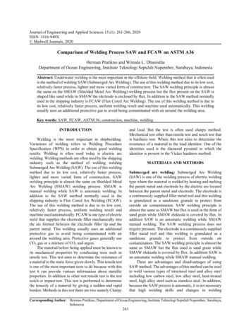
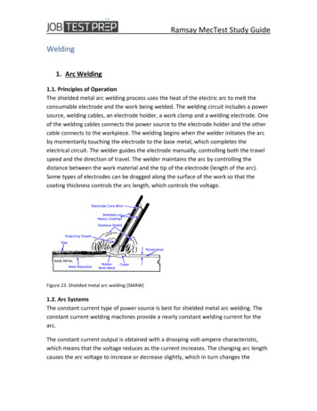
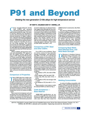
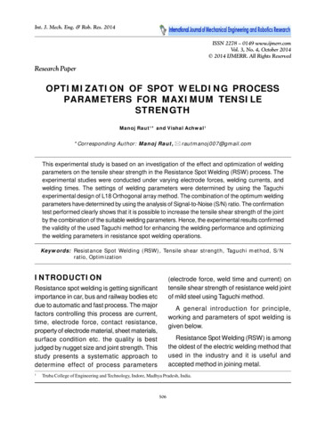
PartChapterSection11.3211Rule Requirements for Materials and WeldingMaterials for Hull ConstructionGeneral Requirements2-1-1Test Specimens Orientation 2-1-1/11.3Tension test specimens are to be taken longitudinal to the final direction of rolling for plates equal toor less than 600 mm (24 in.) in width and transverse to the final direction of rolling for plates widerthan 600 mm (24 in.) except for shapes and bars which are to be taken longitudinal to the finaldirection of rolling.11.5Tension Test Specimens, Plates and Shapes (1996) 2-1-1/11.511.5.1 Flat Specimens 2-1-1/11.5.1Tension test specimens for rolled plates, shapes and flats are to be cut from the finishedmaterial and machined to the form and dimensions referred to in 2-1-1/Figure 1 or tension testspecimens of dimensions other than described may be approved at the request of themanufacturer.11.5.2 Round Specimens 2-1-1/11.5.2For material over 19 mm (0.75 in.) in thickness or diameter, tension test specimens may bemachined to dimensions referred to in 2-1-1/Figure 1. The axis of each round specimen is tobe located as nearly as practicable midway between the center and the surface of the material.Tension test specimens of dimensions other than described above may be approved at therequest of the manufacturer.11.7Tension Test Specimens, Castings and Forgings 2-1-1/11.7Tension test specimens for castings and forgings are to be machined to the form and dimensionsshown in 2-1-1/Figure 2.11.9Bend Test Specimens, Castings and Forgings 2-1-1/11.9When required, bend test specimens for castings and forgings may be machined to 25 mm 12.5 mm(1 in. 0.5 in.) in section, but are not to be less than 12.5 mm 12.5 mm (0.5 in. 0.5 in.) in section.The length is unimportant provided it is enough to perform the bending operation. The sides of thebend test specimens may have the corners rounded to a radius not over 1.5 mm (0.06 in.).11.11 Impact Test Specimens (1996) 2-1-1/11.11An impact test is to consist of three specimens taken from a single test coupon or test location. Impacttest specimens are to be machined to the form, dimensions and tolerances shown in 2-1-1/Figure 3.The largest size specimens possible for the material thickness are to be machined. For plates, flats andbars the specimens are to be located with its edge within 2 mm (0.08 in.) from the surface except thatwhere the thickness exceeds 40 mm (1.57 in.), the longitudinal axis of the specimen is to be located ata point midway between the surface and the center of the thickness. These test specimens are to be cutwith their longitudinal axes either longitudinal or transverse to the final direction of rolling of thematerial at the option of the steel manufacturer, unless a specific orientation is specified. The lengthof the notch is to be perpendicular to the original rolled surface. Also see2-1-2/11.1 and 2-1-4/5.1 as applicable.11.13 Tolerances (1998) 2-1-1/11.13The tolerances of tension test specimen dimensions are to be in accordance with a recognized nationalstandard.8ABS RULE REQUIREMENTS FOR MATERIALS AND WELDING . 2002
PartChapterSection211Rule Requirements for Materials and WeldingMaterials for Hull ConstructionGeneral Requirements13Definition and Determination of Yield Point and YieldStrength 2-1-1/1313.1Yield Point 2-1-1/13.12-1-1The yield point is the first stress in a material, less than the maximum obtainable stress, at which anincrease in strain occurs without an increase in stress. Yield point may be determined by the halt ofthe pointer, or autographic diagram. The 0.5% total extension under load method will also beconsidered acceptable.13.3Yield Strength 2-1-1/13.3The yield strength is the stress at which a material exhibits a specified limiting deviation from theproportionality of stress to strain. Yield strength is to be determined by the 0.2% offset method.Alternatively, for material whose stress-strain characteristics are well known from previous tests inwhich stress-strain diagrams were plotted the 0.5% extension under load method may be used.15Permissible Variations in Dimensions (1994) 2-1-1/1515.1Scope (2002) 2-1-1/15.1The under tolerance specified below represents the minimum material certification requirements andis to be considered as the lower limit of the usual range of variations (plus/minus) from the specifieddimension.The responsibility for meeting the tolerances rests with the manufacturer who is to maintain aprocedure acceptable to the Surveyor. Where any tolerance (including over thickness tolerance) to beused is more stringent than the normal commercial tolerance, the Bureau is to be advised before thesteel is presented for acceptance to assure that the thickness measuring procedure is appropriate.In all cases, the thickness of the steel is to comply with the under tolerance specified below. The steelmill is to consider the effect of mill scale on the resulting measurement.For classification purposes, including the assessment of deterioration at future thickness gaugings, thethickness indicated on the approved plan is to be used.15.3Plates (1996) 2-1-1/15.3The maximum permissible under thickness tolerance for hull steel plates and wide flats of 5 mm(0.20 in.) or more in thickness is 0.3 mm (0.012 in.).The thickness is to be measured at a distance of 10 mm (0.375 in.) or more from the edge.The under thickness tolerance for plates and wide flats less than 5 mm (0.2 in.) in thickness will bespecially considered.15.5Shapes and Bars 2-1-1/15.5The undertolerance of cross sectional dimensions for shapes and bars are based on the ordereddimensions and are to conform to those given in ASTM A6 or other recognized standards as may bespecified in the purchase order.ABS RULE REQUIREMENTS FOR MATERIALS AND WELDING . 20029
PartChapterSection211Rule Requirements for Materials and WeldingMaterials for Hull ConstructionGeneral Requirements2-1-1FIGURE 1Standard Tension Test Specimen (1) (1995)RARound SpecimendaARFlat SpecimendabLoLcAR diameter in mm thickness in mm width in mm gauge length in mm parallel test length in mm cross sectional area in mm2 transition radius in mmbLOLCFlat specimenAlternative AFlat specimenAlternative BRound specimenAlternative Cdab–t (2)25–t (2)2514––LcRLo 2 A2520022525708510Lo5.65ANotes:1210Standard specimen in accordance with ASTM E8/E8M or A370 will also be acceptable in conjunction with thecorresponding elongation requirements in 2-1-2/Table 2 or 2-1-3/Table 2.t is the full thickness of the material as produced. If the capacity of the testing machine does not allow fullthickness specimens to be broken, the thickness may be reduced by machining one surface only.ABS RULE REQUIREMENTS FOR MATERIALS AND WELDING . 2002
PartChapterSection211Rule Requirements for Materials and WeldingMaterials for Hull ConstructionGeneral Requirements2-1-1FIGURE 2Standard Round Tension Test Specimenwith 50 mm (2 in.) Gauge Length (2001)12.5 mm 0.25 mm(0.500 in. 0.010 in.)Reduced Section60 mm (2.25 in.) min.Radius 10 mm(0.375 in.) min.50 mm 0.125 mm(2 in. 0.005 in.)Gauge length for measuringelongation after fractureNote:The gauge length and fillets are to be as shown, but the ends may be of any shape to fit the holdersof the testing machine in such a way that the load is to be axial. The reduced section may have agradual taper from the ends towards the center, with the ends not more than 0.13 mm (0.005 in.)larger in diameter than the center.ABS RULE REQUIREMENTS FOR MATERIALS AND WELDING . 200211
PartChapterSection211Rule Requirements for Materials and WeldingM
ABS RULE REQUIREMENTS FOR MATERIALS AND WELDING .2002 iii PART 2 Foreword For the 1996 edition, the “Rules for Building and Classing Steel Vessels – Part 2: Materials and Welding” was re-titled “Rule Requirements for Materials and Welding – Part 2.”The purpose of this generic title was to emphasize the common app