Transcription
This manual covers all Tecumseh Peerless gear products as follows: 100 Series DifferentialsMST200 Series Transaxles300 Series Transaxles600 Series Transaxles601 Slow Speed Transaxle700 Series Transmissions700H Series Transmissions800/801 Series Transaxles820 Series Transmissions900 Series Transaxles910 Series Transaxles915/940 Series Transaxles920 Series Transaxles930 Series Transaxles1000/1100 Series Right Angle/T-Drives1200 Series Transaxles1300 Series Transaxles2300 Series Transaxles2400 Series Transaxles2500 Series Transaxles2600 Series TransaxlesVST TransaxlesOther illustrated Tecumseh 2-Cycle Engine, 4-Cycle Engine andTransmission manuals; booklets; and wall charts are availablethrough Tecumseh.Tecumseh Products CompanyEngine & Transmission Group900 North StreetGrafton, WI 53024Phone: 262-377-2700FAX: 262-377-4485Tecumseh Europa S.p.A.Strada delle Cacce, 9910135 Torino, ItalyTel. 011 39 11 391-8411Telefax 011 39 11 3910031Litho in U.S.A.H A N D B O O KTECUMSEH & PEERLESS740045www.TecumsehPower.comForm No. 691218 R 3/02T E C H N I C I A N ' STRANSMISSION and DRIVE PRODUCTSFor complete listing write or callENGINES & TRANSMISSIONSTECUMSEHENGINES & TRANSMISSIONS
IMPORTANT NOTICE!SAFETY DEFINITIONSStatements in this manual preceded by the following wordsare of special significance:orWARNING indicates a potentially hazardous situation whichif not avoided, could result in death or serious injury.NOTERefers to important information and is placed in italic type.It is recommended that you take special notice of all itemsdiscussed on each page and wear the appropriate safetyequipment.
TABLE OF CONTENTSPageCHAPTER 1Model Overview and Terms Used . 1 - 6Lubrication Chart . 7Torque Values Chart . 8Identification . 9Trouble Shooting Table . 10 - 12CHAPTER 2300 Series Transaxles . 13CHAPTER 3600 Series Transaxles . 14 - 18601 Slow Speed Transaxle . 19CHAPTER 4700 Series In-Line Shift Transmission . 21 - 25700H Series Transmissions . 26 - 29CHAPTER 5800/801 Series Transaxles . 30 - 36820 Series Transaxles . 37 - 41CHAPTER 6900 Series Transaxles . 42 - 46CHAPTER 7910 Series Transaxles . 47 - 50CHAPTER 8915 Series / 940 Series Transaxles . 51 - 55CHAPTER 9920 Series Transaxles . 56 - 60CHAPTER 10930 Series Transaxles . 61 - 65CHAPTER 11MST200 Series Transaxles . 66 - 70Checking Oil Level. 71CHAPTER 121200 Series Three-Speed Transaxles . 72 - 74CHAPTER 131300 Series Hydrostatic Gear Reduction Differentials . 75 - 77CHAPTER 142300 Series Four-Speed Transaxles . 78 - 84CHAPTER 152400 Series Hydro Powered Transaxles . 85 - 87CHAPTER 162500 Series Hydro Powered Transaxles . 88 - 92CHAPTER 172600 Series Hydro Powered Transaxles . 93 - 97CHAPTER 18Differentials . 98 - 103CHAPTER 19Drives . 104 - 108CHAPTER 201100 Series Drives . 109 - 113CHAPTER 21Shifting Assembly . 114 - 116Shift Key Quick Reference Guide . 117CHAPTER 22Bearing and Bushing Service . 118 - 119CHAPTER 23VST Troubleshooting . 120 - 121CTecumseh Products Company2002
CHAPTER 1. MODEL OVERVIEW AND TERMS USEDTECUMSEH/TRANSMISSIONS UNITSGENERALManufactured since 1945, Tecumseh/Peerless gearproducts are found in many products worldwide.Applications vary from industrial products to residentialand commercial lawn and garden equipment.This book is intended for use by properly trainedtechnicians that have appropriate facilities and the propertools. If you are not a Tecumseh trained technician, DONOT attempt a repair. Consult an Authorized TecumsehServicing Dealer.IDENTIFICATION OF MODELSAll units manufactured since 1964 have identificationnumbers located on an attached tag or are stampedinto the case. This information is required to obtain partsor replacement units. We have included illustrations onpage 9 of this book to assist you in locating them.TRANSAXLESThe term transaxle is a combination transmission anddifferential in one case. Tecumseh transmissions andtransaxles are manufactured in many different gearratio combinations from one to seven forward speedswith one reverse.600 Series The 600 series is a lightweight transaxleused in riding mowers or similar applications. The 600series has a vertical input shaft at the top of the aluminumcase. Variations in the series (which determine thespecific model number such as 603, 603A, 609 etc.)include:1.2.3.4.5.Shift lever shape.Axle lengths.Axle machining for wheel hub attachment.Axle housing variations.Size of the brake shaft.There may be other slight differences, however, theseare present as a result of product improvement whichare not options to an O.E.M. (Original EquipmentManufacturer).800 Series This unit has 3 to 6 speeds forward and 1reverse. This transaxle features bronze oil impregnatedbushings with needle bearings or ball bearings on theaxles, input and output shafts.900 Series This unit is similar to the 800 series transaxlewith the added feature of 2, 3, or 4 speeds forwardand 1 reverse.910 Series The 910 series transaxle offers a forwardand reverse unit. The speed changes with the use of avariable-drive pulley arrangement.915/940 Series This unit has 3 to 5 speeds forwardand 1 reverse. Reverse is gear driven instead of chaindriven and the case is contoured around the gears.920 Series The 920 series offers 3 to 7 speeds forwardand 1 reverse. The shifter/brake shaft is similar to the800 series shifter/brake shaft.930 Series This unit has 3 to 7 speeds forward and 1reverse. The transaxle is very similar to the 920 seriesexcept the differential and shifter/brake shaft are different.The MST Series The MST (Manual Shift Transaxle)is a sealed unit which uses 16 oz. (473 ml) of 80W90gear lube (part #730229B). The MST series is availablewith up to 6 speeds forward and one reverse and hasa contoured case and cover.1200 Series The distinguishing feature of the 1200series transaxle is that the axle support housings arepressed in from the inside of the case and cover. Thereforethey are not readily removable until the unit is completelydisassembled. The case is cast iron for rugged, longtimeuse.2300 Series Generally similar to the 1200 seriestransaxle. The distinguishing features are a more massivecase and a larger shift lever opening machined area.The obvious difference from the standpoint of applicationis that these units have four speeds forward and willbe found on equipment that can be used with groundengagement operations.NOTE: The 1200 and 2300 series transaxles are fairlysimilar in appearance, but do have recognizablecharacteristics. Both of these units have cast ironcases for rugged applications, although the 2300series is the only unit that can be used with groundengaging applications.820 Series With 2 to 6 speeds forward and 1 reverse,this transaxle is built for heavy duty applications includinguse with ground engaging attachments. Sleeved needlebearings are used in place of oil impregnated bushingson all shaft ends and ball bearings are standard onthe axles. The 820 also features steel cut gears formaximum durability.1
HYDROSTATIC GEAR REDUCTION ANDDIFFERENTIAL UNITSGENERALThese units do not have a transmission functioncharacteristic of transaxles, but rather, are designedto reduce input speed to a suitable axle speed andtorque range. The hydrostatic units which mate to theseunits perform the transmission function.1300 Series This unit is the hydrostatic counterpartof the three-speed forward unit (1200). It has an aluminumcasing and pressed-through axle support housings,which is characteristic of the 1200 series. Thehydrostatic pump is made by Eaton Manufacturingand is not serviced by Tecumseh Service Dealers.2400, 2500 & 2600 Series This series of hydrostaticallydriven reduction gear and differential units can be usedin ground engaging operations such as plowing. Thehydrostatic pump is manufactured by Sundstrand Corp.TRANSMISSIONSTransmissions manufactured by Tecumseh consist ofa shifting mechanism to take a constant input shaftspeed and reduce it to the desired output speed.Transmissions need a belt drive or chain drive/differentialassembly to deliver power to the wheels.700 Series This unit can be 2, 3, 4, 5 & 6 speedsforward and 1 reverse. The brake system can be mountedon either side of the unit.700 “H” Series This unit is built with almost allinterchangeable parts within its two cases except withan “H” shift pattern. This unit has 3 or 4 speeds forwardand 1 reverse.DIFFERENTIALSThe 100 series is a self-contained differential/axle unit.It features hardened or non-hardened axle shafts ofvarious lengths and is machined with many variationsfor hub attachment. The case is cast aluminum andthe differential gears are sintered metal (powdered metal)or cut steel. The differential pin is held in place by thefour retaining cap screws. Oil Lite bushings reducefriction during differential operation. The drive sprocketis part of the unit which, depending upon the application,can be of several diameters in size thus having a differentnumber of gear teeth. This sprocket is often suppliedby the O.E.M.ANGLE DRIVESThese units are used primarily to change the directionof drive at the point where the working equipmentattaches. They can be assembled for right or left handrotation so that they can be used in variouscombinations for synchronous operation.2Right Angle Drives These units consist of input shafts,output shafts, and the beveled gearing necessary tochange the direction of power at right angles. If thebevel gear (drive gear) on the input shaft is turned aroundand moved to the other side of the case (opposite endof the shaft), the output shaft will rotate in the oppositedirection.A cover identifies each unit as being either a left hand(LH) or a right hand (RH) right angle drive. The casesand bearings are identical in both drives.“T” Drives The “T” drive is essentially the same asthe right angle drive except that the input shaft extendsout the other side of the case to transmit power in thesame line to additional right angle drives or otherequipment.Shafts, Couplings, Pulleys, etc. These items arepart of complete units and are used to connect angledrives, and other attachments. The serrated couplingsmatch the serrations on the shafts of the angle drivesand connecting shafts.TERMS USEDAXLE - The shaft which connects the wheel or hub tothe differential unit and transmits force back to thewheels.AXLE HOUSING (or AXLE SUPPORT) - An extensionof the case and cover to support the outer ends of theaxles. Because the housing is visible, it is often thebest means of distinguishing the series in question.BEARING BLOCK (Strip) - Used to support the ringgear of the differential.BEVEL (on a gear) This is a chamfer or roundness ofthe meshing side of the gear teeth to permit easyshifting. For instance, with "H" shift pattern transaxles,this is about the only allowance that can be made tomake shifting easier. Input power should be stoppedbefore shifting to keep these spur gears from developingwear.BEVEL GEAR - A gear with teeth ground on a diagonalso that when it meshes with a second bevel gear, poweris transmitted at an angle. If the angle is 90o, the gearis known as a MITER GEAR.BEVEL PINION - The smaller of two meshed bevelgears in a gear train.BRAKESHAFT/SHIFTER BRAKESHAFT) - The shafton a unit (Transaxles or Transmission) to which a brakingsystem may be attached. It is usually larger in diameterthan the input shaft due to its function of taking shockloads experienced in braking.
CASE - That bottom half of the gear box which containsthe shift lever , axle and brake shaft openings. Theother half is the COVER. Unit reassembly is normallydone into the case with variations listed by individualmodel.CHAMFER - In gear products, chamfers provide twomain functions. The first is to reduce gear wear at theleading contact point as two gears mate. The secondpurpose is to act as a ramp for shifter key compressionthrough the shift washer prior to gear engagement.The chamfer in the washer is either stamped ormachined in.COUNTERSHAFT - A splined shaft which hold spurgears that are in constant mesh with shift gears andtransfer input power to the shift gears.COUPLING - A sleeve to connect two serrated or splinedshafts in the same axial plane. Used in right angledrive systems, 700 series, output shafts or in ahydrostatic drive connecting the pump and motor tothe gear drive of a transaxle.COVER - The top half of a horizontally parting gearbox such as 700,800,900 and MST models. The covernormally contains the input shaft, bearing(s) and theinput bevel gear. The shaft may change location inthe cover based on the OEMs mounting position.DIFFERENTIAL GEAR BOLTS - Through bolts holdingthe differential parts together. The heads of these boltsmust be opposite the output shaft gear (except in the2400 series). This is an early check to see that theunit is being assembled correctly.DOWEL PIN - An alignment pin used to align the caseand cover and other parts in a transmission or transaxle.The dowel pins should be installed to hold the parts inalignment before tightening the retaining screws. Failureto install dowel pins first will usually lead to a unit thatbinds after assembly.DUO-TRAK DIFFERENTIAL (Trademark -IllinoisTool Works) - A type of differential which increasestorque to the tractive wheel to keep it turning. Howeverin situations where differentiation is necessary (as inturning), the unit acts much like a regular differential.EQUIPMENT - The complete assembled product (ridingmower, tractor etc.) which uses of the drives listed inthis manual.HEAD ASSEMBLY - A complete unit containing allparts of one right angle or “T” drive assembly of a rightangle drive system. The head assembly is permanentlylubricated and sealed.IDENTIFICATION NUMBER - See MODEL NUMBERIDLER - A gear used in a gear train to transfer motionor direction. The gear rotates independently of the shaftupon which it is located.INPUT OR INPUT SHAFT - The part of a unit which isalways connected to the drive. Its rotational speed isdependent on the driving mechanism. The input shaftbrings power to the unit.LIMITED SLIP DIFFERENTIAL - See DUOTRAK DIFFERENTIAL.MITER GEAR - One of a pair of interchangeable bevelgears with axles at right angles. Since all bevel gearsare miter gears, the terms can be the same.MODEL NUMBER - The identifying number of a unitwhich will permit selection of the proper parts to repairthat unit.NEUTRAL SPACER - A single or split collar betweenforward and reverse gears that the shift keys engageinto when the unit is in neutral.OIL SEAL, SINGLE LIP/DOUBLE LIP - An oil sealwith one or two sealing surfaces to prevent entranceof foreign matter and leakage of lubricant.OIL SEAL, (SQUARE CUT O-RING)- A seal with twoexternal and two internal sealing surfaces. Used inthe shifter housing.OUTPUT, OR OUTPUT SHAFT - On a transaxle, theshaft that contains the output pinion which is in directmesh with and drives the differential. The output shafton a transmission contains the sprocket for drivingthe axles. The output shaft is driven by the large OUTPUTGEAR.OUTPUT SHAFT GEAR - The importance of definingthis gear is to point out that it must be opposite thedifferential bull gear (except the 2400 series).GEAR REDUCTION AND DIFFERENTIAL UNIT - Aunit that reduces a high R.P.M. input speed to a suitableaxle speed without the use of a transmission. Sincethere is a single gear train, there is a single inputspeed to output speed ratio, however, axle speedsare infinite, depending upon input speed.REVERSE IDLER (915 Series) - The gear locatedbetween the reverse gear of the countershaft and thereverse gear of the shifter/brake shaft that allows thedrive to operate in the opposite direction.REVERSE IDLER - A gear added to the gear train sowhen in mesh, the direction of all gears driven after itis reversed. Its number of teeth also affects the reversegear ratio. The center gear of the three gear cluster isalways in mesh with the REVERSE IDLER, and thelarge shifter gear always shifts into it.RIGHT ANGLE DRIVE / HEAD ASSEMBLY. The majoroperating parts are a pair of miter gears. The assemblyconsists of other right angle or “T” drive head assembliesand connecting hardware.3
SEAL - A material which prevents lubricant from leakingpast a rotating shaft. It can be a rubber or square cut"O"-ring, a sealing-type ball bearing, or most commonly,a rubber sealing surface encased in a metal form.SEAL RETAINER - Found on some models of transaxlesand on right angle drives.SHIFTER HOUSING (600/2300's) - This housingcontains the shift lever and must be re-installed in theproper position to function correctly. If the housing doesnot already have guide marks, scribe the shifter housingand transmission case before removal.SHIFT COLLAR - A round collar which retains shiftkeys onto the shifter/brake shaft. The shifter assemblypin (or pins) slide into the groove on the collar to movethe shift keys.SHIFTER ROD - One of two similar smooth rods ofequal length with grooves which match the forkpositioning with meshed positions of the shifter gearsand those of the three gear cluster. Each rod has asnap ring to act as a fork stop, but can also be usedto determine how the fork is assembled to it.SHIFT GEARS - The gears on the shifter/brake shaftthat are in constant mesh with the spur gears of thecounter shaft. The shift gear is engaged by the shiftkeys and it's size determines the speed of output bythe axles.SHIFTER SHAFT - A splined shaft which meshes withthe internal splines of the shifter gears, to transmitforce to the output shaft gear. On in-line transmissionsand transaxles the shaft has machined channels toaccommodate the shift keys.SHIFT KEY - One of either two or four metal springsteel keys, which are held in the keyways of the shifter/brake shaft by a shift collar. The shift keys are usedto slide through the shift gears and engage the desiredgear or speed.SHIFTER STOP (600/2300's) - A stamped metal platewhich separates the shifter forks. The stop has a notchcut in it which corresponds to the neutral position onthe shifter forks and rod. The shifter lever must returnthe engaged fork back to neutral before it can actuatethe other fork.SHIFT KEYWAY - One of either two or four slots inthe shifter/brake shaft for the shift keys to slide throughfor gear selection.SHIFT WASHER - The shift washer provides a rampto gradually compress the shift key prior to engagementwith the gear. We have used two types in production;the newer style has the chamfer stamped into thewasher. Earlier production washer’s had the chamfermachined in.SHIFTER ASSEMBLY - Consists of a shift rod, shiftfan, shift arms and shift pin or pins.SHIFT LEVER - The lever by which the operator manuallychanges the shifter gears to vary reduction speed ratiosin the transmission. The configuration of the lever isvariable and is often the only reason for a unit beinggiven a new model number.SHIFTER FORK - A mechanical arm which is connectedto the shifter rod to position the shifter gear at an exactspot axially along the shifter shaft.SHIFTER GEAR, LARGE (600/2300) - This geartransmits 1st gear, reverse gear (and 2nd gear in 4speed units) ratio force to the output shaft. It is beveledon both sides.SHIFTER GEAR, SMALL (600/2300) - This geartransmits 2nd and 3rd (3rd and 4th in a 4-speed unit)gear ratio force to the output shaft. It can have twodifferent beveled tooth diameters or it can have a beveledspline to engage 3rd (or 4th) gear through an additionalsplined shaft.SPROCKET - A geared wheel designed to turn a chaindrive. Sprocket diameters vary and are available indifferent sizes for changing output ratios.SPUR GEAR - A gear having the shaft bore and teethin a parallel plane.“T” DRIVE - A right angle drive with an input shaftextending thru the case to transmit power axially in asecond direction to the right angle output. On “T” driveswith dissimilar input and output ends, care must betaken to insure that the parts do not run in reversewhen reassembled.THREE GEAR CLUSTER (2300) - A three gear assemblyin mesh with the input shaft. The gears are of differentsizes to change gear ratios when meshing with thetwo shifter gears.THRUSTER RACE - A thrust washer in which the outeredge is cupped to fit the outer diameter of a thrustbearing. This fit positions the thrust race concentricwith the axle diameter. It further acts as a thrust washer.THRUST WASHER - A flat polished surface separatingmetals of different hardness. It also acts as a spacerbetween shafts and the case and cover.TRANSMISSION - A system of varying sized gearsin a case, some of which can be moved along a shaftto vary the gear ratio in a unit. The net effect is tochange speeds to the rear wheel according to the typeof work being done.UNIT - A general term for Tecumseh/PeerlessTransmission products.4
GENERAL SERVICING PROCEDURESThe following service procedures should be understoodand practiced whenever service is needed on aTecumseh transmission or drive product.WARNING It is recommended that you takespecial notice of all itemsdiscussed in this manual and wear the appropriatesafety equipment. Failure to do so may result indeath or serious injury.Use approved safety procedureswith equipment for removal/installation of axles, keyways and hardened shafts.Remove all burrs and sharp edges with a honingstone or crocus cloth before installation. Failureto do so could result in equipment damage, deathor serious injury.WARNINGBefore removing a unit (Transmission product) fromany equipment, look for and ask the customer about:1. Loose, worn or glazed drive belts.2. A misadjusted or badly worn clutch or belt tension.3. Loose/lost set screws and or sheared keys in drive,driven pulleys or axle.4. Oil saturated drive belts or clutches.5. Bad operating habits, such as clutch riding or notclutching when shifting.6. Oil leaks.7. If possible operate the equipment to help isolatethe problem.8. Review Service Bulletin 304.Removal of the unit from the equipment:3. Remove the shift housing and drain the lubricantfrom unit. Observe the old lubricant to see if metalparticles are present.4. Check axle shafts carefully for smoothness. Usecrocus cloth or a Scotch-Bright pad to rub downhigh spots and eliminate rust or paint from the shafts.5. Check the model and specification number andremember to have the exploded parts diagramaccessible during disassembly.6. Have on hand seal protectors, drivers, shop cloths,appropriate tools and this technicians handbookwhile servicing a unit.OIL LEAKS, SEAL AND GASKET SERVICETecumseh units contain various styles and sizes ofoil seals. The function of any oil seal is to seal inwardto prevent lubricant leaks and prevent outside debrisfrom entering the unit. Seals can be single lippedwith the sealing edge facing inward or double lippedsealing inside and out.GUIDELINES TO REMEMBER1. Other than leaking seals, gaskets and “O” rings,leakage can occur due to a cracked case or cover,flats on shafts, porosity (rarely, if ever), and wornbushings and shafts.2. Replace ALL seals/gaskets if disturbed. The smallcost of installing new seals is small in comparisonto a dissatisfied customer and the cost of rework.3. Some seals have a "Redicoat" sealant applied,while others may need a thin coat of RTV siliconeto the outer shell upon installation.1. Raise the equipment so the transmission or transaxleis accessible. Use wood blocks to preventequipment from shifting. Do not use bricks, cementor cinder blocks.2. Visually inspect the Tecumseh unit for oil leaks, acracked housing, binding or rubbing of parts, orother symptoms of malfunction.3. Use a jack under the unit to support it’s weightwhen attachments are removed.4. Remove wheels, drive belts, pulleys, chains andother associated equipment from the unit. Be awareof positioning of parts. Use a scribe mark, if indoubt, to reassemble parts quickly and accurately.5. If the shifter lever will interfere with removal of theunit in anyway, remove it before unit removal. Thesecan easily be bend out of shape.6. Remove all attached hardware holding theTecumseh/Transmission unit to the equipment onthe case, cover, axle supports, brake and shifter.7. Remove the unit from the equipment.4. The surface over which the seal makes contactmust be free of all cuts, scratches, high spots andrust. The shafts should be smooth, shiny and athin film of light oil applied. Seal protectors mustbe used to clear keyways, splines, or other machinedsharp edges on the shafts.Preparing for disassembly of a unit:Under-tightening fasteners can cause oil leakage,loosening of attaching parts, and possible shifting ofthe internal parts which may bring about a completefailure.1. Visually inspect for evidence of oil seepage,tampering, misalignment, freedom of rotating shafts,etc.2. Clean the unit thoroughly of any dirt, oil and debris.TORQUE VALUE TROUBLESHOOTINGGUIDELINESALWAYS torque all fasteners to the appropriate valueas listed in Chapter 1 page 9.Over-tightening can strip the threads in the cases oron a fastener. It also can over-compress gaskets,and possibly cause binding in the unit.A cross-tightening sequence to half the torque thenfinally to full torque value is a recommended procedureto prevent comebacks (repair returns).5
BASIC TESTINGThe absence of binding and oil leakage are the bestindications that the unit has been properly reassembled.Though other, more elaborate tests can be done, thefollowing procedures are accurate and the preferredmethod for a quick check of the unit.On an "H" shift pattern drive with the shift forks inneutral, rotate both axle ends in the same direction.They should turn smoothly although a little effort maybe necessary. The brake shaft should rotate wheneverthe axles turn together, but in neutral, the input shaftshould not turn. By moving any shifter gear into mesh,a greater drag should be felt on the axles, and boththe input and brakeshaft should turn. For ease in turningthe various shafts, insert a tool (such as a punch or asocket head screw key) into the keyway, however, donot force if the shaft is binding.Potential reasons for binding in the unit could be:1. Gaskets were left out on reassembly or installedincorrectly.2. Oil seal retainers, differential, thrust washers, shifterstop or oil seal retainers were installed improperly.3. The shifter assembly or spacers were installedincorrectly.4. Foreign matter could be blocking the gear teeththat are in mesh.5. The input shaft was not properly seated in the case.6. The case and cover could be mis-aligned (dowelpins were missing).7. The bearing(s) do not have the lock tabs or notchesin the correct position.For more information, consult the troubleshootingsection.6
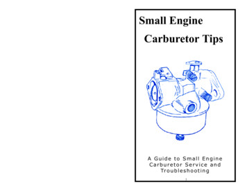
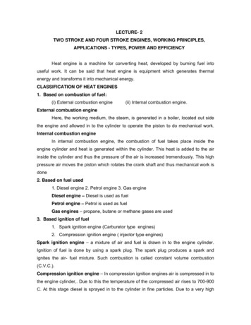
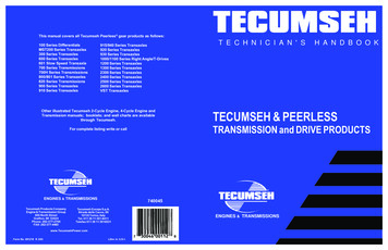
LUBRICATION CHARTCheck the Transmissions unit model and specification number before filling with lubricant. There may be adifference in the quantity recommended. This is dictated by the design of the vehicle and position of thetransmission unit 291319132313261327MST23002
Engine & Transmission Group 900 North Street Grafton, WI 53024 Phone: 262-377-2700 FAX: 262-377-4485 Tecumseh Europa S.p.A. Strada delle Cacce, 99 10135 Torino, Italy Tel. 011 39 11 391-8411 Telefax 011 39 11 3910031 ENGINES & TRANSMISSIONS www.TecumsehPower.com TECUMSEH &