Transcription
Heat Staking Design Guide: InsertingMetal into Plastic with Induction
» Table ofCONTENTSINTRODUCTION . 3BASICS OF METAL-TO-PLASTIC BONDING . 7SIMULTANEOUS HEAT STAKING OF 3 STEEL INSERTS.11INSERTING METAL PARTS ACCURATELY.12STAKING STEEL INSERTS INTO A CHAIR FRAME.13ATTACHING PLASTIC HANDLES TO STEEL FLATWARE .14STAKING PLASTIC BEARINGS ON STEEL SHAFTS.14BONDING ELECTRICAL CONNECTOR COMPONENTS.15INSERTING PLASTIC HANDLES INTO METAL CONTROL ARMS .16HEAT STAKING LARGE BRASS INSERTS .17AMBRELL POWER SUPPLIES . 18COMPLIMENTARY APPLICATIONS TESTING . 19ABOUT AMBRELL . 202Heat Staking: Inserting Metal into PlasticISO EmblemUsing InductionContactProducts
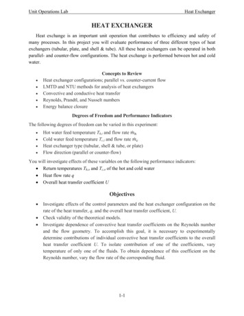
» Introduction: Heat StakingBasic Design GuidelinesOne of the most common uses for induction heating isthe heat staking of threaded metal inserts into plastic.Most thermoplastics are too soft to sufficiently hold athread, so brass or steel threaded inserts are added.Post-molded installation is more cost-effective thanmolding in place and induction is a proven way topre-heat the inserts prior to installation.For heat staking, the insert is preheated with inductionand then pressed into a hole in the plastic part. This isaccomplished by positioning the induction coil over thehole and then holding the insert in the coil for a shortperiod of time. When the correct temperature is achieved,the insert is pressed into the plastic. A narrow zone ofplastic then melts and flows into the knurls of the insert.The plastic re-solidifies, resulting in a complete assemblywith much better mechanical properties than insertsimplanted with other techniques.The insert material is usually brass or steel; each hasadvantages and disadvantages. Brass is non-magneticand will not corrode as easily as steel. However, brassis a softer material and will anneal at temperatures aslow as 450 F, whereas steel starts to anneal at 1200 F.3
» Introduction:Heat Staking Basic Design GuidelinesSome glass-filled plastics require inserts to be heatedto 700 F for correct installation, so the brass insertsmust be heated and inserted quickly to prevent threadannealing. Brass has low electrical resistivity andtherefore requires more power to heat with inductionthan steel.A steel insert can be heated more quickly because steelhas high resistivity and is harder than brass, and there isno concern about annealing at the insertion temperatureof most plastics. However, consistent coating or platedfinishing of steel inserts, particularly in the threads, canbe difficult to achieve because steel inserts are typicallymagnetic and oxidize more quickly than brass. Theselection of the insert material is dependent on thespecific application requirements, but brass is often thematerial of choice due to the coating and plating issues.Figure 1: Insert is preheated withinduction and then pressed into ahole in the plastic part.There are also other factors to consider: the insert must have the proper knurland fin design to achieve the desired rotational torque and tensile strength. Mostinserts designed for molded-in, expansion, ultrasonic or self-threading insertioncan be used with the induction heating process. However, due to the inductivelyheated insert’s ability to easily re-flow plastic, the knurls and fin on the insert canbe made deeper for greater holding strength. The material and mass of the insert,together with the available heating time, will determine the power required toreach the desired temperature.The installation temperature of the insert is important. Each insert must be heatedto the same temperature in the same time to achieve a consistent process.What Affects Consistency in the Induction Heat Staking Process?Power-on cycle in the induction power supplyHeat-on timeTuning frequencyPower ramp-up and ramp-downPositioning of the insert in the coilInsertion pressureThermoplastic material Figure 2: Different insert types.4Heat Staking: Inserting Metal into PlasticISO EmblemUsing InductionContactProducts
» Introduction:Heat Staking Basic Design GuidelinesThermoplastics will flow at elevated temperatures and the solidified polymer can be re-heated to re-flow around the insert.Thermosetting polymers, once the shape has been cast, will no longer melt or flow on reheating. Table 1 shows some typicaltemperatures, time and power required for different materials, as established in the Ambrell Applications Lab.The diameter of the insert hole must be the correct size to allow the plastic to flow around the insert. If the hole is too small,extra plastic will be displaced. This displaced plastic is commonly called ‘flash.’ Excessive heat and pressure may also causeflash. If the hole is too large, not enough plastic will flow into the fins and knurls to achieve the desired holding strength.With proper fixturing, tight center-to-center tolerances of the inserts can be maintained. Although molded plastic partssometimes do not have tight tolerance, post-molded installation with induction heating and accurate insert location toolingwill put the insert in the same location each time, even if the holes in the plastic vary in size.Table 1: Typical heating times, temperatures and power required for different materialsQty.MaterialInsert Size; Ø,lg (in)Temp ( F)Time (sec)Power (kW)Model (kW)1brass.33, .50, .17 wall4001.311brass.33, .50, .10 wall400.8.311brass.25, .634002.51.234steel.63, .50, .12 wall50012.612brass.25, .50, .12 wall3502.811brass.56, 1.257006.811steel.75, .052502.71There are several methods used for inserting withinduction heat. An x - y positioning table (see Figure 3)can be used in conjunction with a single position coilwhen multiple inserts need to be installed in a singlemolded part. The position of the coil is held constantand the x - y table moves each insert location under orabove the coil. This technique provides for a flexiblemanufacturing tool that can be changed by softwareprogramming rather than hardware tooling changes.Figure 3: Stationary inserter, variable “X” and “Y” table.5
» Introduction:Heat Staking Basic Design GuidelinesAs shown in Figure 4, a second option for a single position coil is the use of a robotic arm. The plastic part is heldin fixed location while the coil and indexing mechanism can be moved to each insert location. Encapsulated heatstations are available from Ambrell for this purpose. Small encapsulated heat stations can be supplied with 1, 3,5 and 7.5 kW power supplies with mounting brackets to align with robotic insertion tooling. Location of the coilrelative to the heat station is custom-designed for each application.A multiple-position coil makes it possible to install more than one insert at a time into a single plastic part.Three- and four-position coils have been used for this application. For this setup, the coil is normally in a fixedposition and the plastic part is moved into the coil. The inserts for each location are heated simultaneously andthen pressed into the plastic.For all tooling arrangements with induction heat, the manner in which the insert is held is more important thanwith other insertion methods. Using metallic tools to hold the insert in the coil will impede the performance of theinduction power supply. Any tooling in direct contact with the inserts should be nonmagnetic and have thesmallest mass possible. Non-magnetic stainless steel is often used for the rod which locates and inserts the part.The insert threads should not be used for holding, as this can damage the threads during insertion. Three jawchucks or a combination of a locating rod and vacuum can be used for holding the insert. With each method, ataper or some other centering mechanism should be incorporated into the design. Gravity is often used to positionthe inserts onto the insert tooling, and the inserts are normally pushed upward or horizontally into the plastic.Figure 4: Stationary table, variable position inserter.6Heat Staking: Inserting Metal into PlasticISO EmblemUsing InductionContactProducts
» The Heat Staking Process:Basics of Metal-to-Plastic BondingWhich metal should I use for induction heat staking?Since steel, brass and aluminum are the materials of choice for metal inserts for plasticbonding, let us look at the relative merits of each material and see how each characteristic affects the ability of the material to be heated and inserted into the plastic part.Material resistivity, permeability, specific heat and thermal conductivity are the fourprimary properties to consider when heating a metal insert with induction. Each of thesematerials can be heated by induction, but the individual material properties will dictatethe characteristics of the induction process. Table 2 shows the characteristics of 3/8" ODinserts made from steel, brass and aluminum when heated with the same magnetic fieldproduced by a coil with the same current passing through it and the same number ofturns. The steel insert absorbs more power from the magnetic field so it is heated fasterthan the aluminum and brass inserts. The induction process produces heat in the insertby creating an electrical current that flows around the part. This induced current flowsthrough the resistivity of the material causing heat to be generated within the insert.The current flows towards the outside surface of the part with most (80%) of it flowingin an area known as the skin depth. The skin depth is dependent on the resistivity andpermeability properties of the material. Table 2 shows the steel insert with a skin depth of0.0025", compared to the brass of .008", showing that the heat induced in the steel partis produced in an area 2.5 thousandths of an inch in from the surface, while the brass is8 thousandths of an inch. This has several effects on the induction process. With a steelinsert, the heat is produced closer to the edge, so care must be taken not to melt theouter surface during fast heating cycles. The heating time must be long enough to allowsufficient energy to be transferred to the insert to allow for proper bonding when insertedinto the plastic. The .008” skin depth of the brass insert produces the heat more into thepart but dictates that small diameter inserts must be heated with higher frequencies tomaintain heating efficiency.Table 2: 3/8" OD inserts in same magnetic field in a coil with same number ofturns and same current.ResistivitySkin depthSpecific heatThermal eelunits1.112.7629.0µΩ inch0.0050.0080.0025in0.2140.0920.118Cal/gm C21139552350350350 F3.23.01.1secFor optimum efficiency, the diameterof the insert must be greater than4x the skin depth. The skin depth isgiven by the fundamental equation:where:d the skin depth in inchesρ the resistivity in mΩ-inchesμ the permeability of the metalƒ the operating frequency (Hz).This formula dictates that in orderto achieve efficient heating for smallinserts, the operating frequencyof the induction equipment mustbe above 50 kHz. When takinginto account the overall size of theinsert, the available insert length foran effective coil and the resultingsmall number of turns and low coilinductance, operating frequencies inthe 300 to 450 kHz are required forefficient coil/part energy transfer.The amount of energy required toheat the insert depends on the massof the insert and on the specific heatof the material described by the following equation:where:Q quantity of heat (kW)Cp specific heat (BTU/lb F)ΔT rise in temperature ( F)m mass (lbs./minute)7
» The Heat Staking Process:Basics of Metal-to-Plastic BondingThe power required by the insert is indirectly relatedto the time taken to heat it. If the heating time isincreased from one second to three seconds, theamount of power required would decrease to 205watts. Although the power required to heat the brassand aluminum inserts is less than steel, the powerabsorbed from the magnetic field as shown in Table2 is far less than the steel insert. So the steel partsheat much more efficiently than the brass oraluminum and require much less power from thepower supply.Figure 5: Temperature through the cross section of the steelinsert, 3/8” OD. A specially designed 4-turn double wound helicalcoil is used on the 1 kW power supply for the heating.This means that, with the properly designedinduction coil, a 1 kW induction power supply canbe used to heat one aluminum insert, two brassinserts or three steel inserts at a time.Having looked at the material properties affectingthe heating cycle, let us now look at the materialcharacteristics which affect the insertion process.Specific heat and thermal conductivity are theprimary properties to consider. Since the inductionprocess produces heat towards the outside of themetal part, the heating pattern should be consideredrelative to the process time.At the end of the heating cycle the surface of theinsert is at a relatively higher temperature than theinside. However, due to the thermal conductivity ofthese materials, the insert quickly reaches a uniformtemperature throughout. When the 3/8" OD of a brassinsert is heated to 3500 F in one second, it will onlytake 60 milliseconds for the center thread surface toreach temperature equilibrium. The steel insert willtake 25 milliseconds. A short heat cycle and dwelltime prior to insertion will minimize the possibility ofthread annealing.Figure 6: Temperature through the cross section of the brass insert,3/8” OD. A specially designed 4-turn double wound helical coil isused on the 1 kW power supply for heating.Aluminum BrassSteelunitsMass0.00580.01840.0165lbsSpecific heat0.2140.0920.118Temperature rise300300300 FPower required390535615WTable 3: The amount of power required to heat 3/8 inchdiameter inserts to 350 F in one second.8Heat Staking: Inserting Metal into PlasticISO EmblemUsing InductionContactProducts
» The Heat Staking Process:Basics of Metal-to-Plastic BondingAfter the heating cycle, during the insert locationand before the actual insertion, the insert loses heatby radiation and convection. Heat is also lost to thefixture holding the insert. As shown in Figure 7, thedrop in surface temperature is almost exponential. Itis therefore important that the insert is pushed intothe plastic as soon as possible after the end of theheating cycle. A brass insert must be inserted withinfive seconds of the end of the heating cycle; otherwise the insert will have lost sufficient heat to meltand flow the plastic.Figure 7 also shows the surface temperature ofthe insert when it is pushed into the plastic. Thetemperature of the insert drops much more rapidlyafter insertion because it looses heat in melting theplastic and by conduction into the plastic. A comparable curve for steel is shown in Figure 8. Steel insertscan be heated very quickly; due to the poor thermalconductivity of steel and the surface temperature ofsteel will be at a much higher temperature than thecenter of the insert. As seen in Figure 8, at the endof the heating cycle the temperature of the surface ofthe insert drops rapidly as the heat travels through tothe center of the insert until the whole insert reachesthe equilibrium temperature (400 F).Figure 7: Temperature of a 3/8" brass insert in air and when inserted in plastic. The insert is heated for 1.0 seconds and shouldbe inserted within 5 seconds to obtain good capture of the plasticaround the insert.The heat content of the metal insert just before it ispushed in the polymer should be sufficient to meltthe polymer to a plastic state and have a good flowaround the insert. The interference between the insertand the guiding bore in the polymer determines theamount of polymer to be displaced. It is usually notenough just to heat the insert to the melting point ofthe plastic.Figure 8: Temperature of a 3/8" steel insert in air and wheninserted in plastic. The insert is heated for only 0.4 seconds andthen inserted within 3 seconds to obtain good capture of plasticaround the insert.The insert has to be sufficiently heated so that theheat content stored in the insert is enough to raisethe temperature of the polymer at the interface to themelting temperature, and also have enough heat toovercome the latent heat of fusion of the polymer.The latent heat of a substance is the amount of heatrequired at the melting temperature to change thephase from solid to liquid. This depends on the particular plastic used. Abrass insert at 350 F could not be inserted into a plastic which melts atabout 200–250 F. The insert must be heated to a temperature of about400 F to get a good insertion. The insert must be heated to a temperaturehigher than the melting temperature of the plastic to get a good flow ofplastic around it. Yet, the insert must not be too hot; or the plastic will burnor boil creating excessive flashing.9
» The Heat Staking Process:Basics of Metal-to-Plastic BondingHow to Improve Induction Heat Staking Process EfficiencyOnce the insert has been pushed in the polymer, a temperature gradient arises in the polymer; the temperature ishottest at the insert/polymer interface and drops exponentially away from it. The locating fixture should be heldstationary after insertion for the polymer to re-solidify around the insert. For the 3/8" brass insert, a hold time of0.5 seconds is usually sufficient to allow the plastic enough time to re-solidify to maintain the tolerance required bythe insert. The hold time depends on a number of factors: the insert material, the insert temperature at the time ofinsertion, the amount of polymer displaced and the temperature characteristics of the polymer. The melting point andviscosity of the polymer will determine the required temperature for satisfactory insertion.The process of staking the metal insert into the plastic depends upon the material characteristics of both theinsert and the plastic. During the heating process, a proper coil design (see Figure 9) is required to transfer powerefficiently and quickly to the insert. Although steel is easiest to heat, brass or aluminum can also be used. With a1 kW power supply, only one aluminum insert can be heated, where two of brass and three of steel can be heated inthe same time using properly designed coils. Cycle times can therefore be reduced by using steel or brass inserts.The insert must be heated to a temperature higher than the melting temperature of the plastic, and the insert mustbe pushed into the plastic within two to five seconds depending on the size of the insert. Heat lost by radiation andconvection, as well as the heat lost by conduction to the inserting fixture, must be accounted for in the design of theprocess. A good capture of plastic is vital for good pull strength and resistance to torque. Thus, the optimum insertion process depends on a properly designed coil, metal insert and the guiding hole. The insert must also be heatedto the right temperature to have a good strong product with good capture of plastic around the metal insert.Figure 9: Typical coil design and positioning for heat staking.10Heat Staking: Inserting Metal into PlasticISO EmblemUsing InductionContactProducts
» Simultaneous Heat Staking of Three Steel InsertsThere are many plastic molding applications that require an assembly with two or three inserts. By simultaneouslyheating the inserts with induction in a multi-position coil, the inserts can be pushed into the part at the same time,optimizing throughput and yield.An automotive door handle required three steel inserts to be placed in three separate locations on the handle. Allthree locations were on different plains, but were inserted from the same side. The steel inserts are relatively easyto heat with induction energy, so a multi-position coil designed for the same hole positions as the inserts on thehandle will heat the three steel parts to 375 F in 2 seconds. The coil is in a single plane and the insert push rods aredesigned to correctly place each insert into the door handle on a five-second cycle time. These steel inserts have a0.5” diameter flange which has to seat on the door handle, but not melt into the surface.By designing the coil correctly and properly positioning the part in the coil, the body of the insert can be heated to ahigher temperature than the flange.11
» Inserting Metal Parts AccuratelyIt is often necessary to locate the metal inserts in the molded plastic part with greater accuracy than is achievablewith ultrasonic insertion techniques. Errors in the precise location of the holes in some plastic moldings cause partsinserted ultrasonically to “wander” from the required location.By using induction heating to heat the insert, and with accurate insert location, inserts can be positioned to correctthe location errors in the holes in the molded part. As the heated insert causes the plastic to melt and flow, 0.03 to0.10 inch correction in the location of the insert is achievable.In the application illustrated in Figure 11, an air nozzle required two inserts to be accurately positioned relative toone face independent of the molded hole spacing. By accurately locating the insert push rods relative to the part, theinserts could be precisely inserted into the molding with a loosely coupled two-position coil. A 1 kW Ambrell solidstate power supply was used for this application. Heating the two inserts produced a total cycle time of one part inevery five seconds, with the insertion and cure time taking an additional three seconds. The inserts were heated to350 F and the system operated at a frequency of 207 kHz with 275 watts loaded into both inserts.Figure 11: Accurate insertion of metal parts with precision induction heating.12Heat Staking: Inserting Metal into PlasticISO EmblemUsing InductionContactProducts
» Staking Steel Inserts into a Chair FrameStandard office chairs often have a metal leg assembly with a molded plastic body attached with steelfasteners. Metal inserts are screwed into the plastic chair body, with the leg assembly bolting to it.Unfortunately, the retention and torque strength of the threaded metal inserts is not very reliable, andthe assemblies tend to loosen over time.When induction is used to heat the insert, the insert becomes an integral part of the plastic chairbody. The steel insert is heated to a temperature high enough to melt the plastic upon insertion. Theplastic re-flows around the knurls, cures, and forms a lasting bond. Once it has cured, the retentionand torque strength is extremely high, and the process can be duplicated quickly and consistently.In the application illustrated below, four steel inserts are heated simultaneously with a multi-turn,multi-position coil. The inserts are positioned in the coil using nonmagnetic stainless steel push rods;and are heated to 600 F in approximately thirteen seconds, before insertion into the 30% glass-filledplastic chair body at 490 F. The induction heating insert process has a much higher retention strengthand positional accuracy than can be achieved with the threading process.Figure 12: Setup for heat staking steel inserts into a plastic office chair frame.13
» Attaching Plastic Handles to Steel FlatwareThe cutlery industry has many requirements for attaching plastic handles on steel flatware. Many types ofpocket knives, dinner knives, forks and spoons incorporate plastic handles. Induction heat is used to heat thetang of the flatware either before or after attaching the plastic handle.In one application, a plastic handle was positioned on a pancake coil and the flatware tang aligned at the end ofthe handle (opposite end of the coil). Power was applied to the coil and the tang/ handle assembly was movedinto the coil center position. The tang was pushed into the handle as the ABS melted, and the entire assemblywas removed from the coil as the tang fully seated. The time to complete the operation was four seconds.This application required a frequency of 270 kHz and 200 watts of power to raise the tang temperature toapproximately 350 F. This allowed the plastic to form correctly around the tang, but was not so much heat thatthe handle lost its molded shape. The pancake coil design was used so the staking process could be directlyincorporated into the assembly line.» Staking Plastic Bearings on Steel ShaftsWith the advances in polymer applications for bearingsurfaces, there are many applications which involve theattachment of a bearing assembly to a steel shaft. Inthe automotive industry, plastic bearing assemblies areoften used on the end of air spring cylinders to aid theopening of hoods and trunks.In the application illustrated in Figure 14, the ends oftwo steel shafts were simultaneously heated in amulti-position coil with a 3 kW power supply and anencapsulated remote heat station. The heat station andcoil assembly moved over the two steel shafts andheated the ends of the shafts to 1300 F in less thantwo seconds before moving back from the shafts.The plastic bearing assemblies were placed on theends of the shafts, 880 watts of power was delivered toeach end, and the total cycle time was approximately15 seconds. The high temperature of the ends to allowfor cooling after the shafts have been removed fromthe coil, the coil moved back and the plastic bearingsinserted.Figure 14: Setup for staking plastic bearings on steel shafts.By keeping the steel shaft and the bearing in one verticalplane, and moving the coil and encapsulated heat stationfor the heat cycle, a more reliable automated processwas achieved.14Heat Staking: Inserting Metal into PlasticISO EmblemUsing InductionContactProducts
» Bonding Electrical Connector ComponentsMany two-part electrical connectors are held together using a mechanical threaded screw.0.25 inch OD brass inserts are often used to provide the robust thread in the plastic connector body andinduction heating can be used to heat these with precision and consistency.Figure 15 illustrates how a 0.25” OD 0.625” long brass insert is heated to 600 F in two seconds prior toinsertion in the glass-filled plastic connector housing. 1225 watts is delivered to the part from a 3 kWinduction power supply.Since the hole in the connector is a through hole rather than the usual blind hole, a guide rod can passthrough the plastic housing to help guide and correctly locate the insert in the housing.Figure 15: Setup for bonding electrical connector housing components.15
» Inserting Plastic Handles into Metal Control ArmsAgriculture and yard care equipment often have metal control arms with plastic handles. The plastic handlesare threaded onto the metal control arms which can eventually loosen, and could become a safety concernif the handle were missing or broken due to continuous adjustment. With induction heating, the moldedhandle and metal assembly can be permanently fused together with a better torque strength than can beachieved with the simple threading technique.During manufacture each control arm/handle assembly is processed with the same coil and power supply,using different heating times as necessary. A control arm is inserted into its corresponding handle and theassembly placed over the coil. Power is applied and the handle pressed onto the control arm as heatingoccurs. In one lab application, the steel control arm reached a temperature of approximately 400 F andheating times varied from two to six seconds depending on the assembly.Figure 16: Fixturing table for inserting large brass inserts into engine manifold.16Heat Staking: Inserting Metal into PlasticISO EmblemUsing InductionContactProducts
» Heat Staking Large Brass InsertsAutomobile inlet manifolds are molded fromglass-filled nylon and bolted to the engine using9/16 inch diameter brass inserts. Eight to tenof these large inserts are usually positioned onone plane with a number of smaller inserts inanother plane to mount the EGR componentsand air duct or filter assemblies.The 9/16 inch diameter brass inserts require475 watts of delivered power to reach therequired insert temperature of 700 F within fourseconds. Each insert is placed on a non-magnetic stainless steel push rod which is activated by an aircylinder. The insert is placed in the coil and heated for four seconds before being inserted into themanifold. The stainless steel push rod positions the insert in the manifold and passes through the coil.Heat is applied only while the insert is in the coil; the power is switched off during the rest of the cycleso as not to heat the stainless push rod.Multiple coils are required to heat the 10 inserts simultaneously, and these are located in a “heatingplate” that the inserts pass through. The coils can be part of a two- or multiple-position coil, or beindividually driven by 1kW power supplies. The smaller inserts can also be inserted at the same timewith a separate coil and inserter push rod system. Typical cycle time is 10 to 15 seconds per manifold.17
» Ambrell Power Supplies for Heat StakingAmbrell manufactures a wide range of power supplies, both low and high power for an array of applications. Forheat staking, the EASYHEAT (1-10 kW) and the low power end of the EKOHEAT (10-15 kW) product lines aremost popular.Ambrell power supplies have movable workheads so the coil ca
Heat Staking Basic Design Guidelines As shown in Figure 4, a second option for a single position coil is the use of a robotic arm. The plastic part is held in fixed location while the coil and indexing mechanism can be moved to each insert location. Encapsulated h