Transcription
MESA- ESS Specification December 2018 DraftMESA-ESS SpecificationDRAFTReleased December, 2018
MESA-ESS Specification – December 2018 DraftVersion t for preliminary releaseFrances Cleveland2018-12-20Update reflecting the DNP3 AN2018Frances ClevelandMESA Standards Alliancei
MESA-ESS Specification – December 2018 DraftTable of Contents1. INTRODUCTION. 11.11.21.31.41.5Scope and Purpose . 1References. 1Process Used for Mapping IEC 61850-7-420 information model to DNP3 Data Points . 2Scope Constraints. 2Terminology . 22. INFORMATION MANAGEMENT FOR ESS CONFIGURATIONS . 42.12.22.32.42.52.62.72.8Economic Drivers for ESS Functions . 4Overview of DER Hierarchical Configurations . 6ESS Structures and Configurations . 8ESS Actual and Usable Capacity . 10Protocol Alternatives for Information Exchanges with ESS Systems . 11ECP and PCC Concepts . 12Signal Meters. 13Relationship to Other MESA Communication Specifications . 143. OPERATIONAL STATE MODEL . 143.1 Roles, Permissions, and ESS Operational States . 143.2 Default Roles . 153.3 Operational States . 163.3.1 Normal Operational State . 163.3.2 Lockout Operational State . 163.3.3 Local or Maintenance Operational State . 163.4 Default Permissions for Default Roles . 174. MESA-ESS DNP3 INTERFACE . 214.14.24.34.44.54.64.74.84.9MESA-ESS DNP3 Profile Scope and Constraints . 21MESA-ESS Implementation Levels . 21Repeating Blocks . 23Profile Background . 25DNP3 Classes . 25Curves and Schedules. 25Ramp Rates, Ramp Times, and Time Constants . 26Mode Priorities. 26Alarm Aggregation and Priorities . 265. ESS FUNCTIONS. 275.1 Table of ESS Functions . 275.2 Compatibility, Coexistence, and Mutual Exclusivity of ESS Modes. 326. BIBLIOGRAPHY . 33MESA Standards Allianceii
MESA-ESS Specification – December 2018 DraftTable of FiguresFigure 1: Economic Drivers: Near-Real-Time Energy Services Mapped to ESS Actions and Functions .5Figure 2: Hierarchical management of information exchanges for DER systems .7Figure 3: A simple energy storage system .8Figure 4: A more complex energy storage system .9Figure 5: ESS State of Charge: Difference between Actual Capacity and Usable Capacity .11Figure 6: Protocol Alternatives for Information Exchanges with DER Systems, Including ESS .12Figure 7: Concept of DER systems (colored circles), electrical connection points (ECP), and the ReferencedECP .13Figure 8: Conceptual Diagram of MESA-ESS .14Figure 9: Roles, Permissions, and Operational States .15Figure 10: Indexing of DNP3 Categories .22Figure 11: Level 3 Repeating Elements.24MESA Standards Allianceiii
MESA-ESS Specification – December 2018 DraftTable of TablesTable 1: Referenced Specifications and Standards . 1Table 2: Terminology. 3Table 3: Protocol Alternatives for DER Systems. 11Table 4: Default Assignment of Permissions to Roles within Different ESS Operating States . 18Table 5: MESA-ESS DNP3 Point Categories . 21Table 6: MESA-ESS Implementation Levels . 22Table 7: Repeating Schedule Analog Inputs . 23Table 8: Profile Information Analog Input Points . 24Table 9: Criteria for Assigning Points to Default Classes. 25Table 10: Aggregate Alarm Points . 26Table 11: MESA-ESS functions and modes . 27Table 12: Compatibility, possible coexistence, and mutually exclusive ESS modes . 33MESA Standards Allianceiv
MESA-ESS Specification – December 2018 Draft1.Introduction1.1Scope and PurposeThe MESA-ESS specification defines the communication requirements for utility-scale energy storage systems(ESS), including ESS configuration management, ESS operational states, and a profile of the IEEE 1815 (DNP3)standard based on the IEC 61850-7-420 information model for advanced DER functions. These advanced DERinclude all of the functions defined in IEEE 1547:2018, California’s Utility DER Electric Rule 21 Interconnection,and the European ENTSO-E DER interconnection requirements (2016), as well as additional functions of particularinterest to ESS. This specification references the DNP3 Application Note AN2018-001 which is based on a DNP3Mapping Spreadsheet, which directly maps the IEC 61850 data objects for basic and advanced DER functions toDNP3 data objects.The purpose of this MESA-ESS specification is to support the use of communication standards, promoteinteroperability, and minimize the amount of non-recurring engineering that is required to integrate ESS intoutility operations using DNP3. It is expected that profiles of other communication standards will also bedeveloped for different types and purposes of ESS (see Section 2). It is also expected that the IEC 61850-DNP3profile will become an IEC document in the future.For more information on MESA, please visit the MESA web site: http://www.mesastandards.org1.2ReferencesThe documents in Table 1 are either referenced in this document or provide additional information that may beuseful when reading this document.Table 1: Referenced Specifications and StandardsDocumentDescriptionDNP3 Application Note: 2018(AN2018)DNP3 Profile for Advanced Distributed Energy Resource (DER) SystemsIEC/CD 61850-7-420: 2018Communication networks and systems for power utility automation – Part 7420: Basic communication structure - Distributed energy resources logicalnodes (currently available as a Committee Draft (CD))IEEE 1547:2018IEEE Standard for Interconnection and Interoperability of Distributed EnergyResources with Associated Electric Power Systems InterfacesCalifornia Rule 21http://www.cpuc.ca.gov/Rule21/IEEE 1815IEEE Standard for Electric Power Systems Communications—DistributedNetwork Protocol (DNP3)IEEE 1815.1IEEE Standard for Exchanging Information between networks ImplementingIEC 61850 and IEEE Std 1815 (Distributed Network Protocol - DNP3)EPRI 3002008217Common Functions for Smart Inverters, Version 4MESA Standards Alliance1
MESA-ESS Specification – December 2018 Draft1.3Process Used for Mapping IEC 61850-7-420 information model to DNP3 Data PointsAfter determining that the DNP3 AN2013-001 did not meet all of the requirements for MESA-ESS, in 2017 acollaborative effort between MESA and EPRI was initiated to develop an updated version, DNP3 AN2018: DNP3Profile for Advanced Distributed Energy Resource (DER) Systems. At the same time, IEC 61850-7-420, theinformation model for DER, was being updated to reflect the new DER “grid code” requirements from California’sRule 21, IEEE 1547:2018, and Europe’s ENTSO-e requirements. It was determined that not only should the DNP3Application Note be updated to reflect ESS requirements, but that it should also include the new DER “grid code”requirements.The basic procedure for developing the DNP3 AN2018 consisted of the following steps:1.4 The functional requirements for each DER “grid code” were defined (over the years 2013-2018) in theupdates to California Rule 21 and in the revision of IEEE 1547. As the grid code functional requirements were defined and refined, the data exchange requirementswere determined by the MESA-EPRI team and the IEC TC57 WG17 which is responsible for updatingIEC 61850-7-420. These data objects were updated in the Enterprise Architect model of IEC 61850-7420. The MESA-EPRI team created a DNP3 spreadsheet which was used to map each relevant data objectfrom the IEC 61850-7-420 model to a DNP3 data point. Since both the IEEE 1547 and the IEC 61850-7-420 standards were being updated “simultaneously”,there were many iterations to ensure the functional requirements were clear, the information modelwas valid, and the mapping to DNP3 data points was correct. When IEEE 1547:2018 was released in April 2018, the IEC 61850-7-420 was also submitted to the IEC asa Committee Draft (this is the normal process for creating a standard). At the same time, the update tothe DNP3 AN2018 was started, using the DNP3 spreadsheet.Scope ConstraintsAlthough the MESA-ESS specification can be used by any type or size of DER, including photovoltaic systems, anytype of energy storage system, and combined PV plus storage, this profile is focused initially on utility-scalebattery energy storage systems, so battery-specific terminology is sometimes used.Some ESS requirements are discussed which may or may not involve the use of DNP3. For instance, althoughDNP3 is used to monitor operational states, the permissions associated with those states may be implementedmanually or through some other protocol. It is also expected that some implementations may use DNP3 tocollect historical data (as opposed to SCADA data), while other implementations may choose to use otherprotocols.1.5TerminologyThe terms in Table 2 are used throughout this document.MESA Standards Alliance2
MESA-ESS Specification – December 2018 DraftTable 2: TerminologyTermDefinitionBattery BankA collection of battery cells which can be used to store energy.Connected to a single inverter. A bank may be a shipping containerfull of lithium ion battery modules, or it may be a redox flow batterystring.Battery Management System (BMS)An integrated electronic management system for monitoring,measurement, reporting, and protection of a battery storage bankat cell-, module-, and bank-levels.Distributed Energy Resource (DER)generation, storage, and controllable load connected at the low ormedium voltage distribution level.Note 1: DER may include associated protection, control, and monitoring capabilities,and may consist of aggregated DER units.Note 2: DER may interact with the area and/or local electric power systems (EPS) byproviding energy through the EPSs, by adapting their behaviour based on EPSconditions, and/or by providing other EPS-related services for regulatory, contractual,or market reasons.DER SystemOne or more DER units that have a common DER controller (e.g. PVunit plus energy storage unit with a single controller, multipleenergy storage units with a single controller)DER UnitA physical DER entity of one single type (e.g. photovoltaic unit,energy storage unit, or controllable load).Distribution System Operator (DSO)Utility managing the distribution power systemDNP3Protocol standardized in IEEE 1815 and used by most US utilitySCADA systems for monitoring and controlling substationequipmentElectrical Connection Point (ECP)The point of electrical connection between a DER system and anyelectric power system (EPS)Electric Power System (EPS)The facilities that deliver electric power to a load or from generationEPS, AreaThe electric power system (EPS) that serves Local EPSsEPS, LocalAn EPS contained entirely within a single premises or group ofpremisesEnergy Storage System (ESS)A system that can store energy and release that energy as electricityIECInternational Electrotechnical CommissionIEEEInstitute of Electrical and Electronics EngineersIndependent System Operator (ISO)Utility managing the balancing of generation and load within acontrol area by reflecting the bulk power market while still meetingthe power system reliability requirementsMESA Standards Alliance3
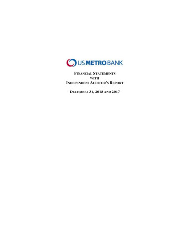
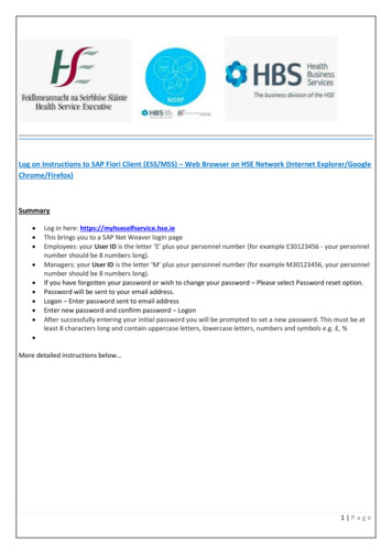
MESA-ESS Specification – December 2018 DraftTermInverterDefinitionDevice that converts DC electricity into AC electricity, equipmentthat converts direct current from the array field to alternatingcurrent, the electric equipment used to convert electrical powerinto a form or forms of electrical power suitable for subsequentuse by the electric system.For battery storage systems, it is typically 4-quadrant and is usuallyconnected to a single battery bank.Referenced ECPThe ECP that a DER’s function references as the source of powersystem measurements. Usually this is either the ESS’s ECP or thePCC, but other ECPs may be referenced.Regional Transmission Operator(RTO)Utility managing the transmission power systemSupervisory Control and DataAcquisition (SCADA)System used by utilities and other facilities for controlling andmonitoring power system equipmentTransmission System Operator(TSO)Utility managing the transmission power system2.Information Management for ESS Configurations2.1Economic Drivers for ESS FunctionsThere are many economic drivers for implementing and interfacing Energy Storage Systems. Based on work bythe “More Than Smart” efforts, more specific discussions in the Sandia “Energy Storage for the Electricity Grid:Benefits and Market Potential Assessment Guide” document 1, and discussion with the MESA members, anassessment of the ESS functions identified in this document is shown in Figure 0815.pdfMESA Standards Alliance14
MESA-ESS Specification – December 2018 DraftUtilities Incentivize ESS to Provide Grid Support ServicesxxxxxxxxxxxxxxxxxxxxxxxxxxxxxxxxxxxMarket: ESS responds to Demand ResponseInstall: ESS under Direct Utility ControlMode: Backup powerxxControl: Provide black start capabilityxxControl: Separate into islanded microgridxxMode: Soft-Start ReconnectionxxMode: Dynamic reactive current supportxxPreset: Voltage Ride-ThroughxxxMode: Frequency-watt (Emergency e.g. spinningxxxxPreset: Frequency Ride-ThroughxxxxControl: Permit reconnectionxxxxxControl: Start / stop ESSxxxxxxMode: Watt-Power Factorx5758xxMode: Fast var supportxxMode: Volt-watt controlxxxMode: Volt-var controlxxxMode: Power factor correctionxxxMode: Fixed power factorxxxUMode: Frequency smoothingxxxZ AA BB CC DD EEFFGGHH II JJ KK LL MM NN OO PP QQ RR SS TT UUTControl: Regulation DownxxxYSControl: Regulation UpxxxV W XQ RControl: Automatic Generation Control (Up &xxxMode: Price and Time-based Charge/DischargexxxContingency and ResiliencyControl: Follow schedule real power and modesxxxG HVoltageFrequencyMode: Real power smoothing of spikes and sagsxxxFMode: Generation FollowingControl: Set Mode Parameters and CurvesxxxEMode: Load FollowingControl: Enable/disable modesxxxDMode: Limit ESS real power to min charge rateMonitor: ESS detailed dataxxCMode: Limit ESS real power to max dischargeMonitor: Metered informationxA BMode: Set real power charge / discharge rateMonitor: Short-term forecast of ESS capabilities53545556Utilities Grid Support Services that ESSMay Provide, as IncentivizedMonitor: Historical informationMonitor: State-of-Charge, status, and measuremenPMarket: ESS bids into Spot MarketOMarket: ESS bids into Day Ahead Bid-Ask MarketL M NMarket: ESS contractual arrangementsKMarket: ESS tariff itemsJInstall: ESS to Respond to MarketIInstall: ESS under Contract, but 3rd Party ControlMonitor: Determine operational characteristicsReal PowerMonitor: Register ESS identitySituational AwarenessMode: Ramp rates for differrent situationsMarketInstallESS Actions and Functions forSupporting the Grid ServicesISO and Transmission Near Real-Time Operations (Day Ahead to Real-Time)Energy Capacity AdequacyProvide real powerLimit energy (load or generation) on constrained transmission pathsMinimize transmission lossesSmooth real power deviationsxFrequency SupportProvide regulation up and/or downProvide synthetic inertia (frequency smoothing)xxxxVoltage SupportMaintain voltage levels on transmission circuitsProvide voltage smoothing on transmission circuitsCoordinate voltage support with distribution automation equipmentSupport power quality requirementsProvide power factor xxxxxxxxxxxxxxxxContingency and Resiliency SupportProvide long term reserves (e.g. non-spinning)Provide fast short term reserves (e.g. spinning and instantaneous)Provide emergency frequency supportProvide emergency voltage supportSupport microgrid islandingDisconnect or cease the export of energy generationProvide black start xxxxxxxxxxxxxxxxxxxxxxxxxxxDistribution Systems Near Real Time Operations (Day Ahead to Real-Time)Energy Capacity AdequacyProvide real power at PCCProvide a schedule of real power at PCCLimit energy (load or generation) on constrained distribution circuitsMinimize distribution losses (e.g. match local generation and loads)Avoid or minimize demand peaksSmooth real power deviationsxxxxxxxxxxxxxxxVoltage SupportMaintaln voltage levels on distribution circuits (e.g. CVR)Provide voltage smoothing on distribution circuitsCoordinate voltage support with distribution automation equipmentSupport power quality requirementsProvide power factor ontingency and Resiliency SupportProvide long term reserves (e.g. non-spinning)Provide fast short term reserves (e.g. spinning and instantaneous)Provide emergency voltage supportMinimize number and length of outagesDisconnect or cease energy generation exportProvide black start gure 1: Economic Drivers: Near-Real-Time Energy Services Mapped to ESS Actions and FunctionsMESA Standards Alliance5
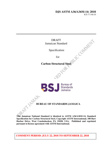
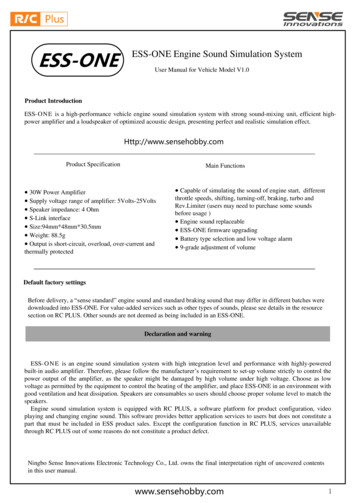
MESA-ESS Specification – December 2018 Draft2.2Overview of DER Hierarchical ConfigurationsDirect control of Distributed Energy Resources (DER) by distribution system operators (DSOs) is neithertechnically feasible nor contractually acceptable for the thousands if not millions of DER systems interconnectedwith the distribution power system. At the same time, utilities are responsible for meeting the reliability andelectrical requirements within their distribution systems and therefore require information on the locations,capabilities, and operational status of these DER systems. In addition, these DER systems can greatly assist inmeeting these utility requirements effectively and efficiently, thus making them proactive stakeholders inmanaging the electric power system.Information exchange is critical to accommodate these complex and dynamic power system requirements, andmanagement of these information exchanges needs to be organized and interoperable. Specifically, a hierarchicalapproach is necessary for the various stakeholders (utilities, aggregators, facilities, markets, and DER systems) toexchange information. At the local level, DER systems generally manage their own generation and storageactivities autonomously based on local conditions, pre-established settings, and DER owner preferences. DERsystems can also be active participants in power system operations and must be coordinated with other DERsystems and distribution equipment. In addition, the DSOs must interact with transmission system operators(TSOs), also known as regional transmission organizations (RTOs) and/or independent system operators (ISOs),for reliability and market purposes. In some regions, retail energy providers, aggregators, or other energy serviceproviders are responsible for managing groups of DER systems either through operational actions or marketactions.This hierarchical approach can be described as hybrid combinations of five (5) levels across multiple domains, asillustrated in the five-level hierarchical DER system architecture shown in Figure 2 and described below. Thecircled numbers identify the various logical information exchanges.MESA Standards Alliance6
MESA-ESS Specification – December 2018 DraftHierarchical DER System Five-Level Architecture, Mapped to the Smart Grid Architecture Model (SGAM)Level 5: Market InteractionsDistribution EnergyMarket ClearinghouseTransmission EnergyMarket ClearinghouseRetail Energy MarketClearinghouseMarket98Level 4: DSO: Distribution UtilityOperational Analysis and Controlfor Grid Management7GeographicInformationSystem (GIS)Level 4: ISO/RTO/TSOBalancing Authority8Utility and REPInformation &Communications(ICT)DistributionManagementSystem (DMS)Level 3: Third Party:Retail EnergyProvider (REP) orDER AggregatorContractualAgreements with DERSystems, Facilities,and AggregatorsOutageManagementSystem (OMS)Demand Response(DR) and/or MarketSystem11Utility WAN/LANAggregator DER &Load m (EMS)TransmissionBus LoadModel (TBLM)6SCADADERCommunicationsSystemDER ManagementSystem (DDEMSor DERMS)4OperationSCADA52System IntegrityProtectionSchemeLevel 2: Facilities DER EnergyManagement System SchemeFacilities DER and LoadEnergy ManagementSystem110Facilities DER EnergyManagement Systems(FDEMS)Level 1: Autonomouscyber-physical DERsystemsEnergy StorageControllerDieselControllerUtility GridArea EPSTransmissionLocal s DER EnergyManagement Systems(FDEMS)PVControllerDieselGeneratorFieldEV as DERController1212PVEquipmentStationFacilities LoadManagementElectric VehicleEquipmentFacilitiesSite LoadsProcessECPMeter atPCCFacilities Site WAN/LAN121213EnterpriseECPECPECPLocal EPSDistributed Energy Resources (DER)Customer PremisesFigure 2: Hierarchical management of information exchanges for DER systems1. Level 1 DER Systems (green in the Figure) is the lowest level and includes the actual cyber-physical DERsystems themselves. These DER systems will be interconnected to local grids at Electrical Connection Points(ECPs) and to the utility grid through the Point of Common Coupling (PCC) (the ECP and the PCC may be thesame if the DER is directly grid-connected). These DER systems will usually be operated autonomously. Inother words, these DER systems will be running based on local conditions, such as photovoltaic systemsoperating when the sun is shining, wind turbines operating when the wind is blowing, electric vehiclescharging when plugged in by the owner, and diesel generators operating when started up by the customer.This autonomous operation can be modified by DER owner preferences, pre-set parameter, and commandsissued by utilities and aggregators.2. Level 2 Facility DER Management (blue in the Figure) is the next higher level in which a facility DERmanagement system (FDEMS) manages the operation of the Level 1 DER systems. This FDEMS may bemanaging one or two DER systems in a residential home, but more likely will be managing multiple DERsystems in commercial and industrial sites, such as university campuses and shopping malls. Utilities may alsouse a FDEMS to handle DER systems located at utility sites such as substations or power plant sites. Forutilities, FDEMS are viewed as field systems and shown at the Station level of the SGAM; however, from afacility’s point of view, they may be seen as enterprises in their own right, and they could then be shown atthe Enterprise and Operations levels.MESA Standards Alliance7
MESA-ESS Specification – December 2018 Draft3. Level 3 Third Parties: Retail Energy Provider or Aggregators (red in the Figure) shows market-basedaggregators and retail energy providers (REP) who request or even command DER systems (either throughthe facility’s FDEMS or via aggregator-provided direct communication links) to take specific actions, such asturning on or off, setting or limiting output, providing ancillary services (e.g., volt-VAr control), and other gridmanagement functions. Aggregator DER commands would likely be price-based either to minimize customercosts or to respond to utility requirements for safety and reliability purposes. The combination of thirdparties (this level) and facilities (level 2) may have varying configurations, responsibilities, and operationalscenarios but, overall, still fundamentally provide the same services.4. Level 4 Utility Operational Grid Management (yellow in the Figure) applies to utility applications that areneeded to determine what requests or commands should be issued to which DER systems. DistributionSystem Operators (DSOs) must monitor the distribution power system and assess if efficiency or reliability ofthe power system can be improved by having DER systems modify their operation. This utility assessmentinvolves many utility control center systems, orchestrated by the Distribution Management System (DMS)and including the DER database and management systems (DERMS), Geographical Information Systems (GIS),Transmission Bus Load Model (TBLM), Outage Management Systems (OMS), and Demand Response (DR)systems. Transmission System Operators (TSOs), regio
When IEEE 1547:2018 was released in April 2018, the IEC 61850-7-420 was also submitted to the IEC as a Committee Draft (this is the normal process for creating a standard). At the same tim